TV-3C/U Tube Tester
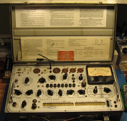
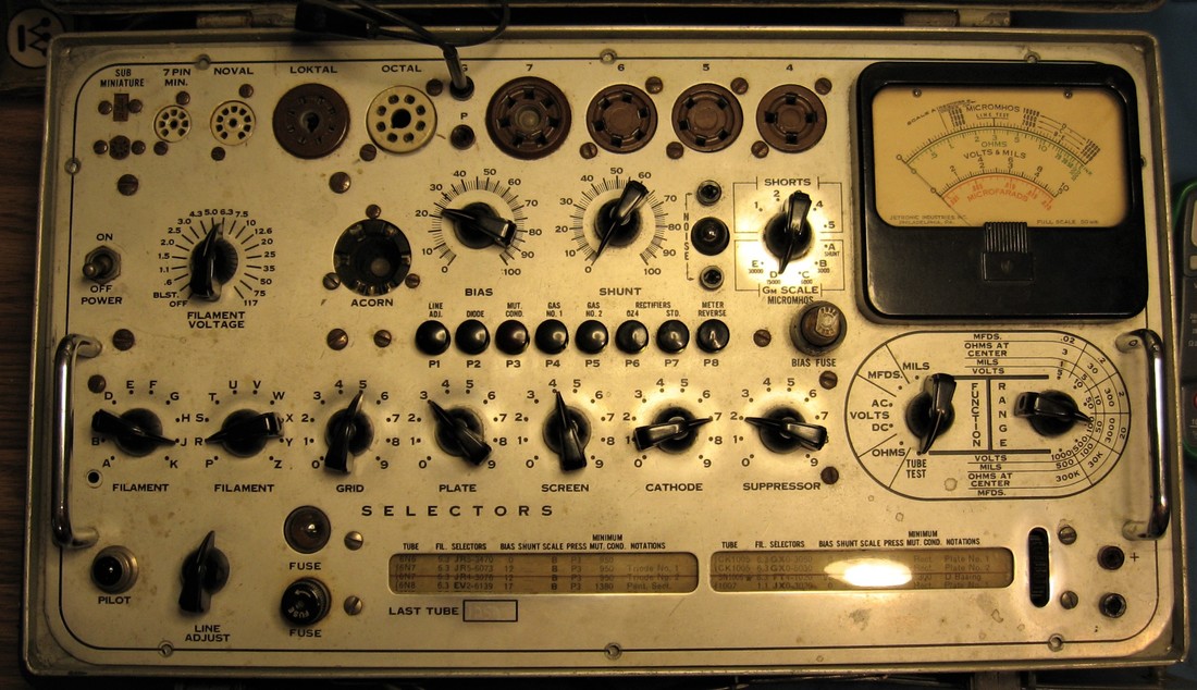
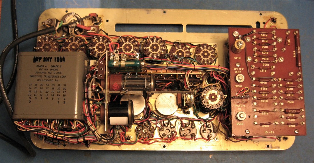
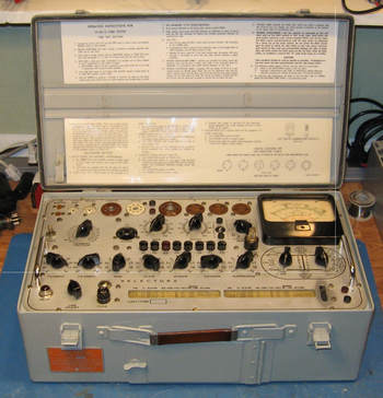
This military TV-3C/U tube tester has a May 1954 date stamped on the power transformer and was manufactured for the Navy by Jetronic Industries. It's a Hickok design and the TV-3 conveniently reads micromhos directly on the meter scales. It was superseded by the TV-10 in the early '60s. The TV-10 and TV-3 are similar but the TV-10 doesn't have the VOM functions, and was updated with more tube sockets.
|
I had been looking for a high quality tube tester but did not want to pay the kind of prices a TV-7 or Hickok 539 command, so when I ran across this very capable tester for substantially less I snapped it up. It has comparable functionality to the higher-priced sets and will provide all the capabilities I'll personally ever need in a tube tester.
This set was advertised as being in "very good working condition", but when I received it and made some initial checks I quickly discovered there was no plate voltage from the #83 rectifier. So much for working condition. Fortunately the issue was just corroded pins on the 83 tube and after a quick cleanup I had plate voltage. Later, I discovered there was no bias voltage either, so not much of a chance this thing was working when sold. Another issue was glaringly obvious as soon as I opened the box and got an up close look at the tester - it's mounted in the wrong case. It's so blatantly obvious only a fleabay seller could miss seeing it. |
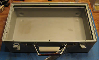
The lid won't close completely down over the front panel because it hits the front panel handles. And only a couple of front panel mounting screws can be matched up to threaded holes in the cabinet. I think this case is actually made for either an "A" or "B" model.
The front panel of the earlier variants must be ever so slightly different from the "C" because there's just no way to get all the screw holes in the "C" front panel to line up to the case holes. Plus there's an additional annoyance with the power transformer bumping up against an internal rib on the left inside of the case which doesn't allow the front panel to center up perfectly in the cabinet.
The front panel of the earlier variants must be ever so slightly different from the "C" because there's just no way to get all the screw holes in the "C" front panel to line up to the case holes. Plus there's an additional annoyance with the power transformer bumping up against an internal rib on the left inside of the case which doesn't allow the front panel to center up perfectly in the cabinet.
|
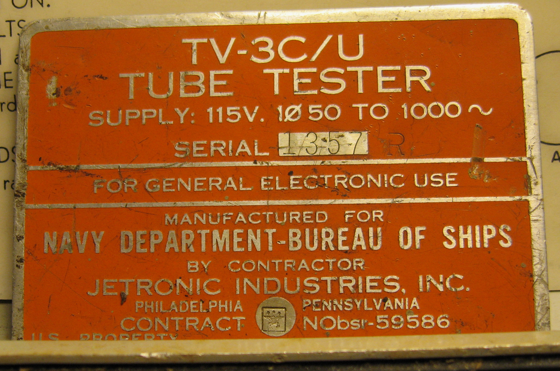
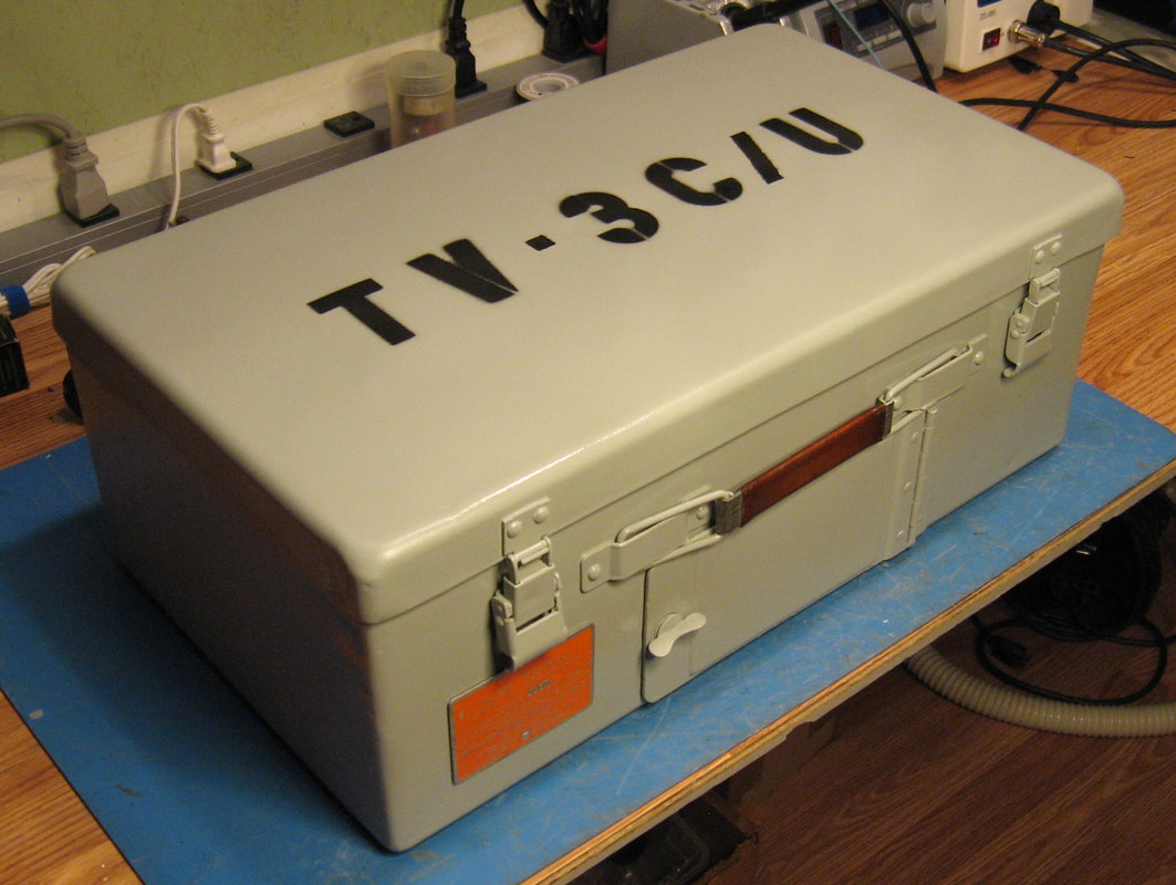
The outside of the case had been stripped down to bare metal so it wasn't much to look at, and the nomenclature plate was missing, but while digging through the storage compartment I was happy to find someone had tucked the plate in there. That will go back on the case's front corner once it's painted.
|
To make the case fit properly I had to cut a notch out of the left side internal rib where the power transformer was hitting, so the front panels centers up.
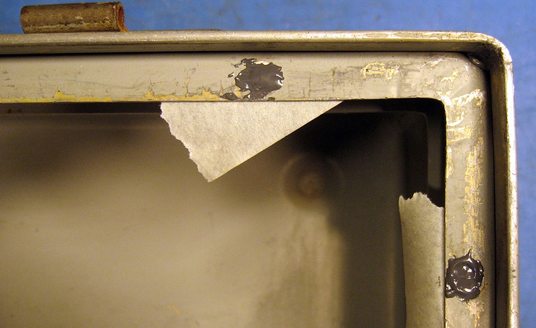
All the crimp nuts in the top flange of the case, for the front panel mounting screws, were removed and the holes filled. Then I drilled new holes to match the "C" front panel hole pattern and crimped in new 6-32 nuts.
I removed the two handles from the front panel, and using a wood block to keep the handles perpendicular, I sanded off about an 1/8" from the handle bottoms. They're chromed brass so not too hard to sand down. This was enough to allow the lid to close properly.
Next the cabinet exterior was repainted, but since the interior had not been stripped it was left it in original condition.
In the photos it's easy to see how the mounting holes will not line up. The second photo is after removing the crimp nuts and filling the holes. They still need sanded so new holes can be marked and drilled for the new nuts.
The roll chart is not dated and has part number A-594-1153 and says TV-3C/U on it. It's still in good condition, although someone has penciled in some tube settings in the spaces at the bottom provided for that purpose.
|
There are two fuses holders on the front panel of the TV-3C. One is for the Line and the other is for the Bias supply. Fuses are added to equipment to protect it, a fact that seems to be lost on some people. The AC line fuse in this tester is supposed to be 1.5A but someone installed a 5A fuse, over 3X too high. Likewise, the Bias fuse is supposed to be 125ma but there was a 2A fuse installed. That's 16X too high - the transformer winding would probably open before blowing a 2A fuse, which kinda defeats the whole purpose of having a fuse.
|
|
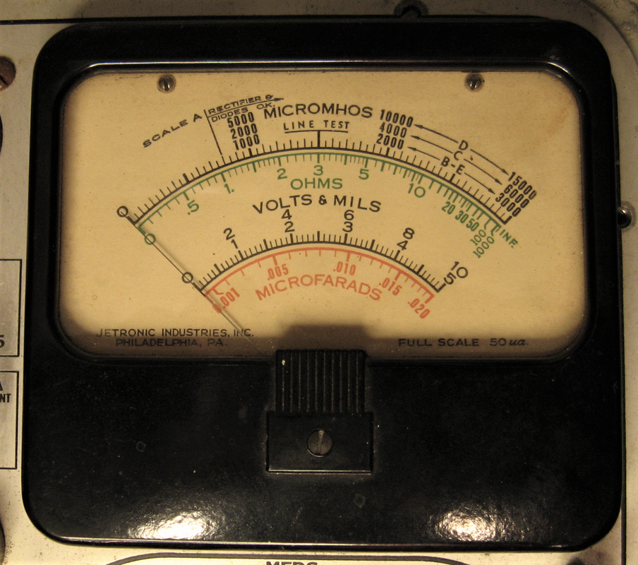
The meter is in good shape and doesn't exhibit any nasty issues such as sticking. The VOM functions take up more real estate on the dial than the tube micromhos scales.
This is a 1000 ohm/volt VOM so it might be useful when calibrating other tube testers, but otherwise I'm not likely to reach for a tube tester when all I want is a VOM. |
|
Most of the front panel screw heads are corroded and need cleaned and polished. Some are a pain to get to the nuts to take them out.
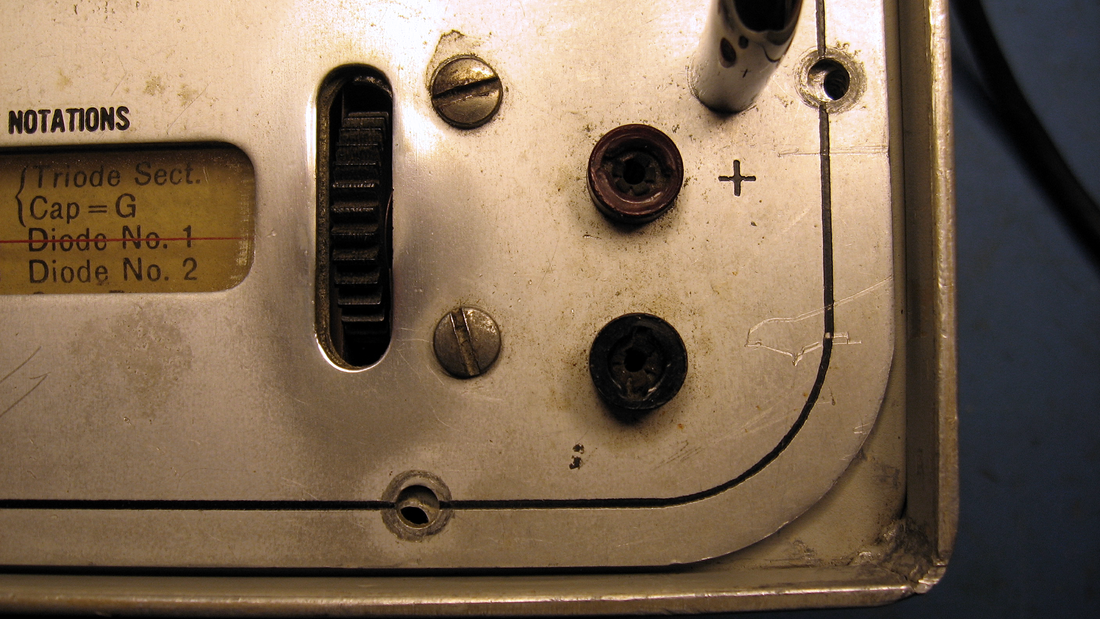
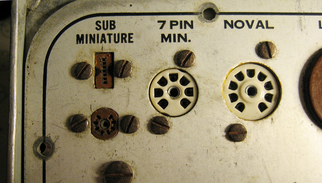
The front panel appears to have some kind of clear coating on it which is pretty good at holding onto dirt. The tube socket contacts also need cleaned with Deoxit. And once again, it's easy to see how the panel screw holes don't line up. |
|
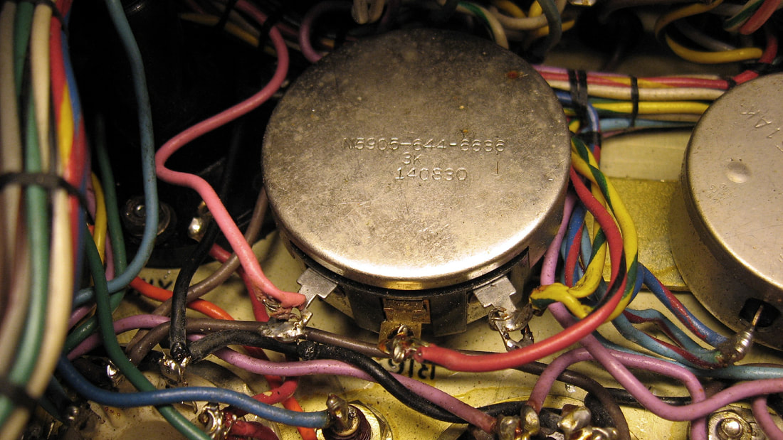
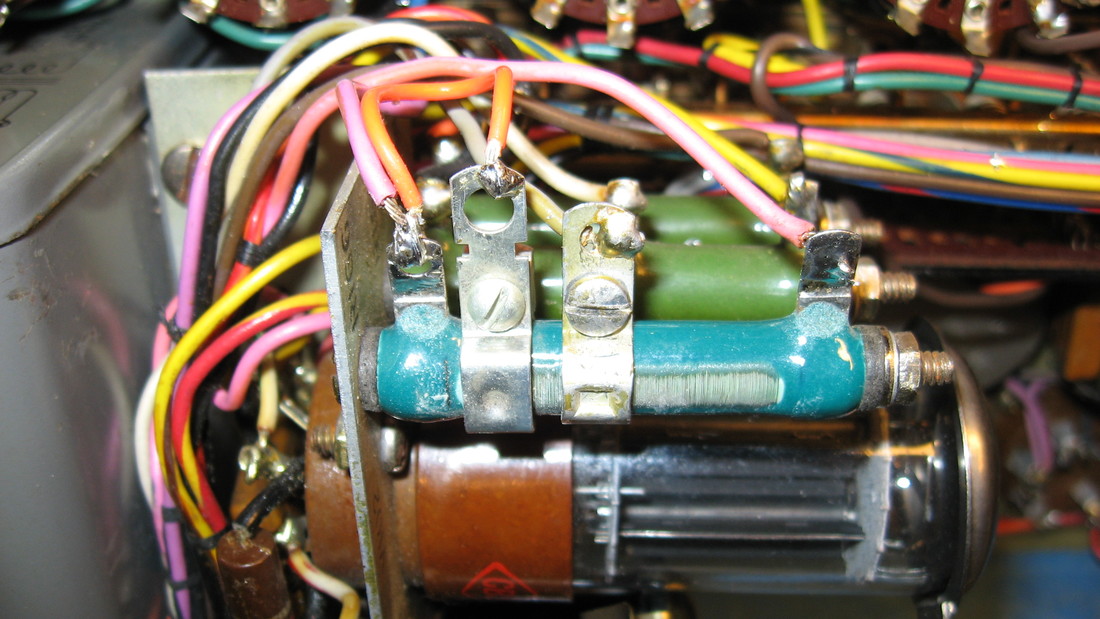
From the melted insulation and poor soldering on the Bias pot it is obvious someone has been inside. I unsoldered and checked the pot, trimmed up the melted insulation on the wires that were long enough to do so, added some insulated sleeves to the too-short yellow-striped wires which had been stripped backed too far, and then resoldered all the connections.
I was curious why someone was checking the pot and as I began testing I discovered the reason. Although I thought I measured the -40VDC bias during the initial checks, when I started to calibrate the unit I didn't have any bias voltage. That's when I discovered that resistor R166, which is in series with this pot, was open. |
|
I couldn't find any damage to R166 but it is open in the middle of the resistor winding in two places. Interestingly, this dead area in the winding is exactly the width of the contact on the slider. Also the resistor is supposed to have two sliders, and one is missing, so it's obvious someone was in here before me. I ordered a replacement power resistor online.
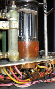
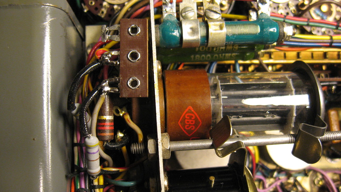
Also in the photo is the 5Y3 tube and below it a 1200 ohm resistor which is carbon composition. This resistor is one of the few composition resistors still in spec so I didn't bother to replace it. It's easy enough to get to if it ever does need changed. The 5Y3 is original and was tested to ensure it still has balanced sections. |
|
The R166 replacement showed up in just a few days from Surplus Sales of Nebraska. It is an 8K ohm adjustable resistor vice the 8.5K ohm original. It only came with one tap so I used the slider from the original resistor as the second tap.
After installing R166 I found that setting the Line for a plate supply of 150VDC caused the 130VDC Screen supply to be at least 3V high using a #83 rectifier and 7V high with a solid state tube. This also made the Bias voltage and Low Screen voltage a little too high. |
|
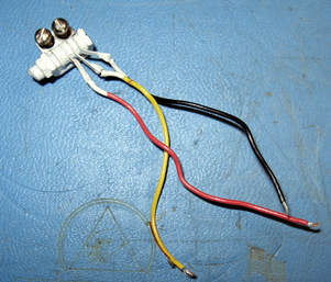
The best way I found to get all the voltages in spec all at the same time was to add 470 ohm resistors in series with the 5Y3 plates. A small terminal strip was installed next to the tube socket for the resistors. The value was determined by substituting resistors in the circuit until I got the correct voltages.
|
|
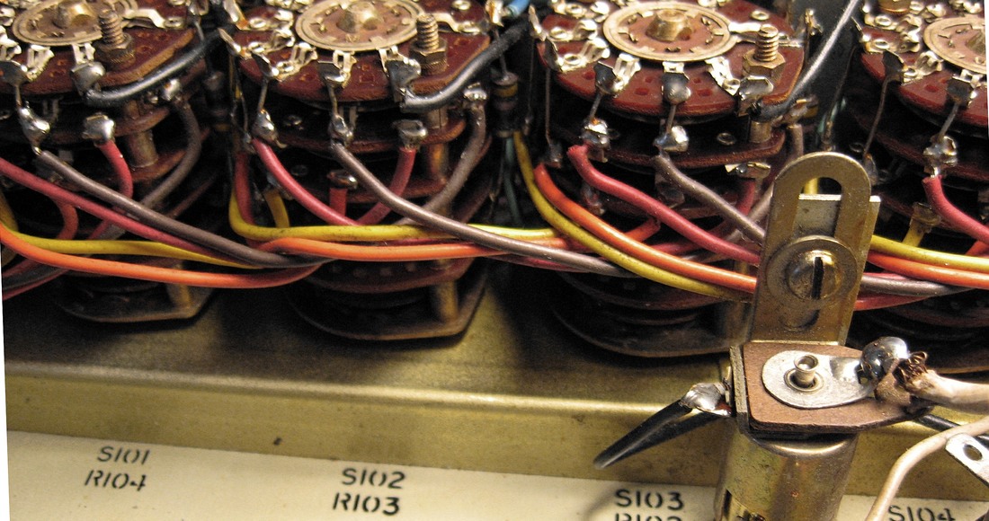
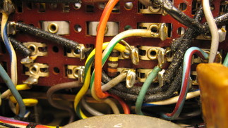
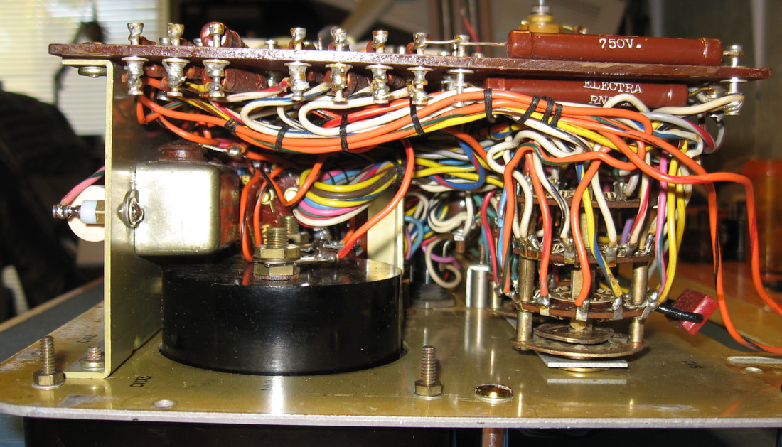
There are several other carbon composition resistors in the tester and most of these needed replaced because they've drifted high from age. R102, R103 and R104 are 47-ohm resistors buried in between the selector switches and are a bit of a pain to replace. Only two measured high but I replaced all three while I was in there. They're on S101, S102 and S103.
I also replaced R116 (330K) carbon comp resistor on the neon lamp, and R101 (1Meg) resistor on S107. |
|
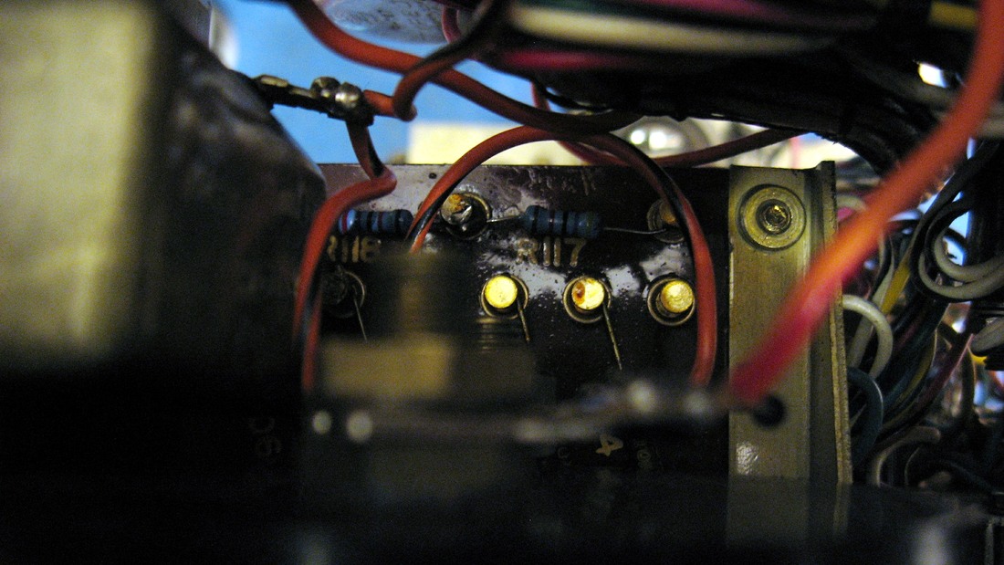
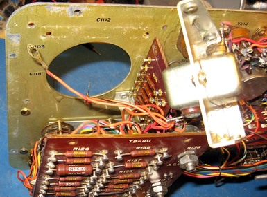
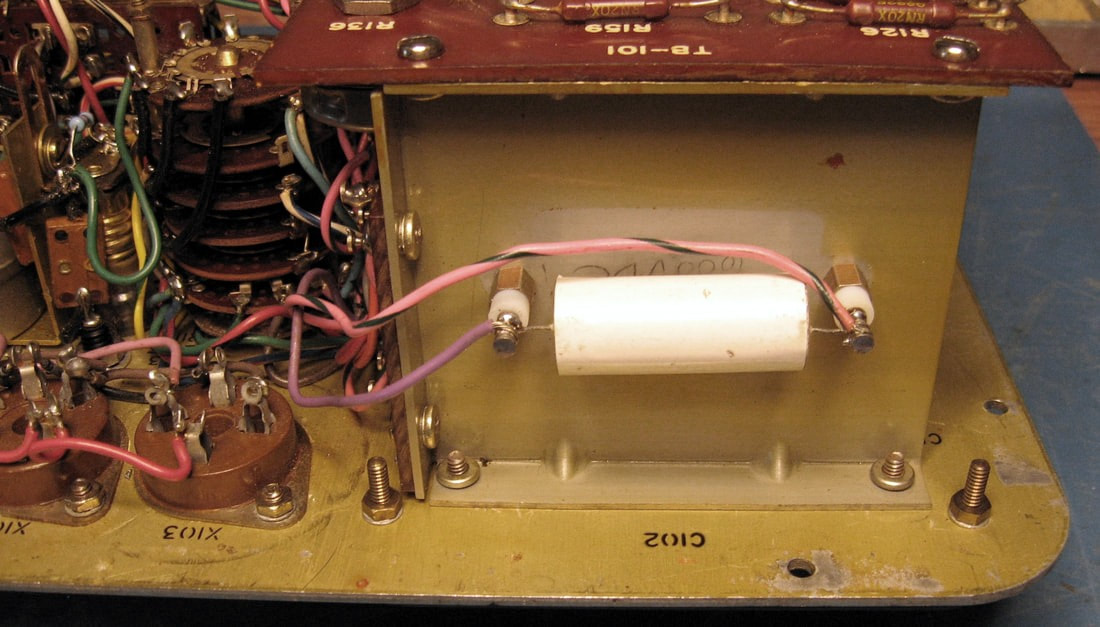
I had to remove the meter to get at some screws that need to be removed to get into the area where R117 and R118 are, and also to get at the nuts on the screws for the two bathtub capacitors. Military stuff is well built, but they can really stuff a lot into a small space at times.
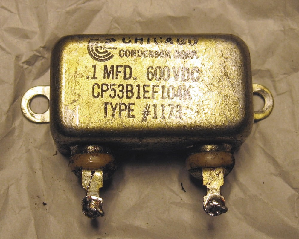
The bathtub for the 100uF capacitor is on the inside of the aluminum mounting plate and the 0.1uF capacitor for the shorts test circuit is mounted on the outside. |
|
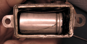
The bathtub for the 0.1uF capacitor is an oil-filled capacitor and is leaking around the seals for the terminals. Some of these old oil-filled bathtub capacitors contain PCBs and, since there's no way to know, I assume every oil-filled cap has PCBs and I don't mess around with them. I canned it and carefully cleaned up all traces of the oil.
|
|
The line meter circuit wasn't reading correctly and I thought it might be the copper-oxide rectifier, so I pulled it. Turns out it might have still been serviceable. The forward readings were high at around 800 ohms, higher than the 500 ohms max stated in the manual, but the reverse readings were good at about 40K ohms on both diodes. It's obviously aged, but it is 63 years old.
The real issue was that I accidentally used the wrong line test diagram, for a TV-10 which is a little different from the TV-3C, and didn't realize I needed to calibrate the AC Voltmeter. The TV-3C actually uses the 100-volt AC meter range to check the line voltage setting and these rectifiers are part of the AC voltmeter circuit. |
|
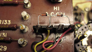
I replaced the copper rectifiers with two 1N34A Germanium diodes mounted on a miniature terminal strip. It was easier to mount the terminal strip on the top side of TB101 and run the connecting wires through one of the mounting holes for the original rectifier.
After replacing the diodes I followed the manual's instructions and calibrated the AC voltmeter. |
|
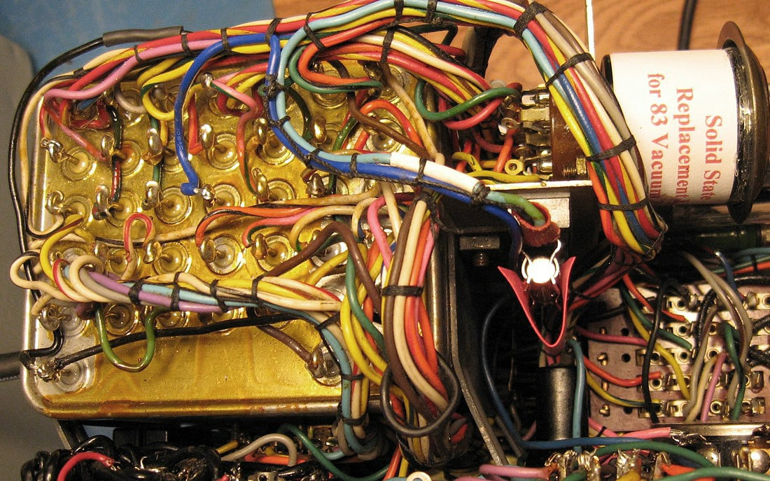
One last thing I almost forgot to do is add a fuse to the #83 tube high-voltage out line because I'm using a solid state replacement tube. This protects against the possibility of a diode shorting. It's not likely but just in case. I removed the blue wire from transformer pin 20 and ran it to a fuse holder. Then another blue wire was run from the opposite end of the fuse holder back to pin 20. I placed the fuse holder on the underside of the bracket that holds the tube sockets.
The high-voltage winding is rated at 3A but I installed a 2A fuse to be on the safe side. That's worked out fine so far. |
|
I built a test fixture called an Alternating Current Sink to check transconductance accuracy. The ACS should ideally give a reading of 1000 uMhos on the B, D and E ranges and 500 uMhos on the C range. This TV-3 reads approximately 1000 - 1010 on the B, D and E ranges and it was spot on at 500 umhos on the C range.
The ACS is detailed on the Alternating Current Sink page. |
|
Finally, all back together again. The new paint job matches pretty well with the original paint on the inside. About as close a match as I was going to find off-the-shelf at the hardware store.
The manual shows the nomenclature tag mounted on the left front and I attached it with automotive grade double-sided tape. |
Last update 10/18/2017

