Restoring a Supreme Model 561 Combination AF and RF Metered Generator
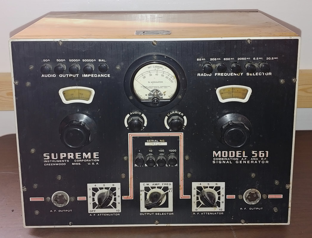
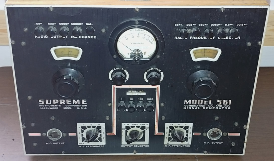
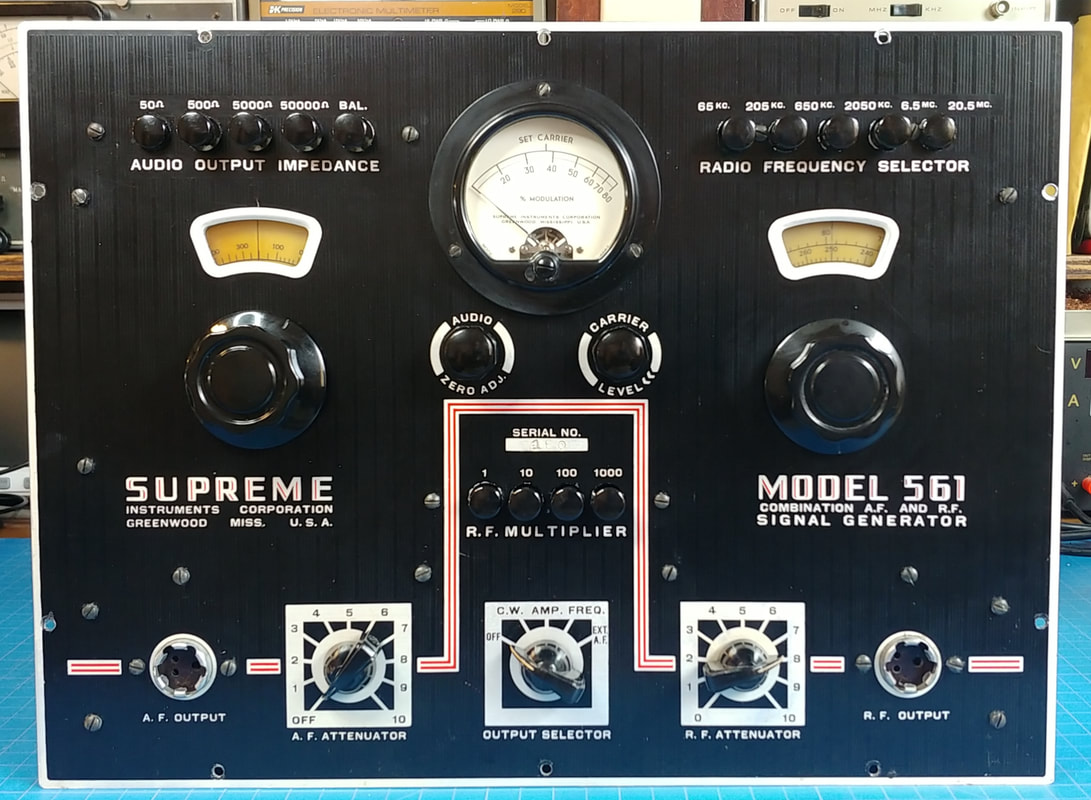
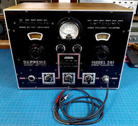
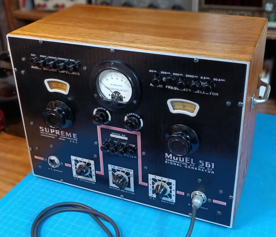
The model 561 is an AF generator, RF generator, and frequency modulator, and according to Supreme, can provide any type of signal needed to test or align a radio receiver of the day. The generators can be used individually or in conjunction with each other. The 561 also has two vacuum tube voltmeters, one for setting percent of modulation, and the other for setting the carrier level of the unmodulated RF signal.
The audio generator's range covers 15 to 15000 CPS, and the RF generator's fundamental range is 65KC to 20.5MC, with an extended range to over 60MC using 2nd and 3rd harmonics (the updated model 666 claimed up to 120MC). And the RF output can be either amplitude or frequency modulated.
Supreme's explanation for using harmonics on high frequency RF ranges was that using harmonics of the more easily calibrated lower frequency fundamental scales was more accurate than adding high frequency fundamental ranges that are harder to keep calibrated.
Supreme's explanation for using harmonics on high frequency RF ranges was that using harmonics of the more easily calibrated lower frequency fundamental scales was more accurate than adding high frequency fundamental ranges that are harder to keep calibrated.
|
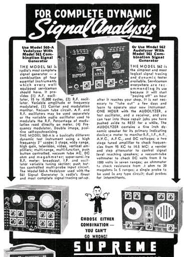
The 561 was advertised in combination with a Vedolyzer or an Audolyzer as a complete dynamic signal analysis system. Now that I've found the generator I have all three instruments. There is also a booklet called "See The Signal" that details use of the 561 with the Vedolyzer.
The 561 first shows up in ads in 1939 and in Supreme's catalog for 1940. It is pictured with a leather handle on top of the cabinet and it's missing the Carrier Level control that later units have.
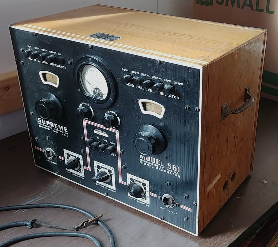
The Supreme 1941 catalog shows the model 561 with an updated front panel that includes the Carrier Level control, and it now has metal handles on the sides. They also added $10 to the price tag. |
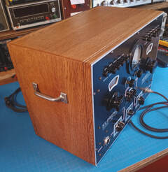
The 1940 Supreme catalog also states that the 561 was sold in an oak cabinet. 1946 was the last year it was advertised in oak and with the original black faceplate. In 1947 it had a new wrinkled gray color scheme in a steel cabinet with matching front panel.
The 561 was sold through 1947 and was replaced by a new model 666 in 1948, which is really the same generator in another new color scheme, and with the outdated 84 and 6F8 5-pin tubes replaced with 6SN7 and 6X5 octals.
The 561 was sold through 1947 and was replaced by a new model 666 in 1948, which is really the same generator in another new color scheme, and with the outdated 84 and 6F8 5-pin tubes replaced with 6SN7 and 6X5 octals.
|
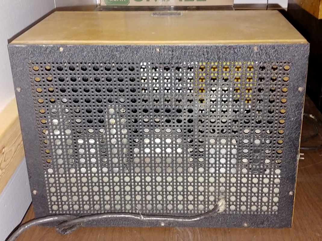
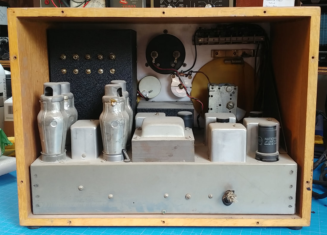
This 561 is an early serial number (160) and looks to be in original condition. Someone has taken good care of it and it even came with the original manual with matching serial number, and an original output cable.
I was also surprised to find several typed pages of alignment instructions that are the ones you could only get by writing to Supreme and requesting them. Alignment instructions for Supreme equipment seem to be as rare as hen's teeth and these are the first I've found for any of my instruments. I created a PDF of them and sent it to the Supreme Instruments website so they'll be available to anyone who needs them. |
These alignment instructions should prove just as useful with the model 666 AF/RF generator, and the AF section should work for the models 563 and 680 audio generators. And I'm guessing the RF frequency alignment points and general procedure should also work with Supreme's smaller generators, the 571, 576, and 661, which have exactly the same bands and frequency coverage.
|
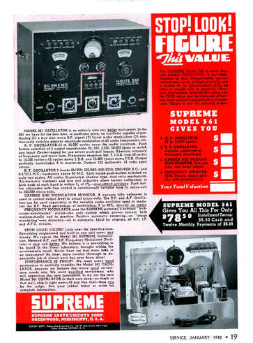
The alignment instructions also state that in serial numbers below 150 the Band "A" trimmer is located under the chassis, and in units produced afterwards it is on top of the chassis beside the 6K6, which may be an indication of exactly when the 561 was updated. In a Supreme ad in the January 1940 "Service" magazine the model 561 pictured already has the new front panel layout with the Carrier Level, so the original version was apparently replaced very early on.
If S/N 150 is when Supreme updated the generator then they did not reset serial numbers for the change and this S/N 160 generator would be the 10th or 11th newly updated instrument (the Supreme notes are unclear as to which side of the fence S/N 150 falls on). It also indicates this instrument dates to 1940. |
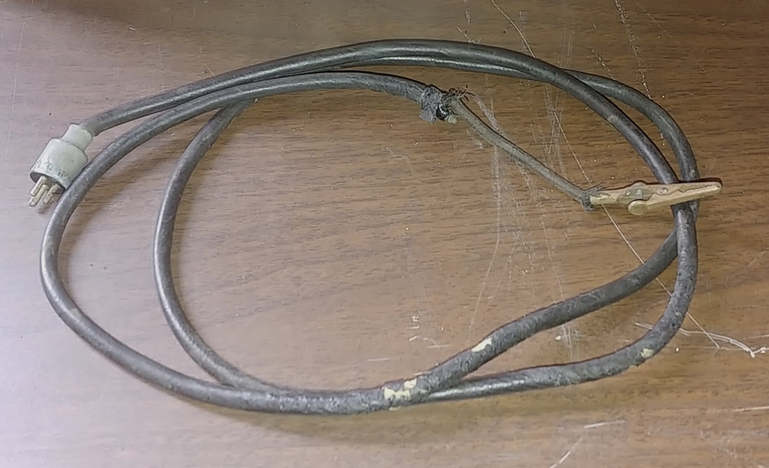
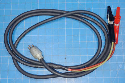
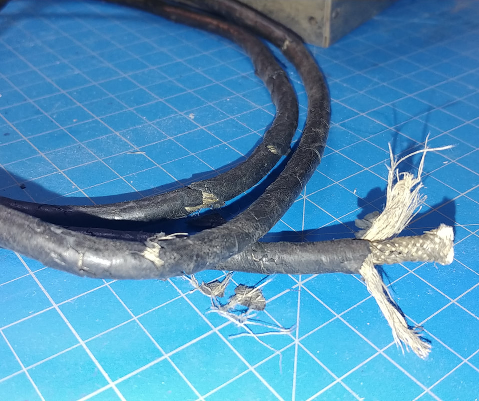
The original output cable is dry rotted but it provided all the details, and the 3-pin plug, for creating a new one. I also have a second 3-pin plug somewhere (it's gotten misplaced in the move) to make a second cable since the instrument originally came with two. Both the original and the new are made from shielded microphone cable.
|
The front panel pushbuttons need a little help. Some are sticking and others protrude a little too far from the faceplate. In both cases the issue is probably old deteriorated rubber bumpers and needing a good cleaning. Otherwise everything looks good on the front and it just needs cleaned up and polished.
|
|
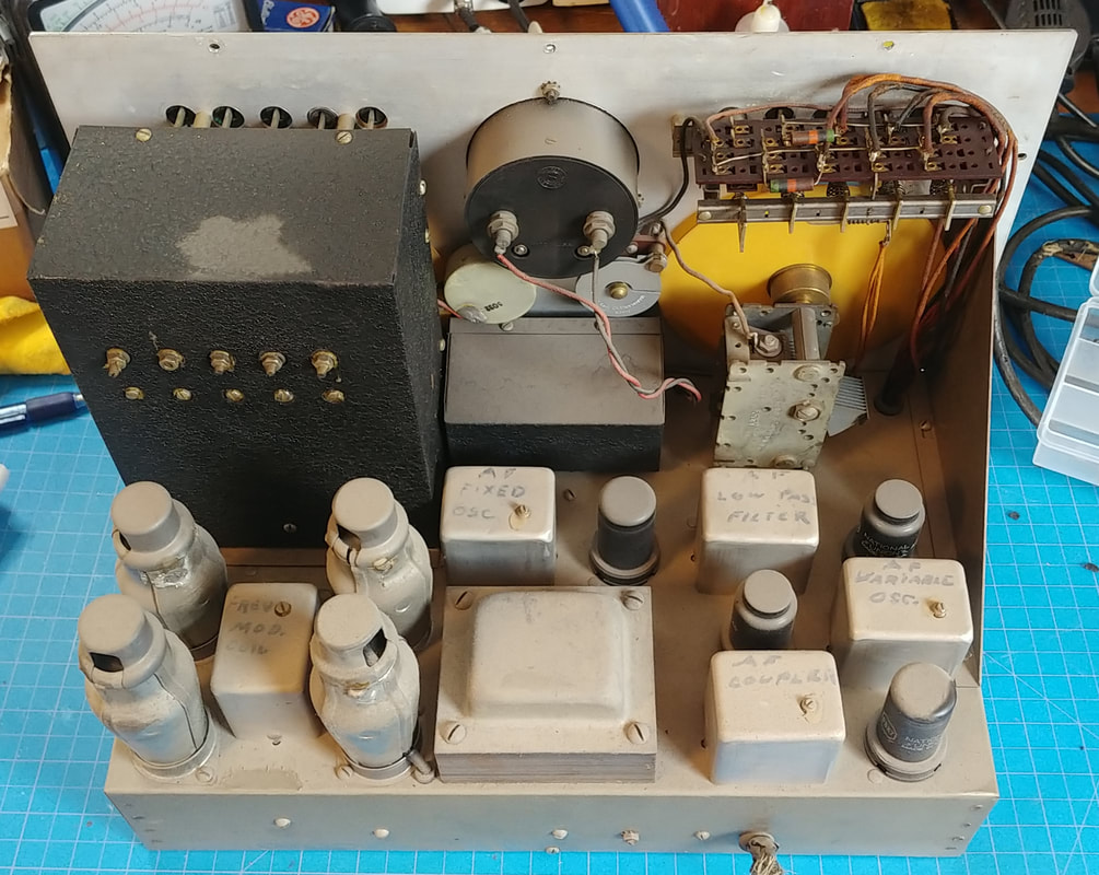
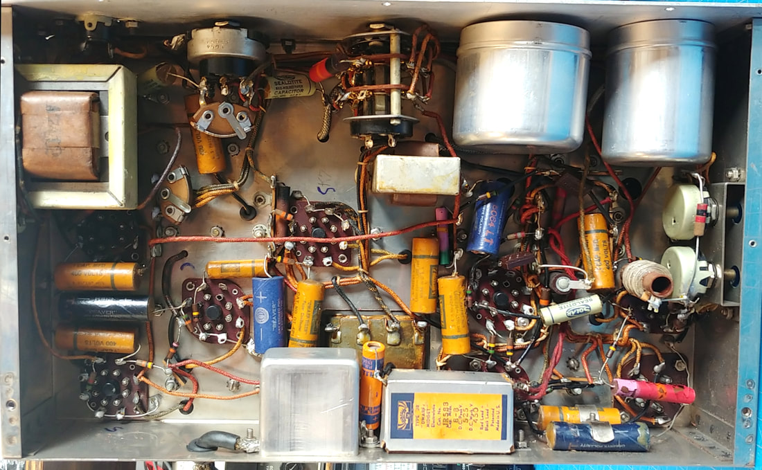
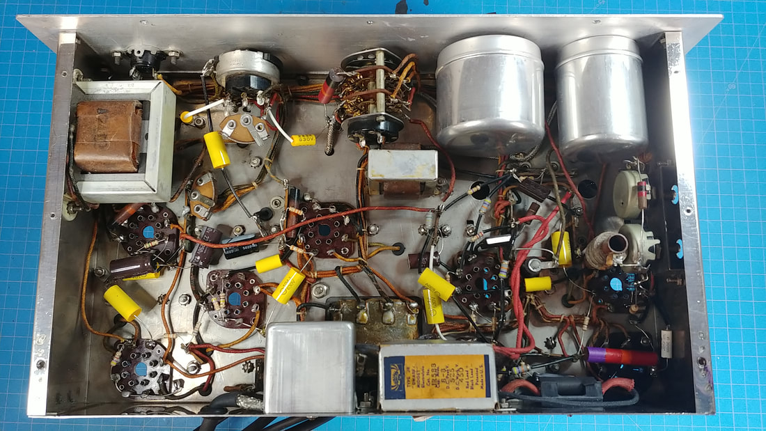
Under the chassis is clean. It has been worked on in the past: the power supply filter capacitors in the silver box were replaced as well as one other electrolytic.
This generator must have been stored in a climate controlled area, since there's no rust to speak of, and many of the old style resistors are still close to 20% tolerance. |
|
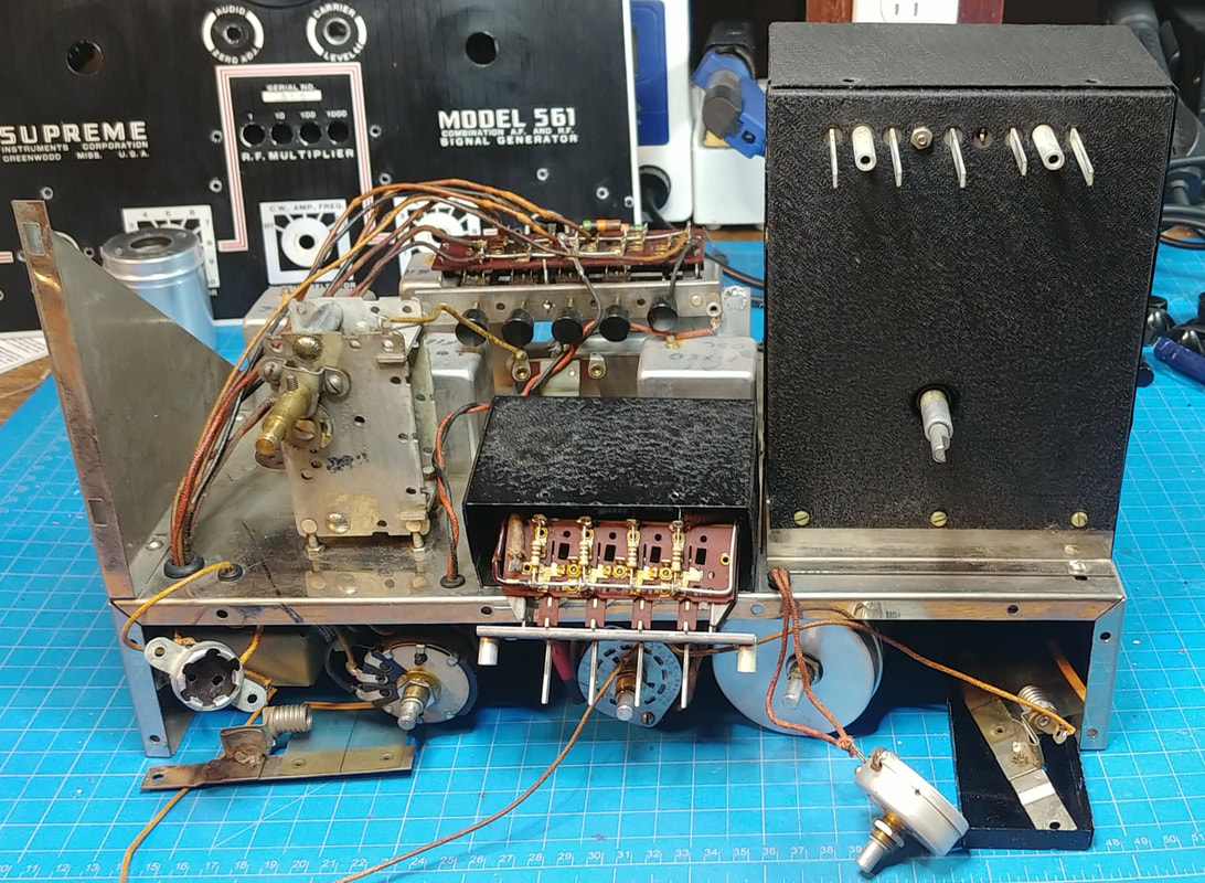
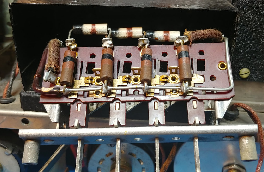
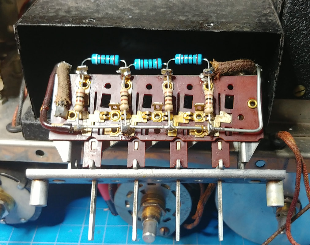
Inside the RF Multiplier. This was a bear to get at with having to remove the front panel of the generator, the screws that secure the front of the multiplier box, and unsoldering the two shielded cables from ground lugs under the chassis. This frees up the cables to feed them through chassis holes and into the multiplier box so the switch assembly can be extracted out the front. I also removed the faceplate off the assembly to make access to the multiplier resistors as easy as possible.
|
|
Because of the difficulty getting to the RF Multiplier resistors, all of them were replaced. And I used 1-watt resistors instead of the original 1/2-watt. There are three 900Ω and four 100Ω resistors and none of them have a tolerance band. If they were meant to be 20% tolerance then a few were still OK, but I have seen in other Supreme gear where precision resistors had no tolerance band and were hand-picked for accuracy. Since I have no idea what tolerance Supreme intended, I hand-picked replacements to 1% tolerance and hopefully I won't ever have to open the multiplier box to replace attenuator resistors again.
|
A few weeks after finishing the multiplier assembly I picked up a Supreme model 576 generator which has the same multiplier attenuator circuit as the 561 (but uses a different switch assembly). All the attenuator resistors in it are 5% tolerance, so I think that answers the question of what tolerance the 561 resistors were.
A note of caution about the attenuator resistors. There is no DC blocking capacitor on the generator output to protect these resistors from overheating if the output is connected to a DC voltage point while in use. So an external capacitor must always be used. This is the same issue I found in the Hickok 288X, where the resistors had been overheated by someone who did not use a blocking capacitor.
Interestingly, a couple of Supreme's smaller generators, the model 576 and 661, had such a capacitor installed in the output line, and one of their advertised features was that the RF output was protected from DC voltage burnout.
And when servicing transformerless AC-DC radios the manual recommends a 0.5uF capacitor in series with both the center conductor and the shield of the output cable, with a 100KΩ resistor tied between the capacitors as shown in the manual's Figure 10.
These same cautions also apply to the audio output transformer. It should be protected from burnout by using blocking capacitors if connecting it into a live circuit.
|
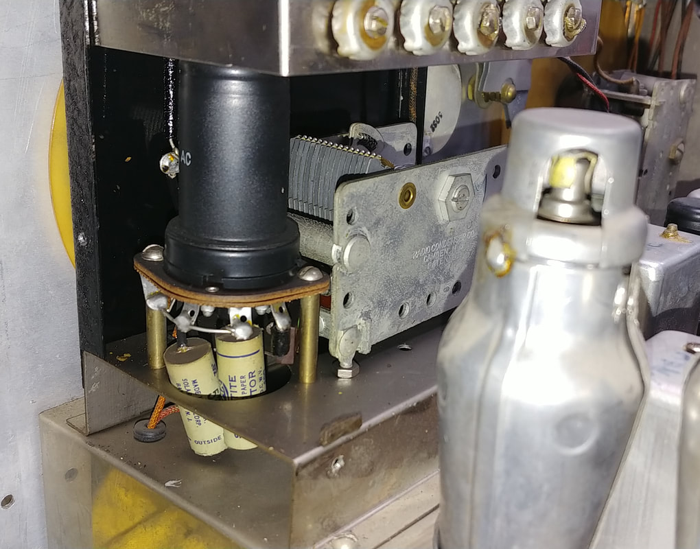
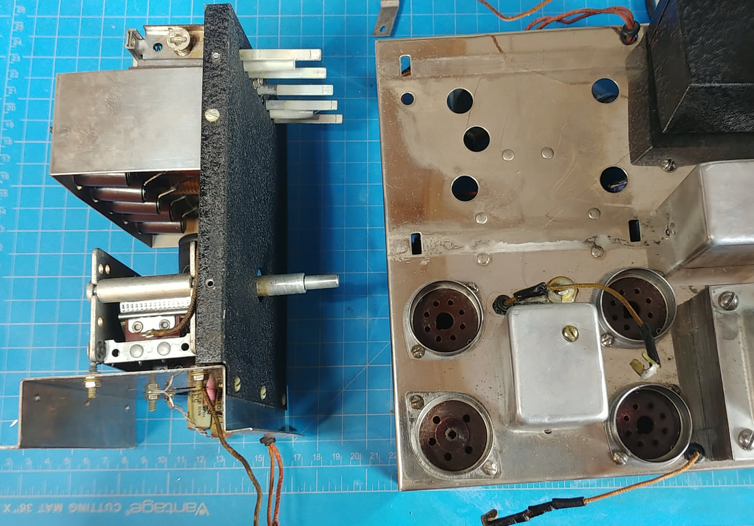
I had to completely remove the RF generator box from the chassis to replace the two paper and foil capacitors, and a couple of hard to get to resistors, and to clean and polish the chassis chrome underneath.
Right above the aluminum shield can in the photo, and just to the left of the 6K6 socket, is Band "A" trimmer C-49. I am also replacing any cracked or broken grommets as I go. Most are hard as rocks. |
|
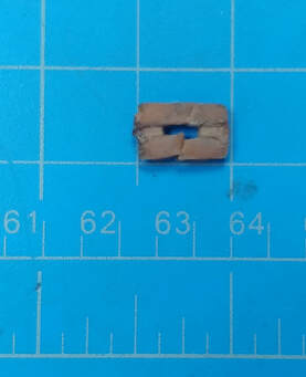
This is one of the rubber bumpers from the pushbutton switches. Each pushbutton has one glued to the switch bracket and it looks like they were slipped on the shafts as the switches were assembled because I had to cut it off. I only found two that were not melted goo. These rubber bumpers are actually a necessary part for the proper action of the switches, so I have to make new ones. Instead of trying to recreate each bumper separately, I cut a rubber strip for each set of buttons with cutouts for each individual shaft and slits cut to slide the rubber around the shafts. Then the rubber strip was glued to the front bracket.
|
|
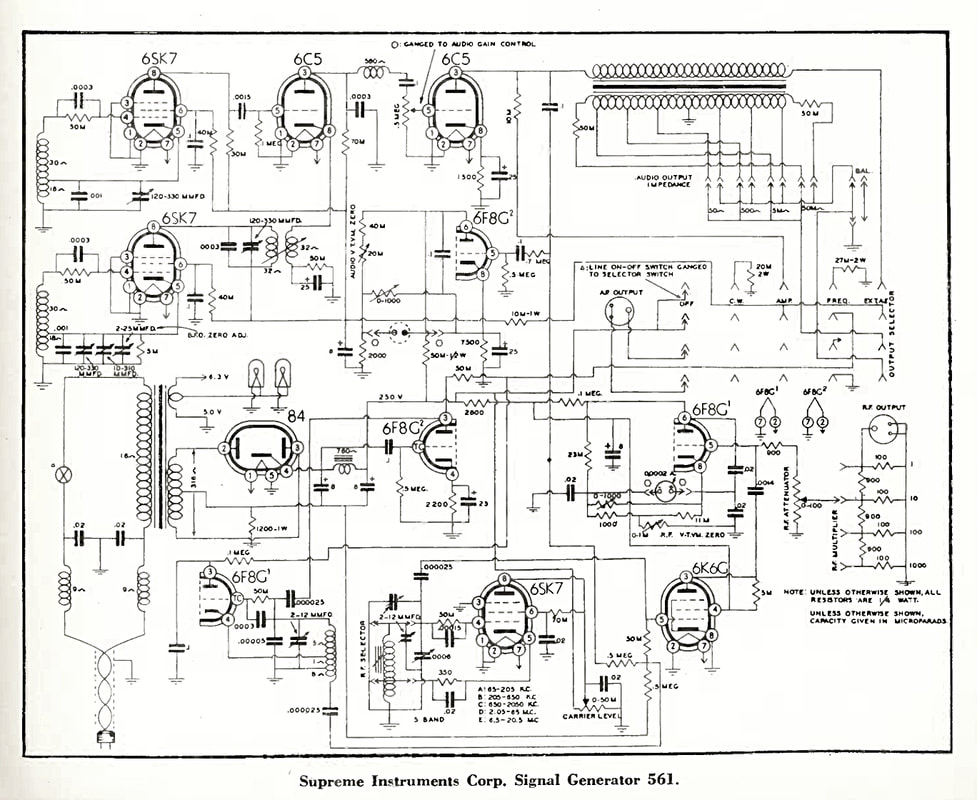
While working on the 561, I noticed part of the circuit around the Carrier Level control didn't match the schematic I was using, which came from the Supreme Instruments website. This schematic is dated 10-5-1944.
In this image is another schematic from the December 1944 Radio Service Dealer magazine, which does match my generator's circuit. I hadn't realized before that the two schematics are not identical, and there are other differences besides the carrier level, but the RSD version of the schematic is correct for this s/n generator. |
I also checked the schematic for the updated model 666 generator from 1948, and oddly enough the Carrier Level circuit in the 666 matches how it's wired in my early 561. Since the 666 is basically the same generator, with just the two updated tubes, its schematic is very close to the 561, and useful for comparison.
What I don't quite get is why the carrier level circuit in my early generator was changed by the time of the 1944 Supreme schematic, and yet still matches the updated 1948 generator's circuit.
What I don't quite get is why the carrier level circuit in my early generator was changed by the time of the 1944 Supreme schematic, and yet still matches the updated 1948 generator's circuit.
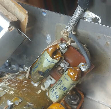
I pulled the aluminum can off the AC line filter and found the two original paper and foil capacitors, one on each side of the AC line to chassis ground, have literally melted. One is a dead short to the chassis, and the other has less than 15KΩ cold resistance to the chassis. Plugging this set in without any protection would not have ended well.
Up to this point I hadn't found any issue that would prevent the generator from powering up and working, but this problem would have stopped it dead in its tracks. And maybe the operator, too.
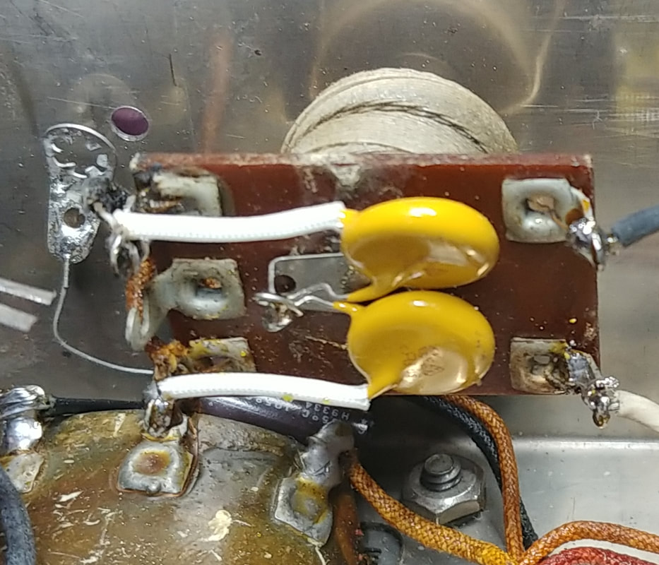
This is a really good example why it's not a good idea to just plug in a new aquisition before checking inside for exactly this sort of hazard. It's also explains why I use an isolation transformer, a variac, and a dim bulb tester to protect myself and the equipment I'm working on. And it shows why non-safety rated capacitors on the AC line should be replaced with proper safety caps. These replacements are 0.01uF X1Y2 capacitors.
|
Under the chassis is completed and ready for a test. All the electrolytic and paper capacitors have been replaced. The original mica caps tested OK and were left in place. Most of the resistors have been replaced. For the sake of originality I left a few that are easy to access, are still within 10% tolerance, and are stable when heated. These are the higher wattage resistors.
Some of the old style resistors, mostly the 1/4-watt ones in this set, actually go low from age, and are so unstable that when they heat up, such as when desoldering another part, it causes their resistance to drop dramatically. So they had to go too, because I don't trust them. |
An AC line fuse was also added. The fuse holder is mounted on the right side in the photo, in place of the clamp that previously held down two of the old capacitors. By using the screw hole for the clamp I didn't need to drill a hole in the chassis to mount the fuse holder. Drilling holes in a beautiful chromed chassis is just not an option.
|
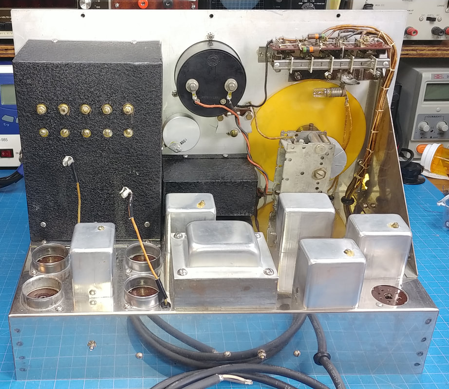
The top of the chassis is ready for testing, too. The chrome has been cleaned and polished and looks pretty good for its age. The aluminum cans were all opened and checked. There are mica capacitors inside all of them, and a couple cans also have 50KΩ resistors inside. The resistors are in grid circuits and are still within 10%, so I didn't disturb the delicate coils they are attached to. I also didn't disturb the micas for the same reason and will wait until the generator is powered up to see if any are bad.
The dials have been cleaned and aligned, and new dial index hairlines installed. The plastic of the old hairlines had warped from age and they were rubbing the dials. Eventually it would have damaged them. |
The slide-on dial lamp sockets had been soldered to the dial index brackets, which created two problems. First, the lamps are too close to the dials and have darkened areas on both dials. Second, to replace a burned out lamp on the RF dial requires removing the dial index, which then has to be properly realigned again. I unsoldered both sockets so the bulbs can be moved back some from the dials, and the sockets can be easily removed to change bulbs without disturbing the hairlines. I also tested the bulbs and they light up fine, so not being soldered to the bracket is not a problem.
|
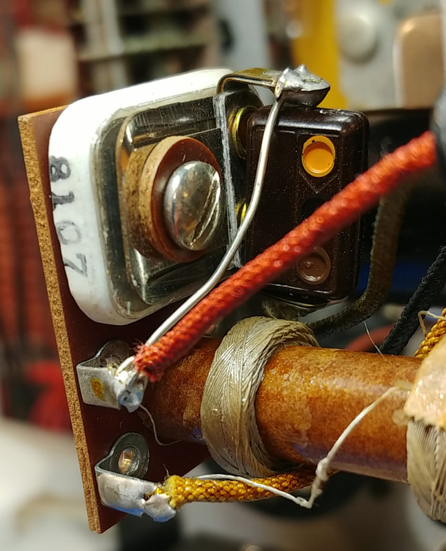
In my Supreme model 563 audio generator, which is basically the same audio generator as in the 561, the alignment screw on the L7 can is at B+ potential which can give a nasty shock and you have to be careful not to short it to the can while making adjustments. But in the 561 this trimmer capacitor has an insulating washer which wisely keeps B+ off the screw.
|
|
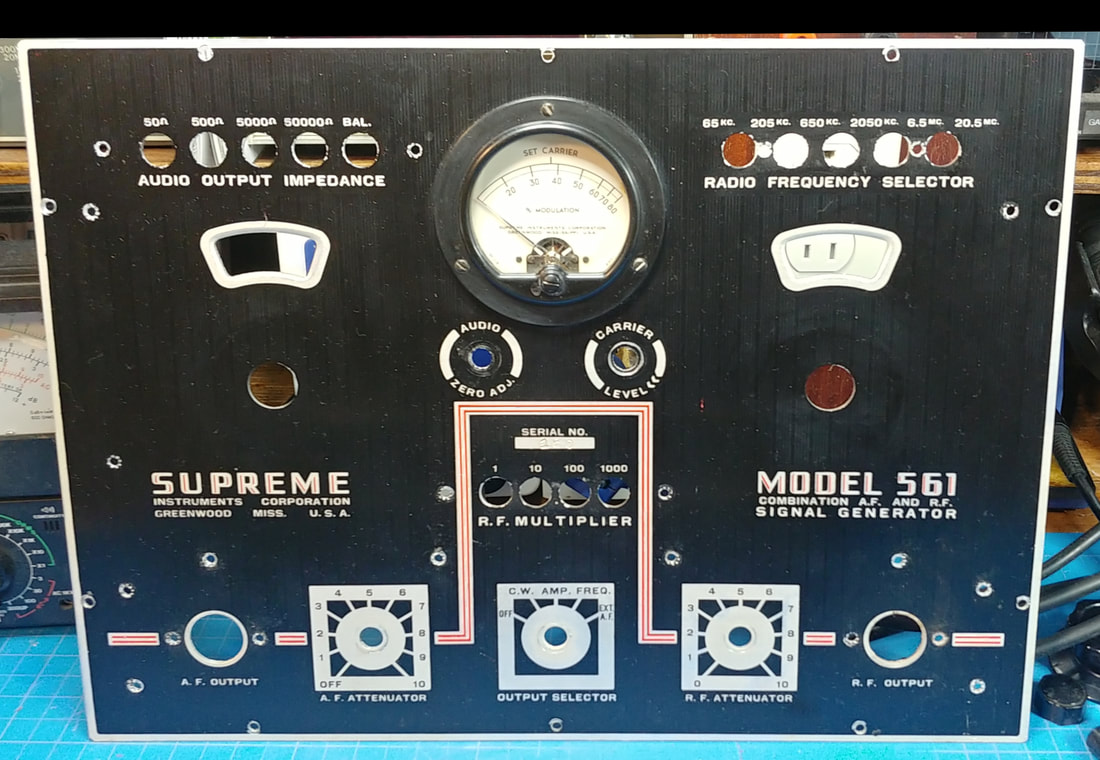
The front panel is finished. The panel, meter and knobs have been cleaned, polished and waxed. Old, oxidized control hardware has been replaced and flat washers added to protect the panel.
The black oxide fillester head screws were cleaned, and reblacked as needed. The internal lock washers under their heads were removed because they were digging into the front panel finish, but all the screws, except the ones for mounting the pushbuttons, have lock washers under the nuts anyway. And the oxidized metal on the AF and RF output connectors was cleaned and polished. |
Once the tubes are tested and reinstalled it'll be time to power up on my combination isolation transformer, variac and dim bulb tester.
|
Another bump in the road. All the tubes checked OK, and on first power up the AF generator works and zero beats no problem, but there's no RF output.
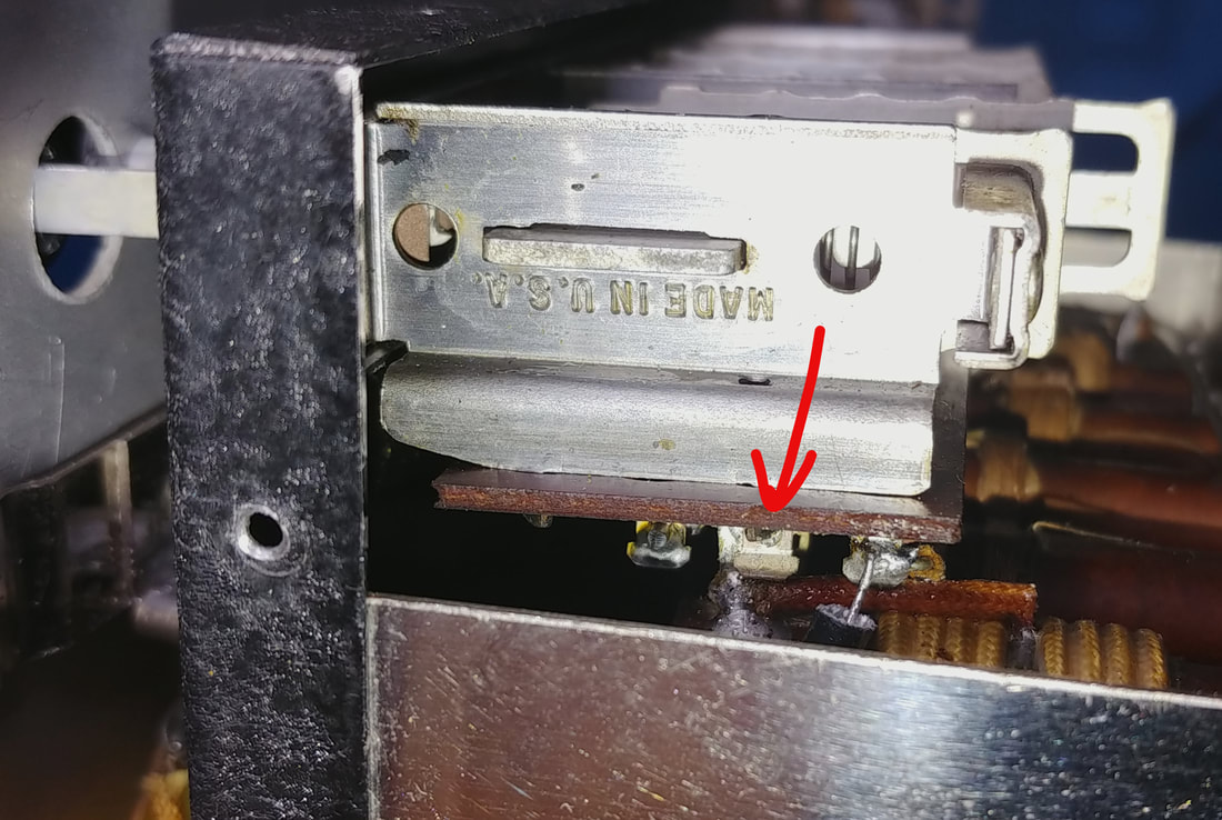
While troubleshooting the RF oscillator circuit I found the cathode resistor was not being connected to the coil tap through the Frequency Selector switches. Turned out to be a bad solder joint (arrow in photo). I wonder how long it's been like this? It looks like it could be a factory slip up that might have worked originally, and failed over time as the connection oxidized and got dirty. |
|
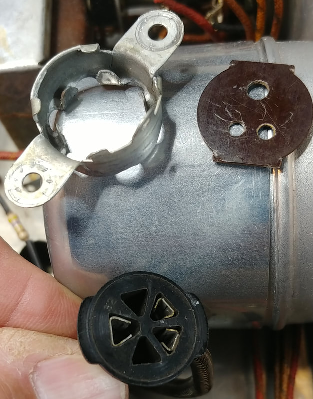
The contacts of the RF output jack are intermittent but to tighten them up requires disassembling the socket to get to them. To open the socket two tabs on one side of the metal shell have to be bent out to release the Bakelite insert.
Now there's both AF and RF output, and all the controls seem to be functioning, so I can move on to calibration. |
|
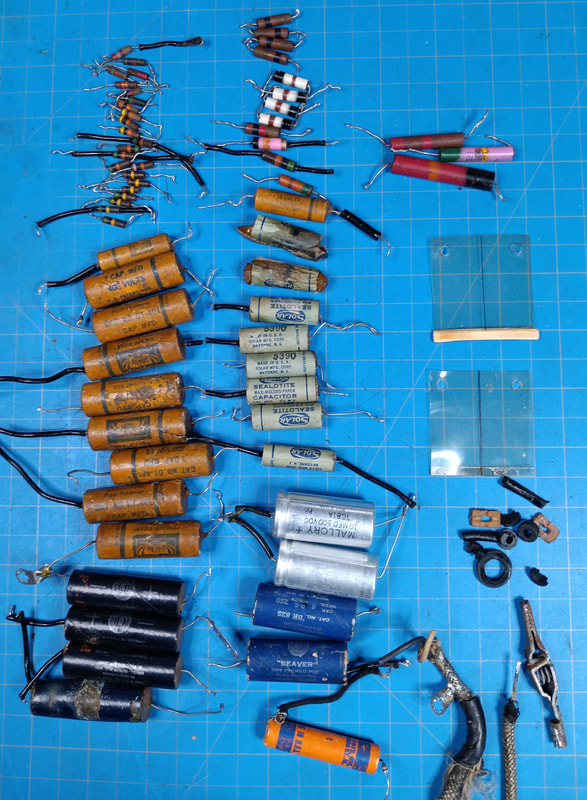
A summary of the parts replaced includes 38 resistors, 18 paper and foil capacitors, 9 electrolytic capacitors, and various miscellaneous parts like rubber grommets and switch bumpers, dial index hairlines, the power cord, and the output test cable.
A few parts were added such as the fuseholder and fuse, flat washers under all the shaft nuts on the front panel, and a polarized line plug. |
The first step in calibrating the 561 is to set meter zero for both the AF and RF voltmeters. Zeroing instructions are in the manual, but as I discovered, the procedure for adjusting the RF zero doesn't work. It's written as if there is a switch on the RF Attenuator control to disconnect the RF output from the RF Attenuator, but there is no such switch, and turning down the attenuator to 0 doesn't reduce the voltmeter reading. Maybe it was written for the original 561 without the Carrier Level control.
I also noticed in the catalog for the updated 1947 metal cabinet model 561 that the two holes for accessing the voltmeter adjustments are gone. In the 1948 model 666 manual there is no mention at all about adjusting meter zero, but the two holes to access the adjustment pots are there.
In this 561 I zeroed the RF voltmeter by shorting the RF signal to ground using a 0.0015uF capacitor at the grid (pin 5) of 6F8 V6 and then adjusted R-7 for zero.
Something not in the alignment instructions is how to calibrate the percent of modulation, and set the carrier level reference mark to the correct RF voltage. R-55 is the adjustment for the modulation percentage and R-34 sets the carrier level voltage.
I don't see any reference in the manual or alignment instructions that specifically states what voltage corresponds to the carrier level mark. The only clue I found is a sentence in the manual's introduction that says the RF output is from 1/2 to 100,000 microvolts, so I'm assuming the carrier level mark is calibrated at 100,000 microvolts RMS. Using Band A, I set the Carrier level control to the correct RF output voltage with a digital oscilloscope and adjusted R-34 to set the needle at the Carrier Level mark of the meter. That puts the trimmer right about the middle of its adjustment range.
The carrier level is spot on over the first three bands. Across the upper two ranges the output voltage measurements do drop slightly under 100,000 microvolts when set to the carrier level mark, maybe due to the frequency response of the meter or the like. It's nothing I'm going to worry about.
I also saw a note in the model 666 manual stating the maximum output level in the 666 would drop too low to set it to the carrier level mark above about 8MC. But after buying and restoring a model 666 I don't see any real operational difference between them.
The modulation percentage was calculated by formula from readings taken with an oscilloscope. R-55 was adjusted accordingly and the adjustment was repeated at different percentages just to verify and fine tune the setting. The calculations using the scope got the accuracy to within 10% or better.
|
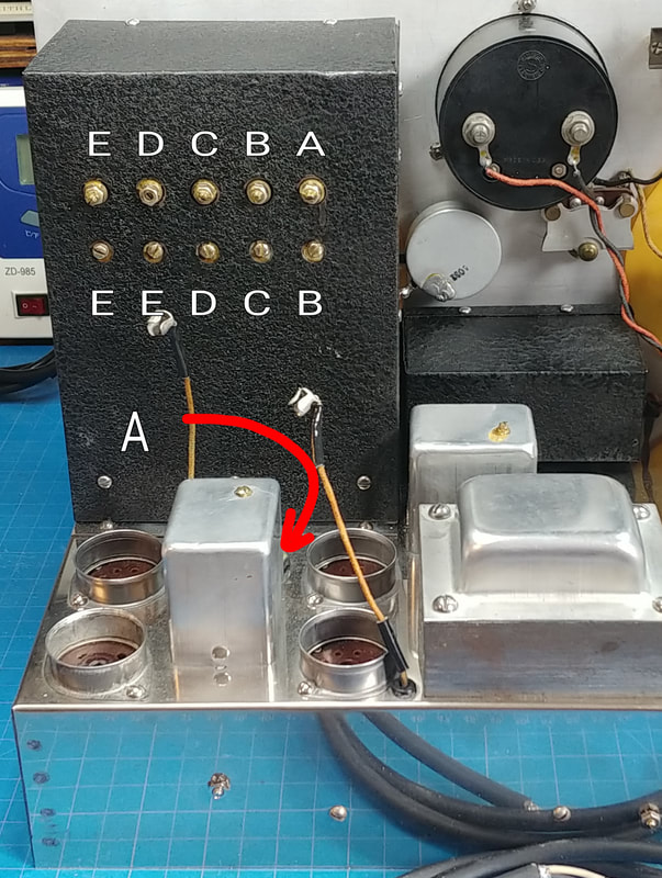
The band alignment adjustments are all on the rear of the RF box except the Band "A" trimmer, which is on the chassis beside the 6K6. However the coils and trimmers are not in line as one might expect, but are offset as shown in the labeled photo. The coils are the top row. The two trimmer capacitors marked "E" are in parallel. The alignment is done in order from Band "A" first to Band "E" last, and for Band "E" only the trimmer next to "D" needed to be adjusted.
The alignment procedure was written back in the days before frequency counters were common, but I gave them a try by using my BC-221 frequency meter as the xtal standard and my Radio Shack DX-160 as the receiver, since it has a longwave band and a BFO. The alignment using the receiver is accurate, but it's simpler and quicker to just use a frequency counter. |
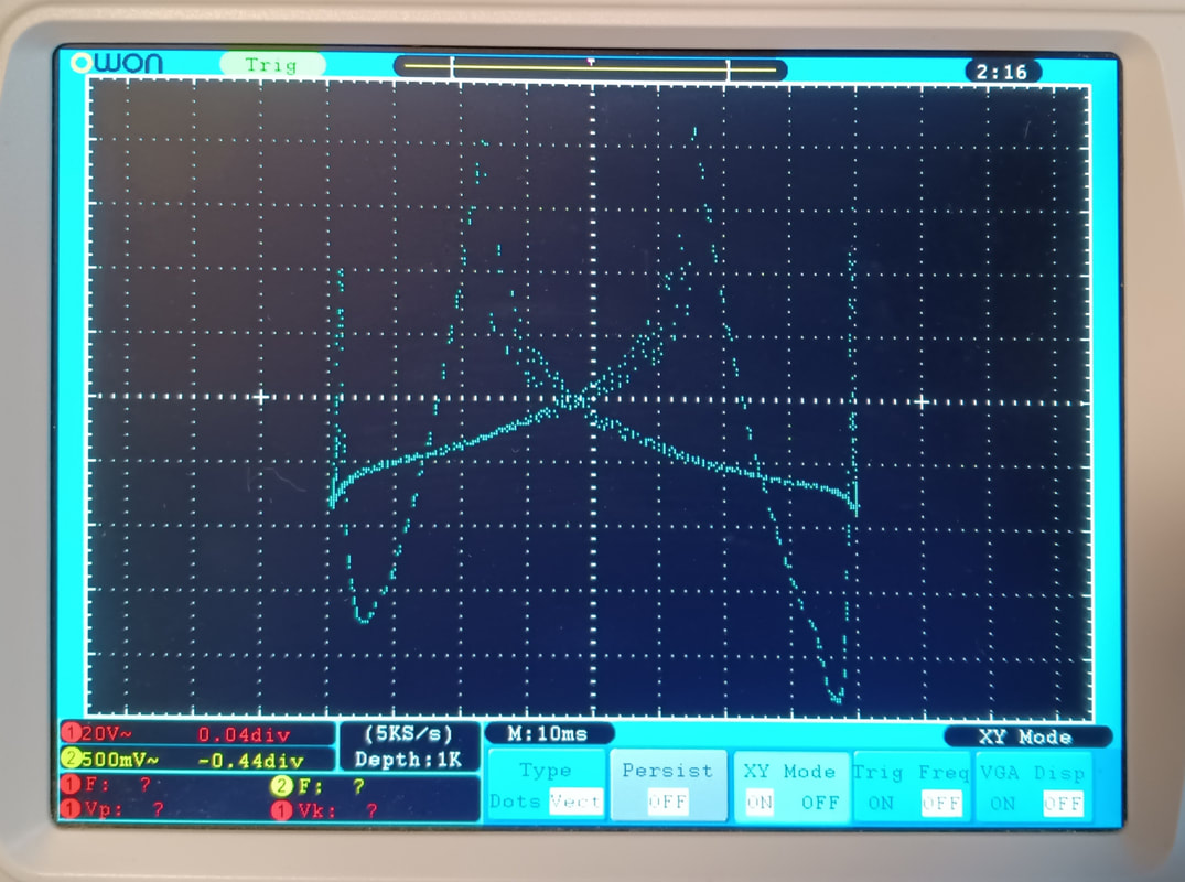
The last step in the alignment procedure is adjusting trimmer #4 for the frequency modulator. The 1000KC RF signal from the generator was connected to the antenna cable of the TRF receiver in my model 562 Audolyzer and the dial set to 1000KC. The demodulated signal from the Audolyzer's scope out jack was patched to the Y channel of the scope. The generator's Audio Out cable (for the timebase when in Freq mode) was connected to the X channel. The timebase signal is the 561's 6.3VAC filament voltage so care must be taken not to short the leads together or bad things will happen. The oscilloscope was set up in XY mode and the trace positioning and V/Div adjusted to display the resonance curve on screen.
The first image is after the initial setup at 1000KC, and before adjusting the trimmer. The peaks are not coincident.
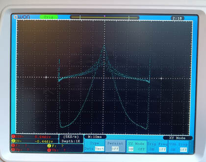
The second image is after adjusting trimmer #4. In this case it took one full turn CCW to adjust the peaks so they coincide. Checking the curve at 2000KC as per the instructions shows basically the same coincident curve but at a slightly lower amplitude.
Refinishing the cabinet and cleaning the hardware is done and the 561 is now back in its cabinet. It's looks really good and is working great. The old rubber feet were mashed flat and are rock hard, so I installed new ones. They're the last parts to be replaced.
To refinish the cabinet the patent label on top had to be removed. I managed to get it off in one piece and will scan, touchup and print a new one as soon as I get some silver paper to print it on. The 561 is now going on my work bench beside the Vedolyzer.
To refinish the cabinet the patent label on top had to be removed. I managed to get it off in one piece and will scan, touchup and print a new one as soon as I get some silver paper to print it on. The 561 is now going on my work bench beside the Vedolyzer.
Page created 11/06/2021
Last edited 6/7/2022
Last edited 6/7/2022

