Eddystone Model EC-10 MK I Transistorized Communications Receiver
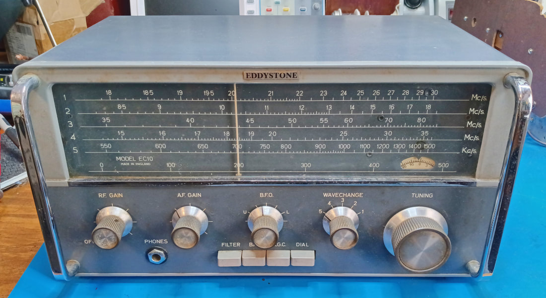
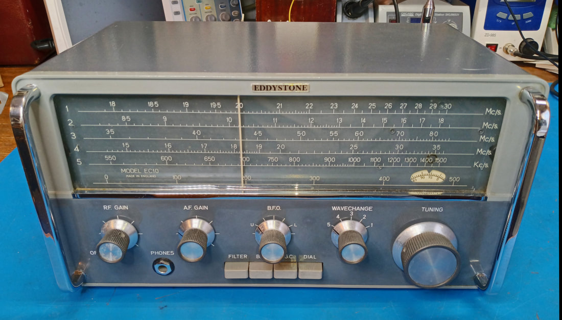
This British set by Eddystone was first introduced in 1963. It's a fully transistorized general coverage communications receiver using 10 germanium transistors plus five diodes, and is battery operated. It covers from 550KC to 30MC in five bands.
The EC-10 was among the first fully transistorized communications receivers to appear in the very early 1960's, and the second* such set offered by Eddystone. It's my first Eddystone receiver and I'm impressed with its quality.
This is a hamfest find. The moment I spun the weighted tuning knob with its 10:1 gear reduction across its nine inch dial, I was hooked.
* (The first fully transistorized Eddystone receiver was a 12-transistor model 960 that debuted in 1962, and was quickly followed by the much more successful 10-transistor model EC-10 in 1963. Only 150 model 960 sets were ever produced, but over 16000 EC-10 MK I and MK II receivers were sold. Check out eddystoneusergroup.org for more info on Eddystone receivers.)
|
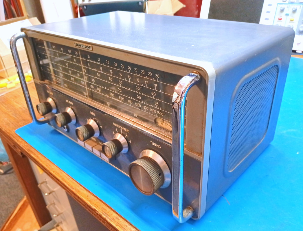
The radio is in nice condition overall. It's a bit dirty, and there are a few scratches and chips in the paint, but nothing too difficult to deal with, and it doesn't appear anything is missing or broken.
The knobs on this set are different from the original style used in 1963, and match the type shown on the front cover of the EC-10 manual from 1968, so this EC-10 must be closer to a circa 1968 vintage. |
|
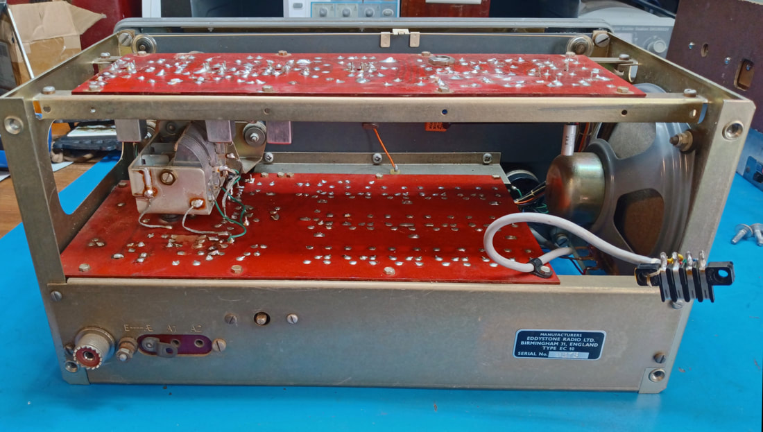
All the circuitry is on two PCBs. It has been worked on and some of the electrolytic capacitors have been replaced, but not all of them. I also see that one of the original OC171 germanium transistors, TR1 the RF amplifier, has been replaced. I wonder if it developed "tin whiskers" or if someone was trying to make the radio "better".
The radio does work, but there's a lot of static noise, and popping and cracking going on, which means there are some noisy components hiding in there somewhere. |
|
It's amazing just how much noise is coming out of the speaker with the RF and Audio Gain controls turned down to minimum and no antenna connected. I know the audio section supposedly hisses, but this is seriously loud.
Other oddities I'll need to investigate include the RF Gain having a very limited adjustment range and needing to be left at or near maximum mostly, the BFO frequency is misadjusted, and there is a loud squealing on parts of a couple of bands which does require reducing the RF Gain to eliminate it. Turning on the AGC actually increases the volume, and the dial calibration across all the bands is off, too. |
I decided to tackle the audio section first to cure the static storm coming out of the speaker. Since the Audio Gain control feeds TR7 I started there and disconnected the transistor to see what would happen. The audio amp immediately went quiet indicating the issue was associated with the first audio stage. I tried a replacement transistor for TR7, but the static was back and as loud as ever, so it wasn't the transistor.
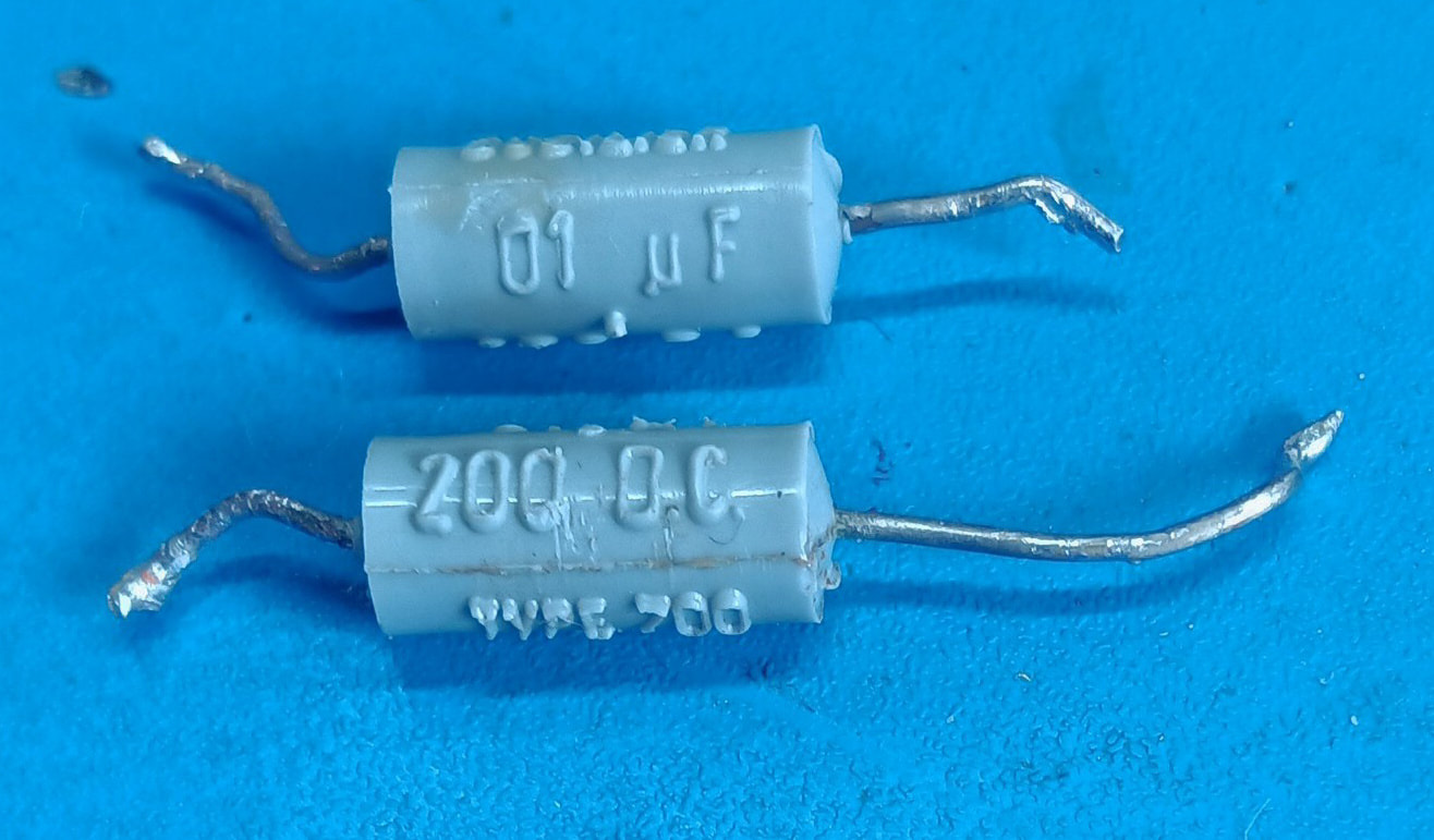
Next all the associated resistors were removed and checked, and several were out of tolerance. I also noticed in the parts list that C74, which couples the audio from the gain control to the base of TR7 was listed as a "metalized paper" capacitor, which sounds like a fancy version of the notorious waxed paper and foil caps in vintage AM radios. I pulled it and sure enough it failed a leakage test on my capacitor tester.
I replaced the out of spec resistors and the bad cap and reinstalled the original OC71 transistor. The audio amp is now as quiet as a church mouse. I checked the replaced parts on the noise test function of my Eico signal tracer but could not determine exactly which of them was causing the static roar.
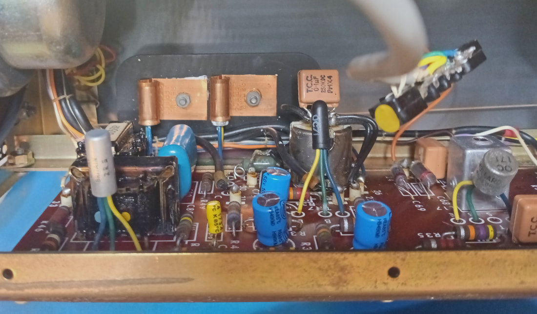
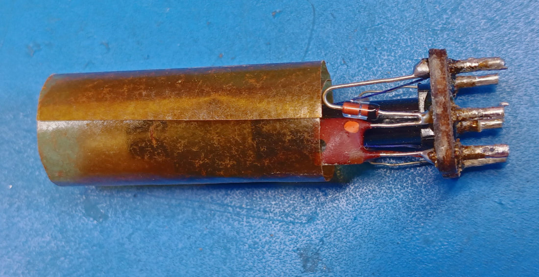
In the parts list there are three of these 0.01uF metalized paper capacitors, C30, C65, and C74 listed. Besides C74, I also changed C30 because it tested bad, too, but capacitor C65 is incorrectly listed as metalized paper in my set. It is inside IFT3 along with the detector diode D2 and is actually a ceramic cap.
|
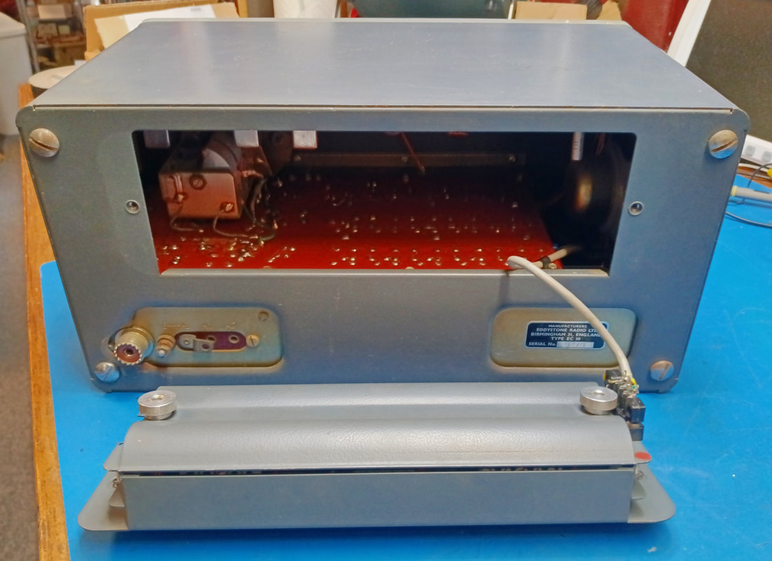
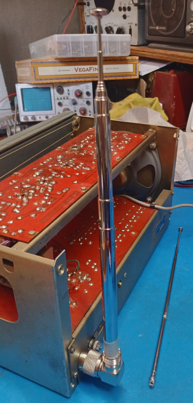
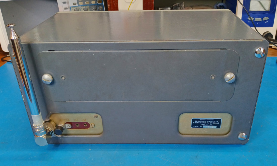
My second mod of sorts. The previous owner of this radio had attached a right angle PL-239 adapter with a small 24" whip soldered into the center socket of the adapter. It looked a bit wimpy on the set, but it's a good idea for attaching a collapsible whip antenna, so I unsoldered the little antenna and soldered in a metric screw that fits a 38" replacement "RC Hobby" antenna from my local Radio Shack (yes, independent Radio Shacks still exist). Now, that's an antenna. I collapsed it down to get it all in the picture.
|
|
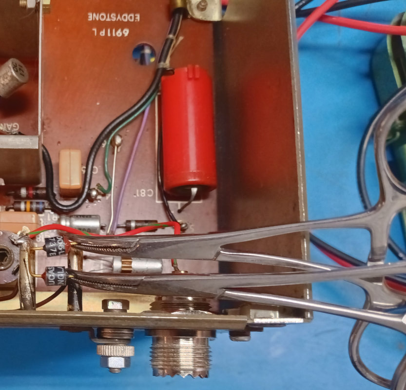
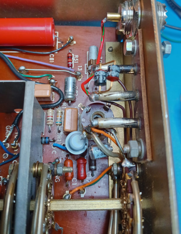
There are two back-to-back diodes in the antenna circuit that were unsoldered and checked. Also, the orange 350uF electrolytic capacitor C81 was pulled and failed a leakage test, so it was restuffed with a replacement cap to keep it looking original. And resistor R51 (just below the electrolytic) is out of tolerance and needs replaced, too.
|
|
Next I took a look at the RF amp and why the RF Gain control only worked at the very top end of the control. The original OC171 had been replaced with a GT320A germanium transistor, and unfortunately, whoever did it messed up some of the PCB pads in the process. So I pulled the transistor and replaced two pads. A third for the shield wire was also missing but I didn't replace it since that pad is not used with the GT320A.
While the transistor was out I checked all its associated resistors and two bias resistors, R1 and R2, were out of tolerance. After replacing the resistors and reinstalling the transistor, the RF Gain control now has a wider range of control over signal levels, and it cleaned up some distortion, too, so looks like it was a biasing issue. |
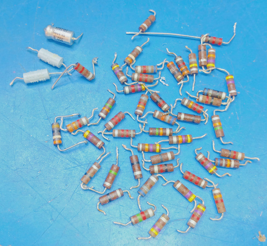
After the problem with the audio amp and the bias being off in the RF amp, I checked all the resistors in the set. I found 32 that were out of tolerance and replaced them.
|
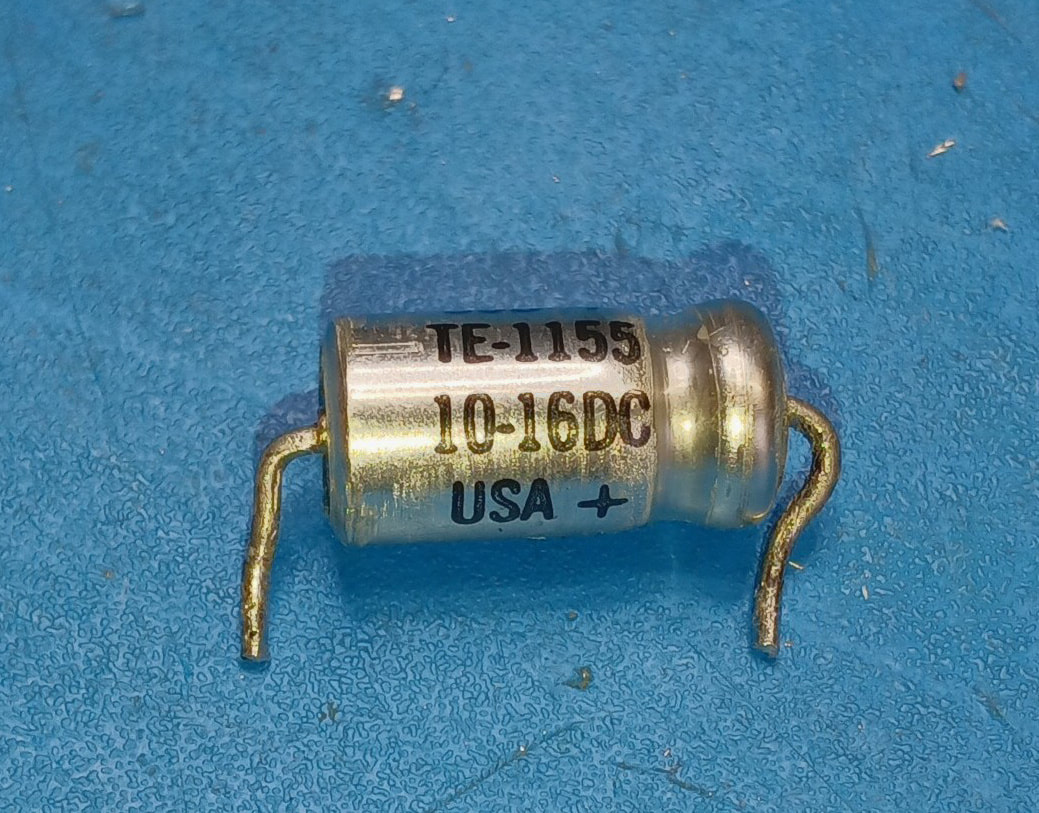
The only electrolytics I haven't replaced are two of the three Sprague axial 10uF caps because they are very good quality and right at the moment I don't have anything better to replace them with. They both passed testing with flying colors.
I did replace the third Sprague 10uF, C63, with a non-polarized capacitor because I read online that the AGC can go positive on strong signals, which reverses the polarity on this electrolytic. I checked this set's AGC and sure enough it does reverse polarity, most notably when the AGC is off. |
|
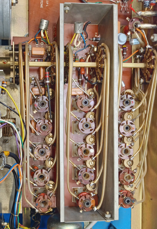
The static roar is gone, the RF Gain works, and the AGC, too, so now so it's time for an alignment. Some of the coil cores are at the top of the forms and some are at the bottom, so it sure looks like someone has messed with the alignment.
Band 1 is dead and Bands 3 and 4 are just static so I'm sure these bands are badly misaligned. The other two bands receive stations, but the alignment needs to be redone. Band 4 has a lot of static with no antenna attached, unlike the other four bands which are relatively quiet. Checking the schematic for what components are specific to Band 4, I saw there was a 220Ω resistor across the secondary of the mixer coil. It checked in spec but I replaced it anyway, and now band 4 is as quiet as the other bands when no antenna is connected. |
|
These old carbon comp resistors keep popping up as the main issue I'm running into with this set, so I've decided to just replace all of the remaining ones. There's only about a dozen left anyway, so they're out of there.
A summary of everything else replaced so far includes the two leaky metallized paper caps, plus the large electrolytic C81, the AGC cap C63, and the four 100uF electrolytics. The 100uF caps had already been replaced by someone before me, and they were OK 85°C caps, but I swapped them again for long life Nichicon 105°C electrolytics. |
|
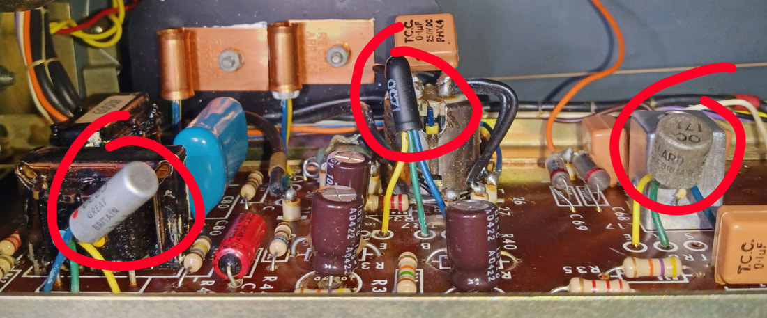
There are three types of germanium transistors in this radio, the OC71 circled in the center, the OC83 on the left, and the OC171 on the right. Some early germanium transistors, such as the OC171, suffer from a defect known as tin whiskers, which are tiny filaments of tin that can grow inside the transistor and short leads to each other or to the tin-lined can.
|
I've already had the radio go abruptly silent twice and I finally discovered the first OC171 IF transistor apparently has tin whiskers intermittently shorting it. Giving it a sharp snap with my fingers got it working again for now, but it will probably happen again in time, so I'll either have to give the OC171's the high voltage treatment recommended online, or replace them as necessary.
I've ordered some Russian-made PNP germanium transistors from overseas and when they arrive I'll have a second look at replacing the RF amplifier transistor with a more correct replacement, and also check all the OC171 transistors for leakage from tin whiskers.
I've ordered some Russian-made PNP germanium transistors from overseas and when they arrive I'll have a second look at replacing the RF amplifier transistor with a more correct replacement, and also check all the OC171 transistors for leakage from tin whiskers.
All back together and sounding much better than when I bought it. The bands are aligned and all functions work. The only thing I'm still debating is adding an AC power supply, but for now I will leave it as just a battery set.
Page created 8/7/2023
Last edited 8/18/2023
Last edited 8/18/2023

