
I've been working from makeshift workbenches ever since our move a couple of years ago. Basically they're just folding tables set against a wall with wall-mounted shelves for test equipment to set on. They're too low and too narrow so I've decided it's time for a real radio workbench.
Building a Radio Workbench
|
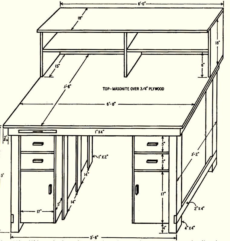
I found plans for a bench, that's just what I had in mind, in a Gernsback publication from 1953 titled "Radio and TV Test Instruments". Chapter 21 describes "A Workbench for Radio and TV".
The benchtop is 6-feet long and 42-inches wide, with a top shelf 18-inches wide and a middle shelf 15-inches wide. Allowing for the shelves, this leaves a clear working area of 6-feet by 27-inches. And soldering irons and other smaller necessities can go under the shelves, out of the way. It's twice the workspace my tables had, especially after making room for the soldering irons and test equipment. The bench work top is 39-inches high which is just right for standing or sitting in a swiveling workbench chair. The bench will also have plenty of outlets, and a master ON/OFF switch, to make sure no equipment or soldering irons are accidentally left on at the end of the day. |
Since the bench will be too large to go through a doorway, it is completely assembled using screws so the shelves and legs can be removed should it ever need to be moved.
Because of the height of the bench and shelves, it's too tall for my current workspace's sloped ceiling up in the garage loft, so I created a new lab downstairs, in the area where the observatory computers were originally going before I decided to build a seperate observatory building.
Because of the height of the bench and shelves, it's too tall for my current workspace's sloped ceiling up in the garage loft, so I created a new lab downstairs, in the area where the observatory computers were originally going before I decided to build a seperate observatory building.
|
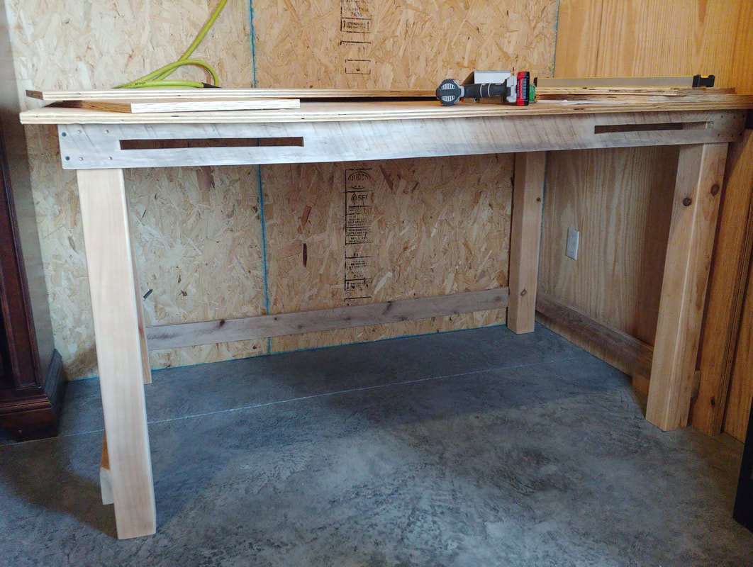
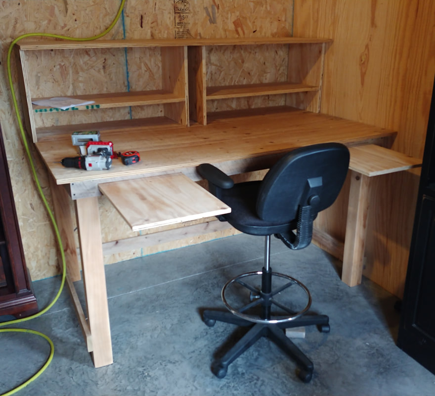
All the parts to construct the basic bench were precut, sanded and then assembled. The top and shelves are 3/4-inch plywood, which is the most expensive item I purchased. The 4x4-inch legs are leftovers from the stair rails in the cabin, and the 1x4-inch pieces are leftover poplar lath from the metal roof install.
The two slots in the front are approximately 15-inches wide for pull-out shelves to lay schematics and such on. They should come in very handy, which is why I decided to add one on each side. The original plans only called for one on the left side. The not-so-square angles are caused by camera distortion. |
|
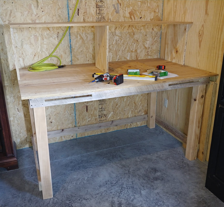
Starting to piece together the shelves. In this photo I'm short one 18x15-inch piece of plywood for the center support column. The column will be 4-inches wide on the inside and 18-inches tall, and is where the master power switch and the unswitched outlets will be located. 4-inches was a little tight, but worked. If I did it again I'd probably make it 5 or 6-inches wide.
I have to drill entry holes in the column sides for the outlet strip power cords on each shelf, plus a hole in the top shelf for its power cord, and one through the bench top at the back for the master power cord to go down to the wall outlet. The unswitched outlets on the panel are for such things as charging batteries overnight. With these there's no need to leave the bench power on all night. |
|
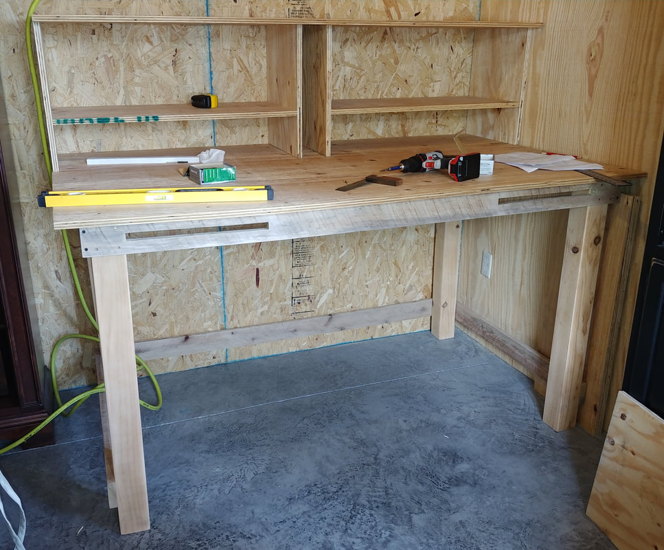
The shelves are mostly complete now. The diagram shows a single center support but the text in the book describes the column. In the text the column holds the variac, but mine will be wall mounted because I also have a dim bulb tester. I still need to make the front cover for the column, which I'll do when I start on the wiring, but next I'll fit the two pull-shelfs.
|
|
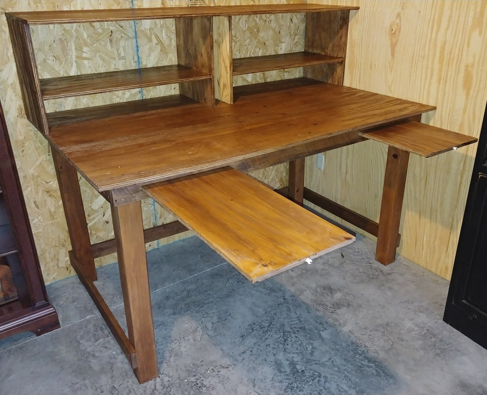
l installed the pull-shelfs and just need to add knobs to the front edges. The pull-shelf in the original design was 17-inches wide and 30-inches long, but I had a 6-foot long piece of plywood left from cutting the shelves that was just shy of 15-inches wide so I used it instead. Saved me from buying another sheet of plywood. Since the piece was 6-feet long I cut it in half for two pull outs instead of one. With the shelfs fully extended there is a bit over 30-inches of usable space of the 36-inch board length. The rest is for support and blocking.
The pull-shelfs have stop blocks to prevent them from being pulled out or pushed in too far. They ride on a bottom board that supports the shelf when pushed in, and have spacer blocks attached to the top rear so they can't drop down when pulled out. |
Cutting and assembling the bench has taken the better part of three days. I don't think I'll have time to build the cabinets right now, so I will concentrate on stainiing the bench and then completing all the wiring. Then I can start using it while working on the cabinets.
|
I decided to do a MinWax poly and stain all-in-one finish on the bench. This is just the first coat. It will need at least a second coat of poly but I have to buy some first. Next I need to work on the electrical wiring and installing the outlet strips.
|
|
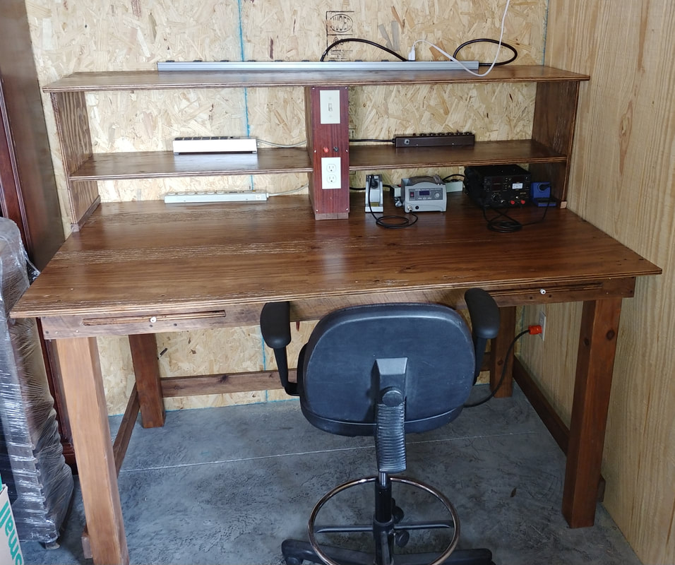
The center column wiring is finished. I cut a piece of mahogany plywood (from an old console cabinet) to make the panel. I placed the Master ON/OFF switch at the top and two unswitched outlets towards the bottom. At the very bottom, on the inside of the panel, is a switched duplex outlet for the shelf power. There are also two banana jacks in the center of the panel for an outside antenna connection.
I've installed five heavy duty metal outlet strips: a 10-outlet strip on the top shelf, and 6-outlet strips on both sides of the middle shelf and on the table top on each side of the column. That gives me a total of 34 switched outlets, not that I'll need that many, but it provides flexibility to place my test gear where I want and always have an outlet available. The master power switch controls the duplex outlet inside the column. The top shelf 10-outlet strip and a heavy duty 4-outlet strip, mounted inside the column, plug into the duplex outlet. The other four outlet strips on the shelf and table top plug into the 4-outlet strip. |
When I built the shelves I used the dimensions in the plans, which left a height of 6-inches from tabletop to the bottom of the first shelf. Of course this turned out to be about 1/2-inch too low for some of the things I wanted to put under there. There's always something that doesn't want to fit. So to fix the problem I added 1-inch thick oak extensions to the bottom of the shelf supports and the column. Now all the small equipment slides right under the shelf like originally planned.
|
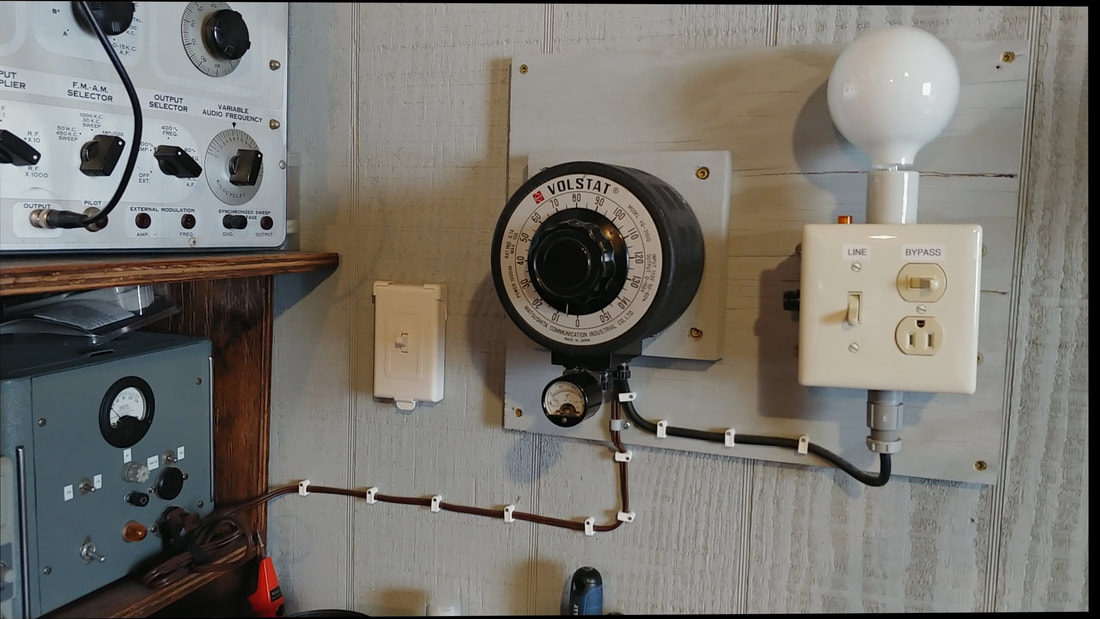
I just finished remounting the variac and dim bulb tester on the wall to the right. And the isolation transformer is on the far right of the middle shelf. I usually keep all three hooked in series: from the isolation transformer to the variac and then through the dim bulb tester. There's an outlet on it for the device under test and it also has a bypass switch to remove the bulb from the circuit.
|
|
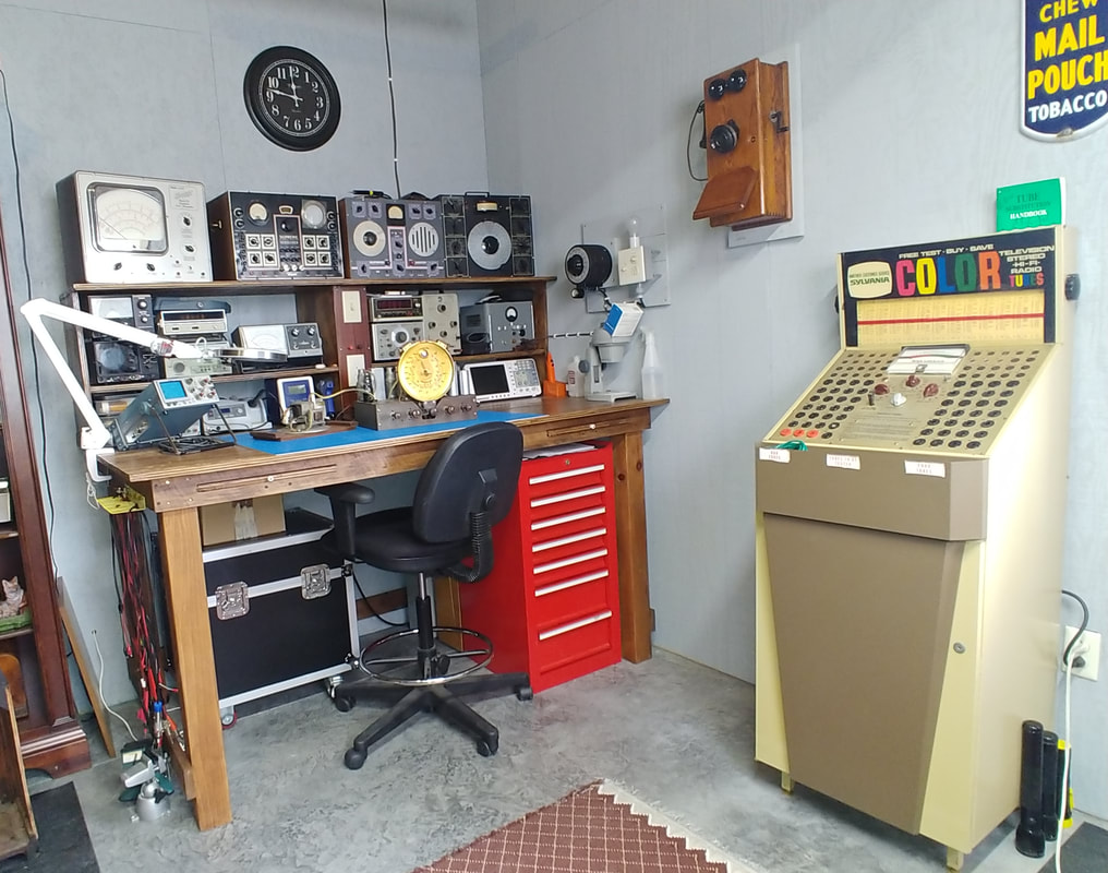
The new workspace is starting to come together. I've populated the bench with most of the equipment from the old workbenches, which I'll adjust over time as I decide what pieces are most useful. I brought my drug store tube tester down from upstairs and my TV-3 and Precision tube testers are sitting under the bench (along with my EQ-8 mount). I also purchased a 24x36-inch cutting mat to protect the bench top.
I placed my small Harbor Freight tool cabinet under the right side of the bench. It's a perfect fit and gives me seven drawers for tools. It worked out so well I don't think I will bother building the cabinets from the plans, even though I've already precut some of the pieces. I think I will also leave the left side open under the bench for more leg room. |
Page created 8/1/2020
Last edited 4/12/2021
Last edited 4/12/2021
