
SSPRO V1 Set-Point Temperature Controller Mod
I had to take separate dark frames for each imaging session because of a lack of temperature control for the thermoelectric cooler (TEC). This modification adds set-point temperature control to the camera by attaching a resistance temperature detector (RTD) to the CCD chip and rerouting the +TEC power through a solid state relay (SSR) controlled by a proportional–integral–derivative (PID) controller. The controller, using the RTD sensor input, controls the +5V power to the TEC via the SSR, maintaining the set temperature within +/- 0.1°C.
Disclaimer: Perform this mod at your own risk as it is a bit involved and there are ample opportunities to damage a working camera. Also, making modifications might lower the camera's resale value. For example, I managed to damage my camera's TEC while doing this mod and had to replace it. Fortunately my mistake only cost me about $30 for a new TEC and some heat transfer material.
The steps I took to install the mod include:
- carefully disassembling the camera (the electronics are static sensitive and should be handled properly)
- drilling a hole through the PCB into the CCD chamber to feed the RTD and + TEC wires to a connector on the back plate.
- epoxying the RTD to the back of the CCD - I used JB Kwik Weld (another option would be Arctic Silver thermal epoxy).
- disconnecting the +5V TEC wire and splicing and routing it out the chamber hole.
- soldering a new wire to the +5V PCB through hole from which the +TEC wire was removed.
- cutting a hole and mounting the new connector to the back plate of the SSPRO
- soldering RTD, +TEC, +5V TEC, +12V and GND wires to the new connector
- constructing the controller box with the PID controller, SSR and mating connector
|
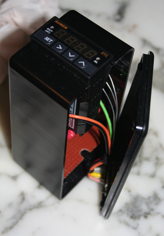
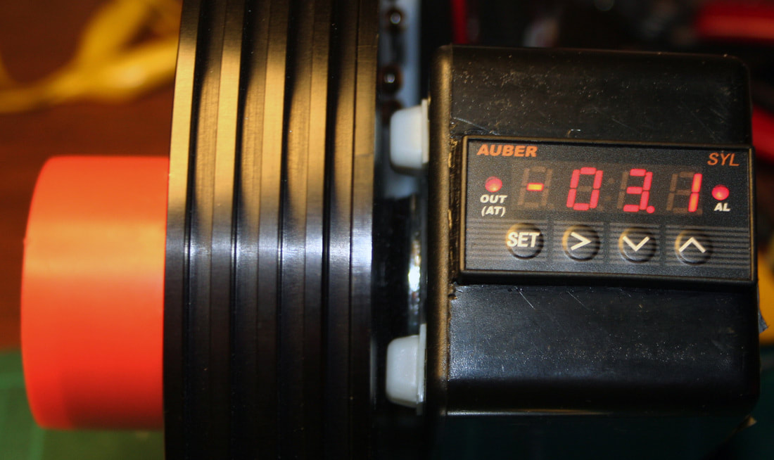
PID controller front panel. The controller is from Auber Instruments. I used a Radio Shack project box for a housing.
|
|
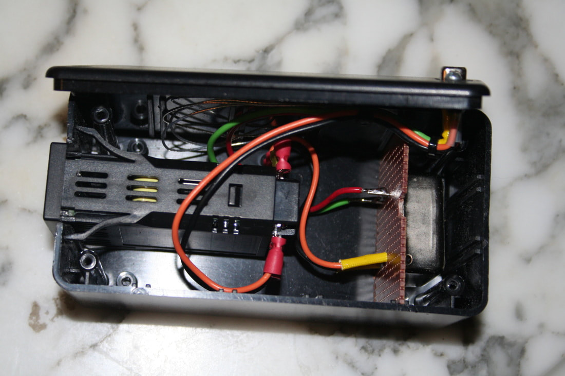
Inside the controller box - the PID controller, SSR and connections to the 9-pin connector interface.
The DC 5A SSR also came from Auber and is mounted on prototyping perf board. |
|
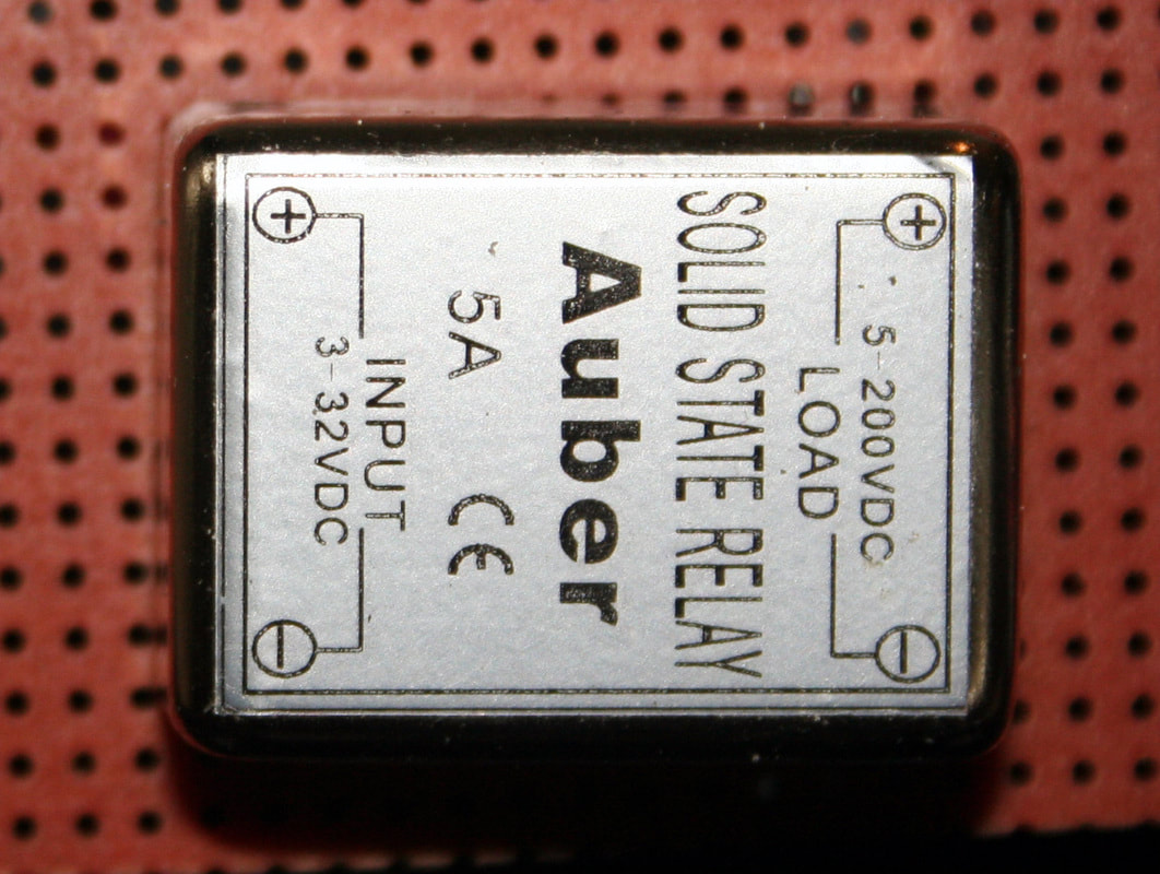
The Auber 5-amp DC Solid State Relay up close.
|
|
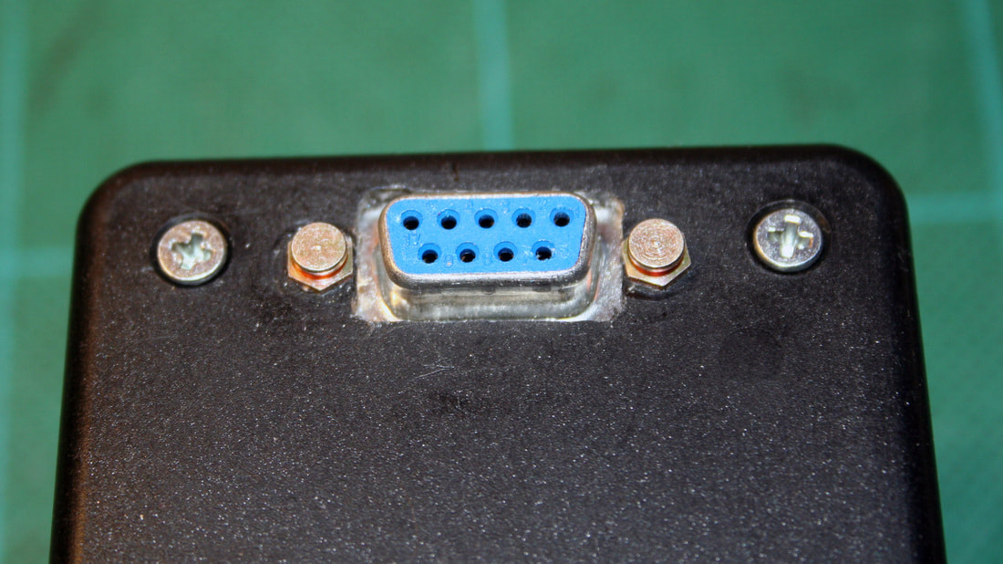
The DB-9F connects to a mating connector installed on the back of the SSPRO camera. The DB-9 passes the RTD, SSR output and 12VDC for the PID controller between camera and control box.
|
|
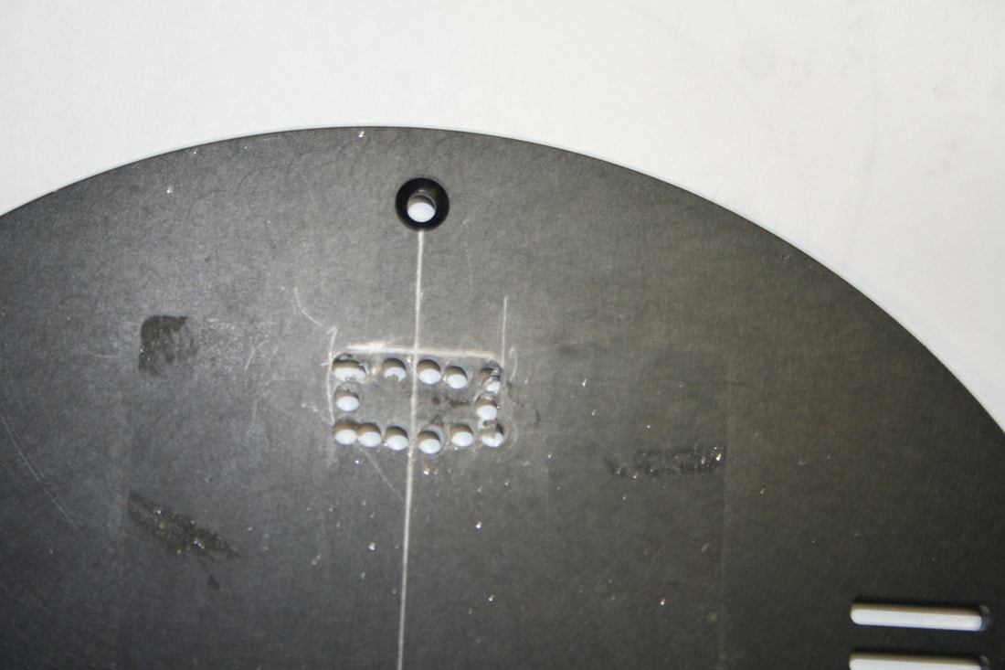
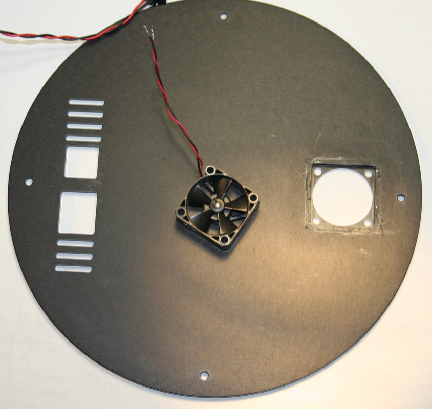
To add the DB-9M connector to the back plate of the camera I marked the outline of the connector and drilled small holes around the outline.
I placed the connector on the right side of the camera plate (as viewed from the back with the fan at top) because there are components on the PCB's left side that were in the way. |
|
I cut the perforated section out with my rotary tool and finished up the hole with jeweler's files.
|
|
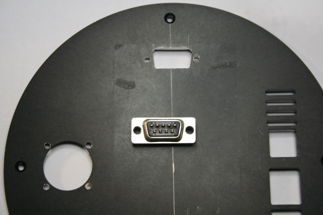
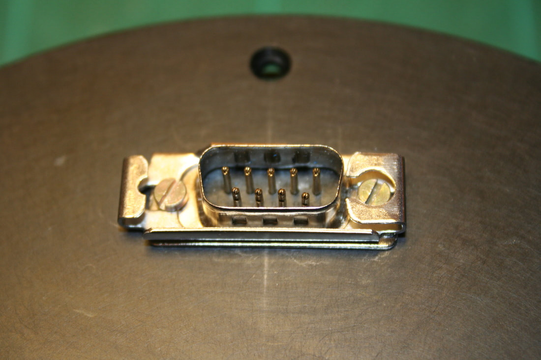
I used a slide lock on the DB-9M to lock the connectors together. Because of the thickness of the back plate the DB-9M had to be mounted on the outside of the panel to make all the spacings work out.
|
|
Slide lock posts go on the controller box side DB-9F connector. The slide lock and posts came from Digi-Key.
|
|
This is not technically part of the mod but while I was at it I drilled four holes to securely mount my low vibration replacement fan. Originally the fan was only hot glued in place which seemed a little tacky (pun intended). I tapped the fan's mounting holes for a 6-32 thread and then screwed the fan to the panel. Because of the fan's thickness it comes very close to internal components, which ruled out using long screws with nuts on the inside. Probably why it was hot-glued in the first place.
This is the low vibration Copal replacement fan recommended by a member of the StarShoot Pro Yahoo Group. |
|
The TEC power wires - Red (+5V) and Black (GND)
|
|
I managed to damage my TEC by trying to solder directly to it which is a VERY BAD idea (see the pics below on replacing the TEC with a new unit). I could have avoided the extra work and headache by doing this the simple way, just splicing the wire.
I think the best way to solder a longer wire to the TEC is just snip the TEC's red wire where it solders to the board, strip some insulation insulation off, temporarily clip a heatsink tool or hemostat to the wire close to the TEC to absorb excess heat, and then solder a longer red wire to the short TEC wire. Pushing some heat shrink tubing over the soldered connection would protect it from shorting to anything. Easy peasy - hindsight is always 20/20. |
|
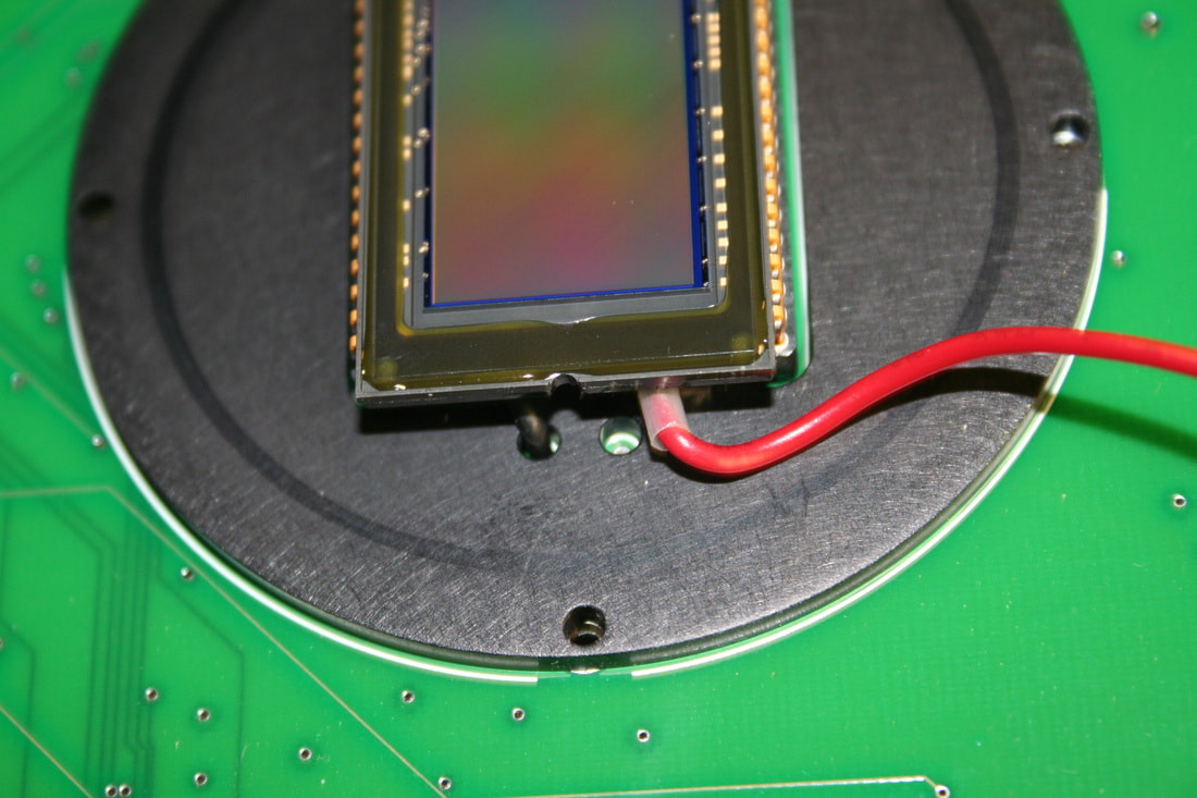
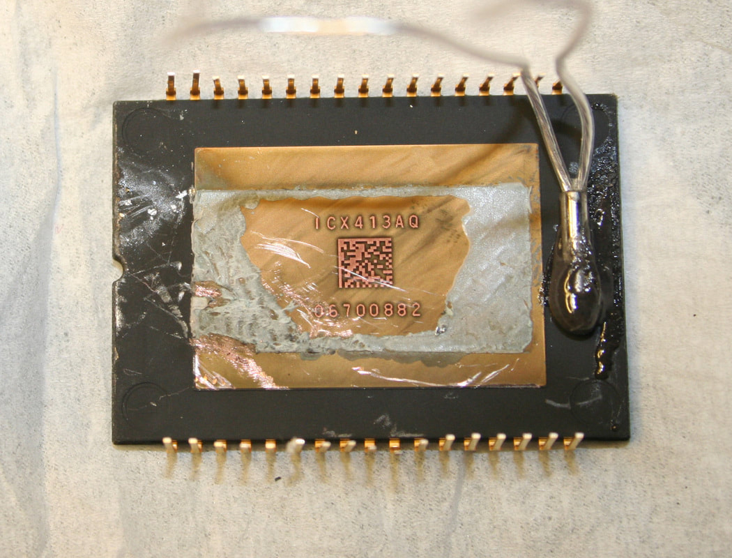
The RTD sensor is epoxied to the back of the CCD sensor with JB Kwik Weld epoxy. It responds quickly and the temp agrees with the IR temp reading I took while I had the camera disassembled. Silver Arctic epoxy might be an even better choice for this.
This miniature RTD sensor came from Auber Instruments. |
|
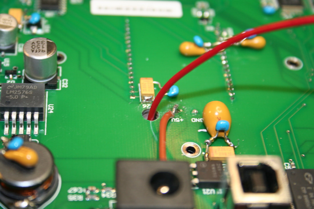
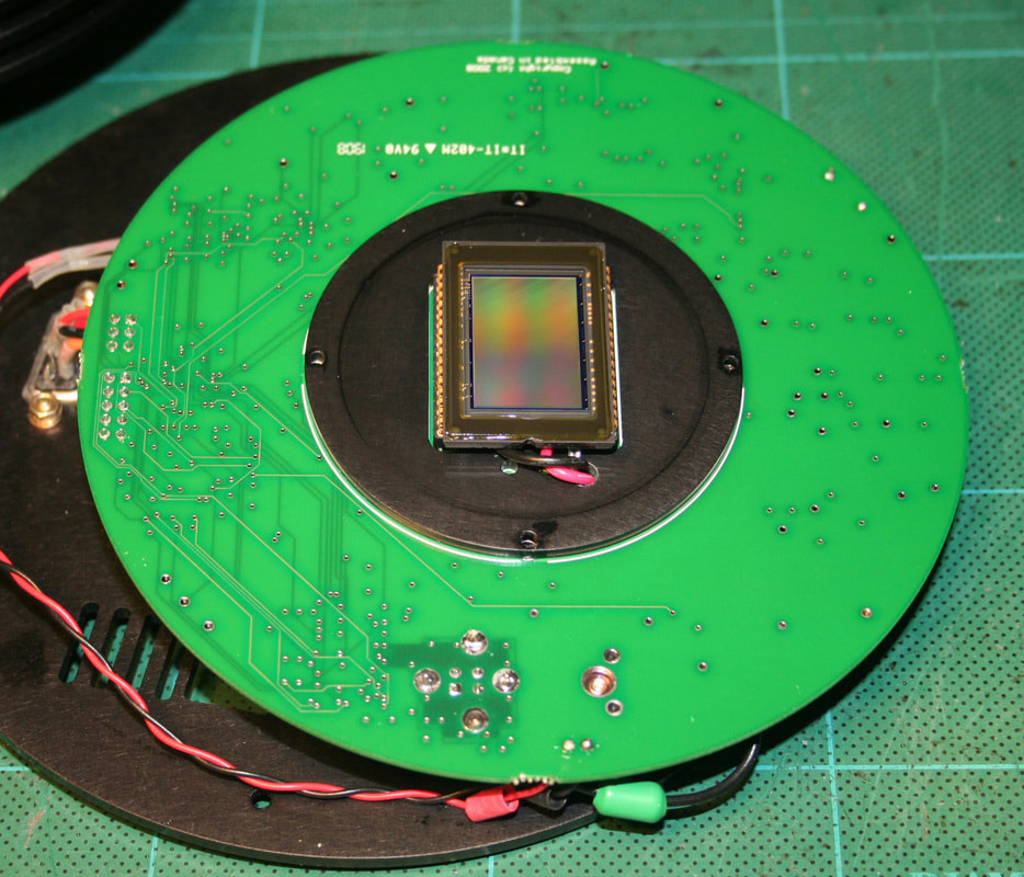
I drilled a 5/32" hole through the PCB and cold plate to the left of the TEC +5V through-hole pad. The picture describes it better than words. There is a trace on layer 2 between the +5V pad and my hole so I had to be sure to miss that.
I read somewhere that starting and stopping electric motors in close proximity to CMOS circuits might induce currents into the circuits and damage them. In case this is true I set up the drill press and did a dry run drilling the hole, and then removed the board from the proximity of the drill press to start it up. I then placed and drilled the hole and removed the board before shutting off the motor. Just in case... This is obviously one of the more dangerous steps of the mod. |
|
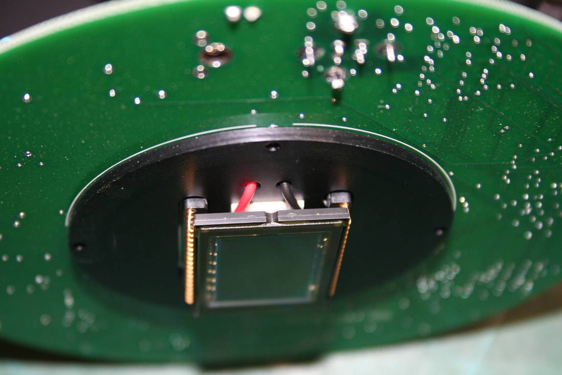
The CCD sensor side of the hole in the PCB comes through the cold plate. It was a tight fit, finding an open area that was inside the chamber wall and not under the CCD sensor, or close enough for the bit to hit the sensor, and that was also free of any copper traces.
I spent hours studying the board's layout trying to assure myself I was missing any traces on internal layers. This is the spot I decided was my best shot. The camera still works so looks like I guessed right. Since I had to replace the TEC I fed both the black and red wires from it through the access hole along with the RTD wires. I soldered the black wire to ground at the power connector. |
|
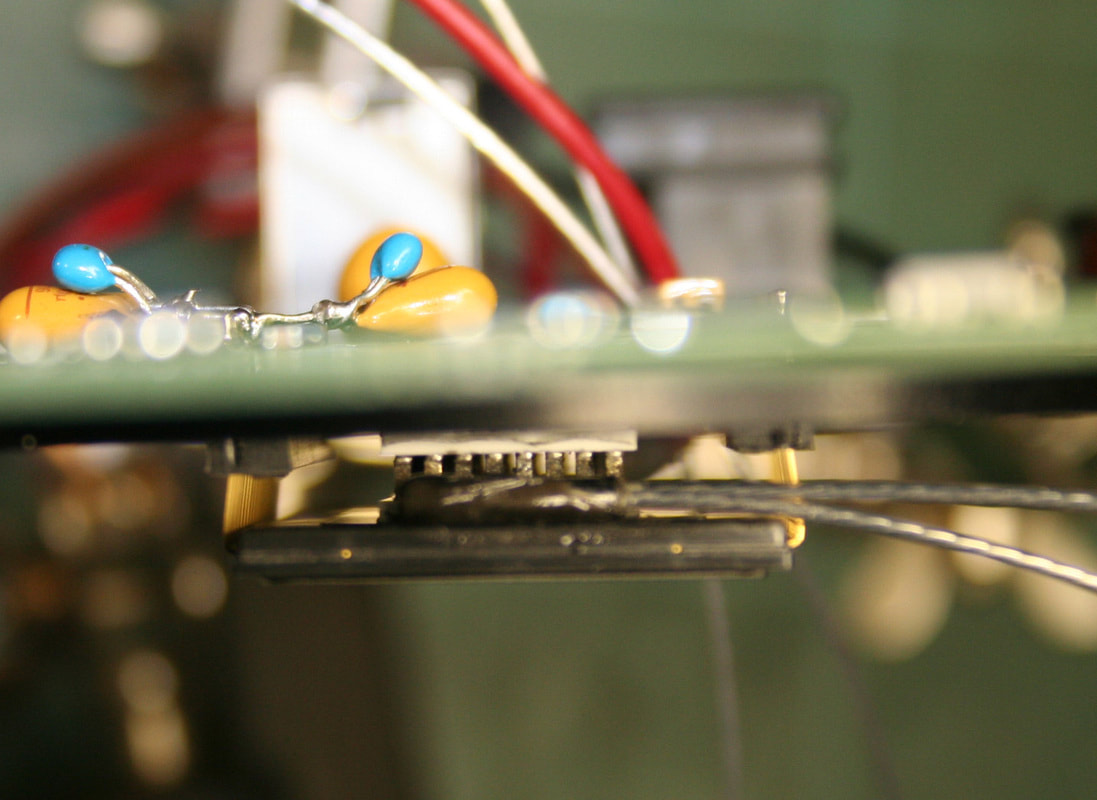
I had some ferrite beads in a parts drawer so I added beads (covered with heat shrink) to the fan and TEC wires. I figured it couldn't hurt.
I sealed the access hole in the PCB with black silicon sealant to prevent air and moisture from getting into the sensor chamber. I cleaned the IR filter and blew the dust from the chamber and CCD sensor with canned air before placing the PCB back onto the housing. |
|
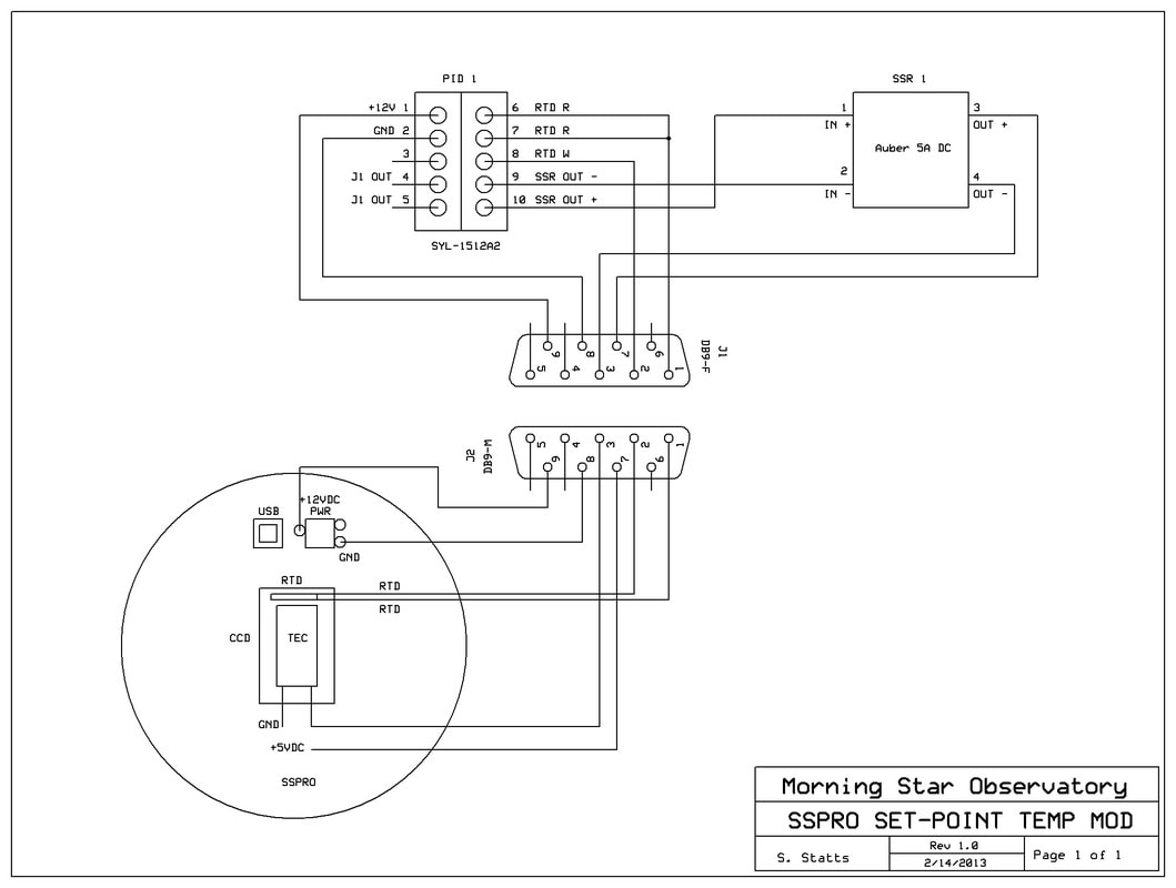
The DB-9M connector can be wired using any pins but the pinout I used is:
Pin 1 - RTD Pin 2 - RTD Pin 3 - +TEC Red wire Pin 7 - + 5VDC TEC Power Pin 8 - GND Pin 9 - +12VDC for PID Controller Pins 4, 5 and 6 - NC |
|
Schematic of the wiring modifications to the camera.
|
|
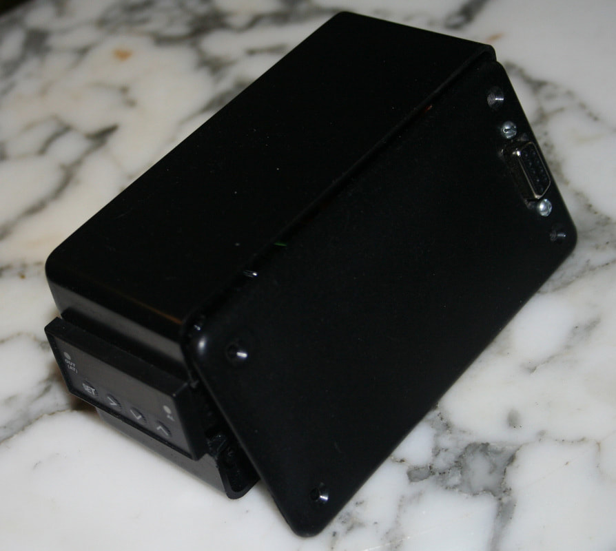
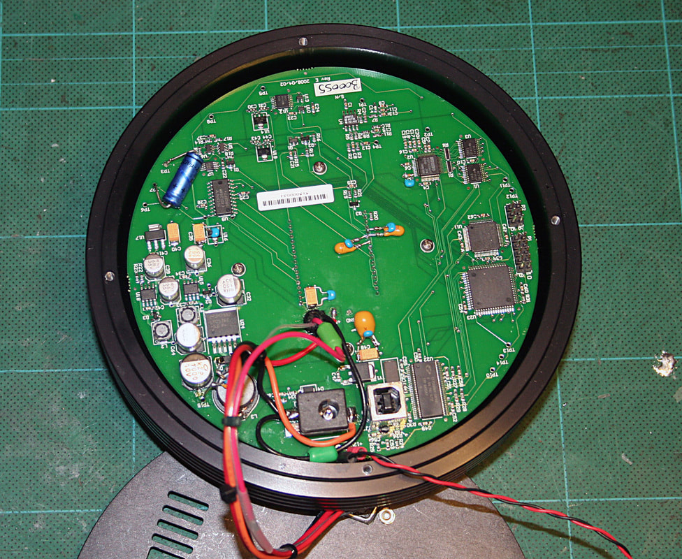
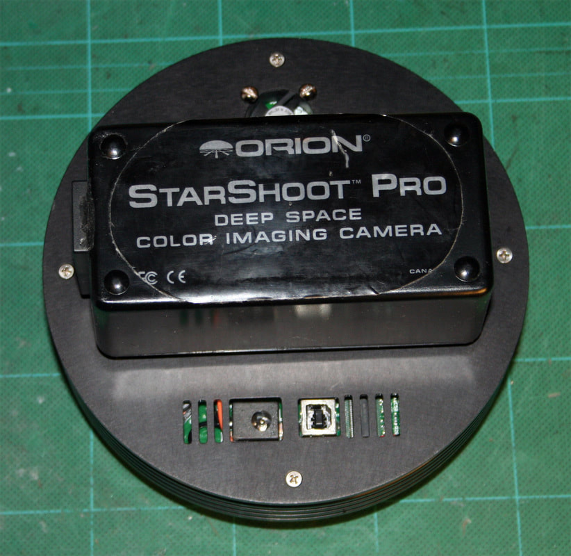
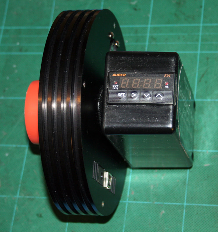
The reassembled unit. The PID controller mounts directly to the back of the SSPRO.
|
|
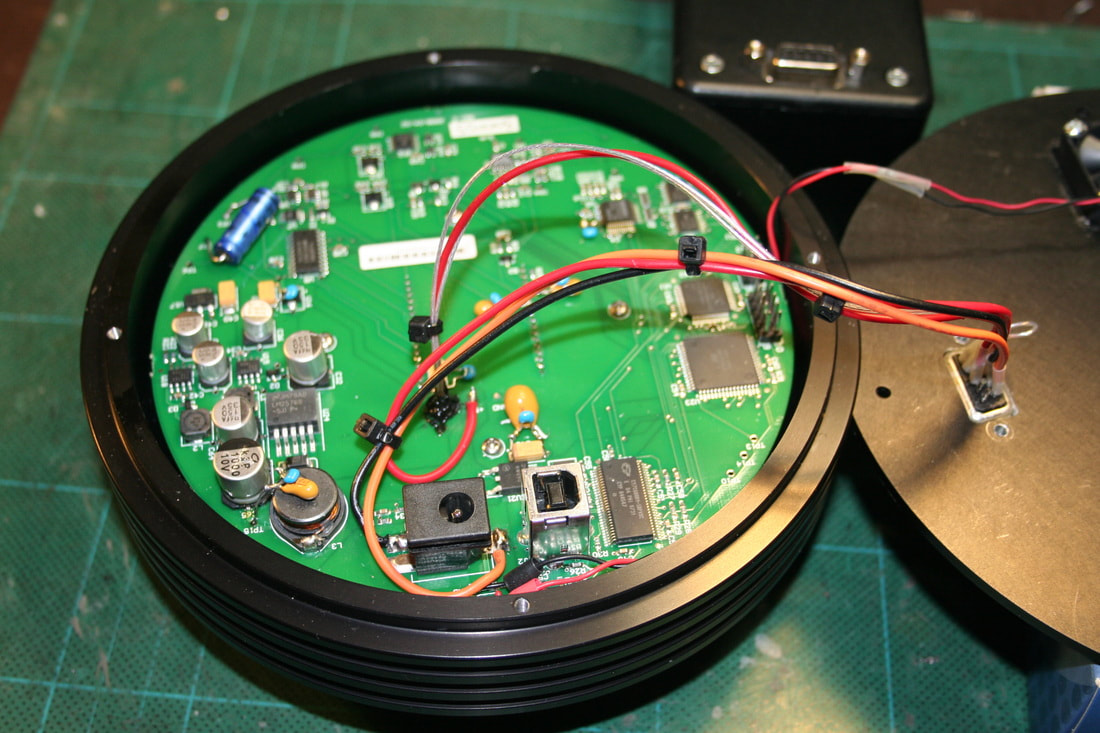
Side view of the camera and PID controller. The connector slide lock holds the right side secure and I used Velcro to attach the left side.
|
|
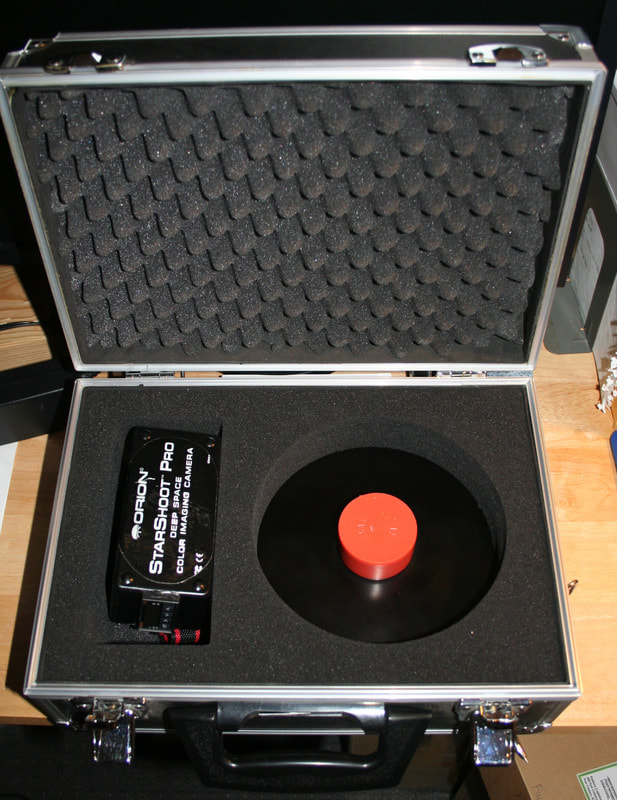
It still fits in the original case with the PID controller unplugged. And the controller drops right into the cable storage section.
|
|
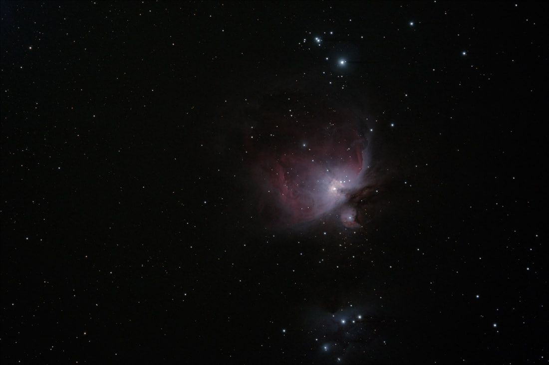
A test shot of the Orion Nebula to show the camera is working.
The air temp in the obs was in the low 40's and the camera held the temperature at the set point all night. See the Noise Reduction Mod page for more test results on the camera. |
Replacing the Damaged TEC
|
The first time I reassembled the camera and tested the cooling, I was only getting about an 8°C temperature drop on the chip. The camera's specs claim it is capable of a 30°C delta from ambient so something was wrong. I disassembled the camera again to troubleshoot and finally had to remove the CCD and TEC to discover the problem, a damaged pellet in the TEC where I had soldered the red wire. But hey, if I hadn't messed up I wouldn't have all the nifty pictures below.
This is the CCD Sensor / TEC module / cold plate assembly removed from the camera. The cold plate was super-glued to the PCB and popped loose with a little persuasion. After popping the super glue loose only the pins of the CCD held the assembly on the board. I also had to snip the TEC black GND wire. |
|
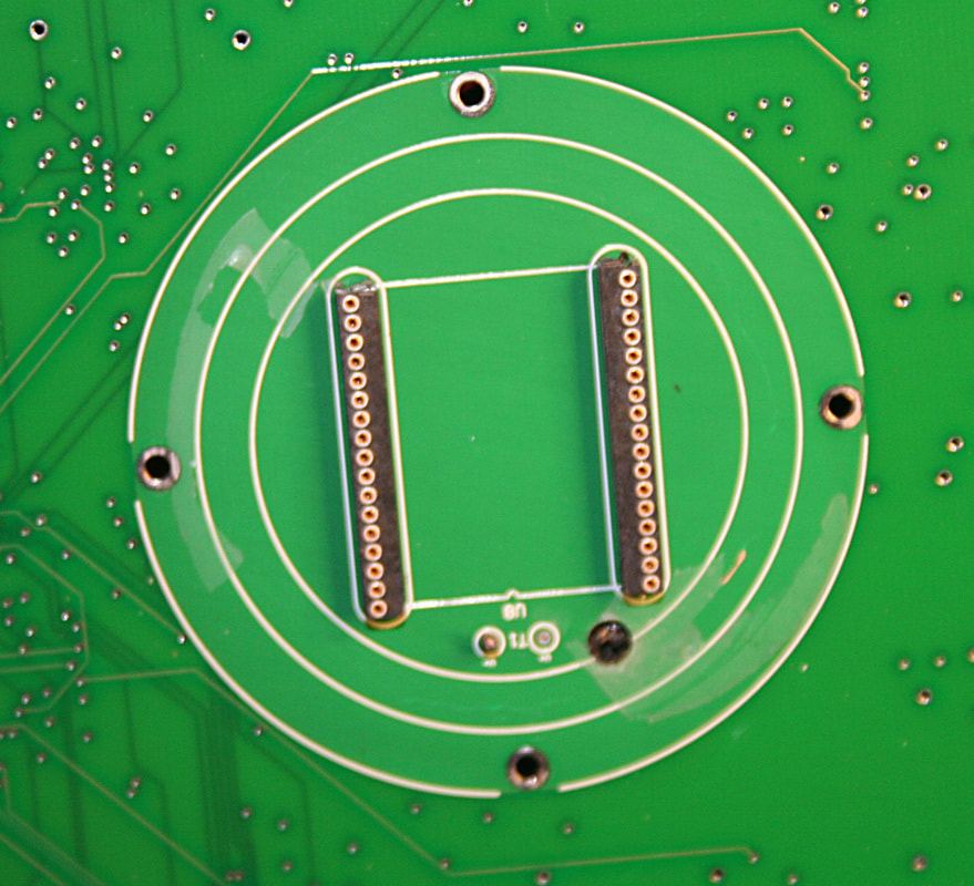
Here is the section of the PCB under the cold plate. The circle where the cold plate is mounted seems to have another circular ground plane layer in the PCB as I can see inner layer traces enter and leave the cold plate area but can't see them running within the circle. But it looks like I guessed right that there were no traces in the vicinity of where I drilled the chamber access hole.
|
|
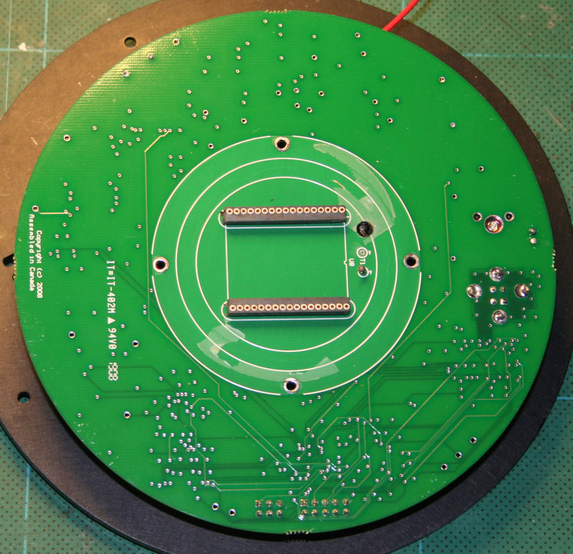
Here is the full view of the PCB with the sensor removed.
|
|
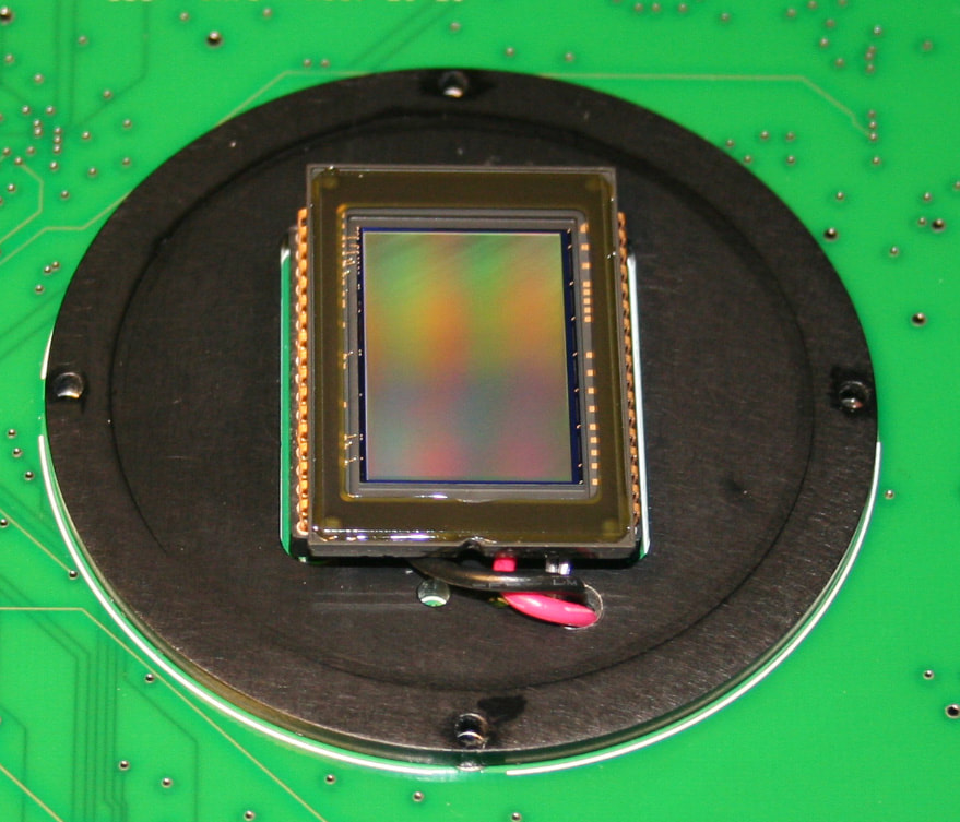
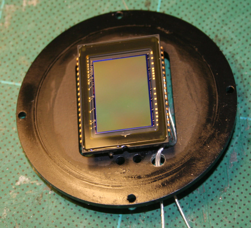
This is the back of the CCD sensor after removing the TEC. The TEC was adhered with a thermal sheet (aluminum foil with a non-silicon tacky thermal adhesive on both sides) to the CCD and to the cold plate. Some of the old thermal adhesive is still visible on the chip.
The CCD was adhered pretty well and I ended up working a sharp blade between the two to work/cut it loose. Kinda scary as I was worried about damaging the CCD, but it eventually came apart. |
|
Here's the problem. My soldering iron damaged a pellet on the TEC when replacing the red + wire - the junction got too hot. Soldering to the TEC requires low heat and special solder. I should have just snipped the red wire and spliced a longer wire onto it, instead of trying to replace the wire at the TEC. So much for trying to be neat. As Homer would say, "Doooh!"
|
|
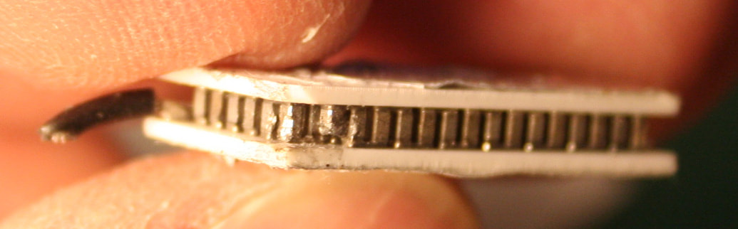
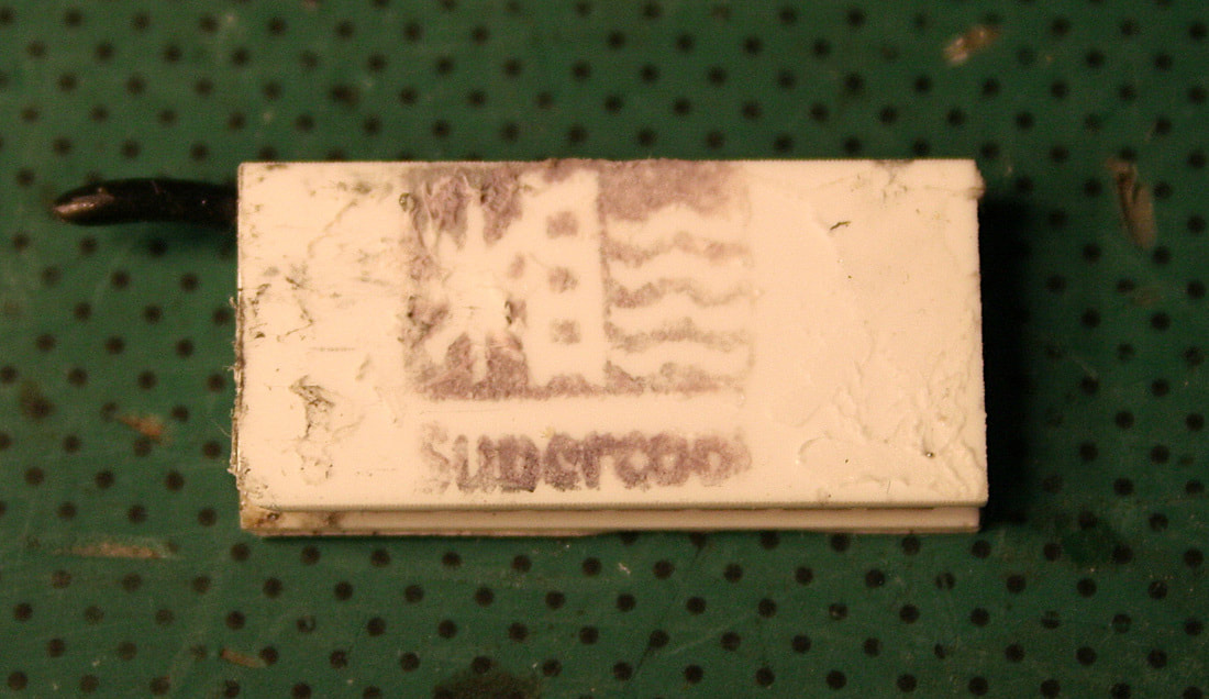
The original TEC is made by Supercool. This appears to be their model PE-063-08-15.
The specs are: Imax = 2.2 A Umax = 7.8 V Pmax = 10.4 W Delta-T = 74°C Rac = 3.20 Ohms Dimensions = 12mm W x 25mm L x 3.8mm H The red and black wires are soldered to the hot side. |
|
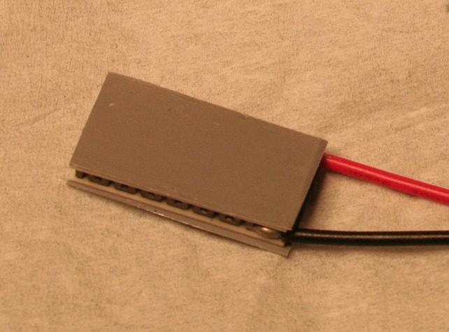
I ordered a new TEC to replace the damaged one. The replacement TEC module is from Custom Thermoelectric, part number 06311-5L31-02CDK, and is very close to the original specs. It has preconnected 6" leads. In this view the cold side is up.
I also ordered new thermal sheet material (Custom Thermoelectric part number TS-MF3A4) to adhere the TEC to the CCD and cold plate. The picture at left shows the TEC with the thermal material applied. Just need to peel off the clear covers before pressing in place. Rather than trying to resolder to the original TEC GND hole in the PCB, I ran both TEC wires out the access hole and soldered the GND at the power connector. The new TEC's specs are: Imax = 2.0 A Umax = 7.6 V Pmax = 9 W Delta-T = 67°C Tmax = 125°C Dimensions = 12.3mm W x 25mm L x 3.5mm H The red and black wires are soldered to the hot side. |
|
I adhered the TEC to the CCD sensor, set the cold plate in position on the PCB (I did not glue the cold plate back to the PCB in case I had to disassemble it again) and then pressed the CCD back into the socket, which pressed the hot side of the TEC against the cold plate.
I also had to make sure the holes in the cold plate lined up with the holes in the PCB before I pressed the CCD/TEC onto it. |
|
Testing in my warm room at about 19°C the camera held a 20°C delta for 10 minutes and then began to drift up at about 0.1°C per minute. I checked the body temp and it had risen from 18°C to 23°C. I then put the camera in the unheated obs at about 7°C and the CCD temperature quickly dropped back to the set point as the body was able to cool down again.
I returned the camera to the warm room and in about 5 minutes the body temp was back up to 23°C and the CCD temp began to drift up again. The TEC and set point are working as designed and as long as the case is able to shed the heat from the TEC, the temperature is maintained within +/- 0.1°C. I might experiment with higher CFM fans to see if that helps maintain a higher delta in warmer months. |
Last update 11/28/2017
