
Transistor Curve Tracer Kit
This curve tracer is built around the kit available from Thaikits.com. It is based on the Elektor curve tracer published in the December 1989 issue of Elektor Electronics magazine.
|
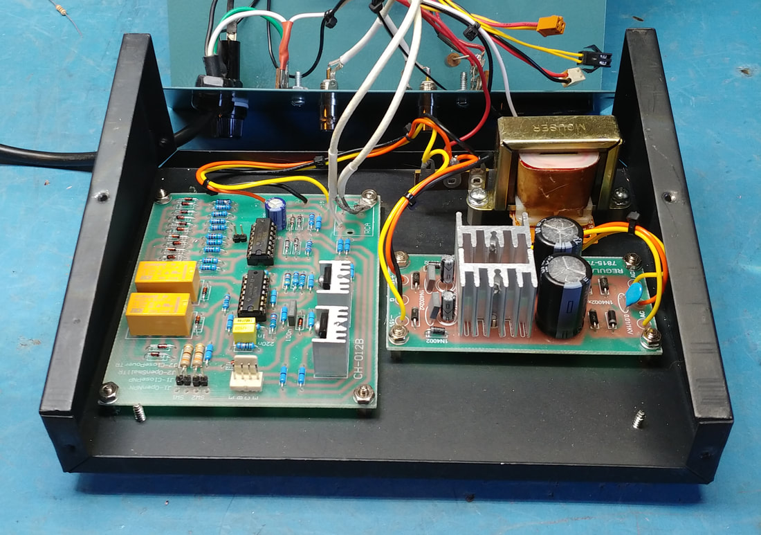
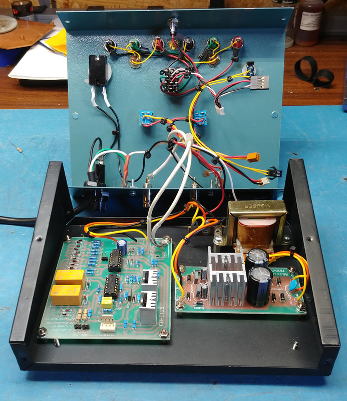
I purchased the combo tracer PCB kit and +/- 15VDC power supply kit. All the components on the PCBs are included in the kits except for the extra header pins I added for connecting the switches. All components are installed by following the silkscreen on the boards.
Not included in the kit are the case, power transformer or any of the components mounted to the front and rear panels except the two BNC jacks. |
|
I built the tracer in a vintage Radio Shack/Archer slope-front case. The case already had some holes drilled in it so I had to plan my panel layout to accommodate them.
|
|
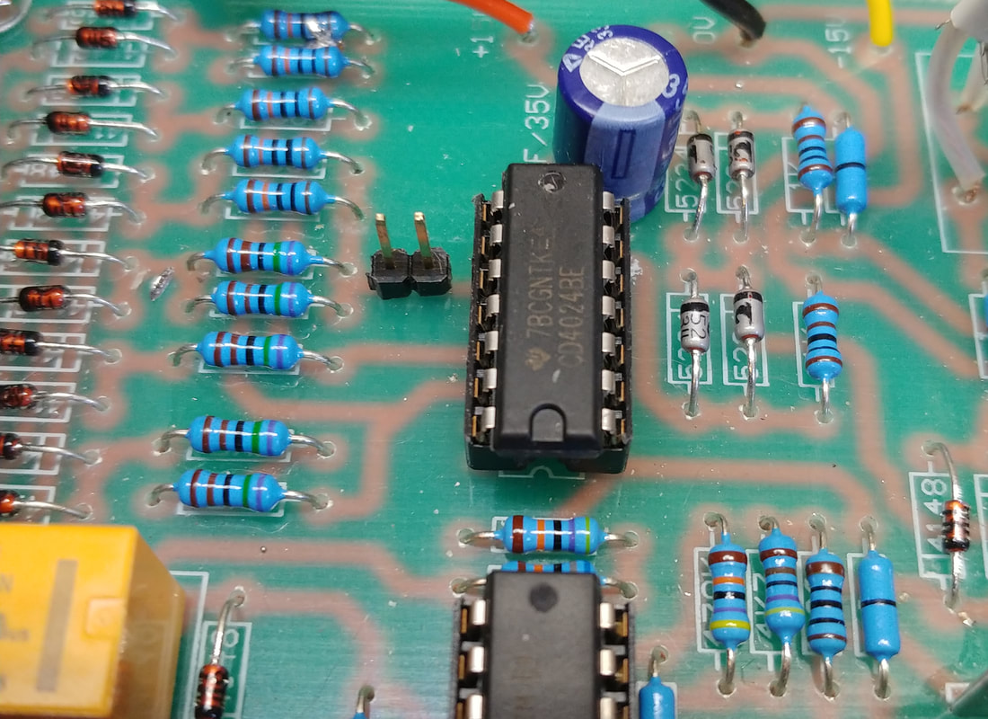
I made only one modification to the tracer PCB. The original Elektor version had a switch inline between pin 9 of the 4024 counter IC and the D/A resistors, to switch between 4 or 8 curves on screen. I cut the trace to pin 9, drilled holes in the trace on each side of the cut, and added a two-pin header for connecting a front panel switch.
|
|
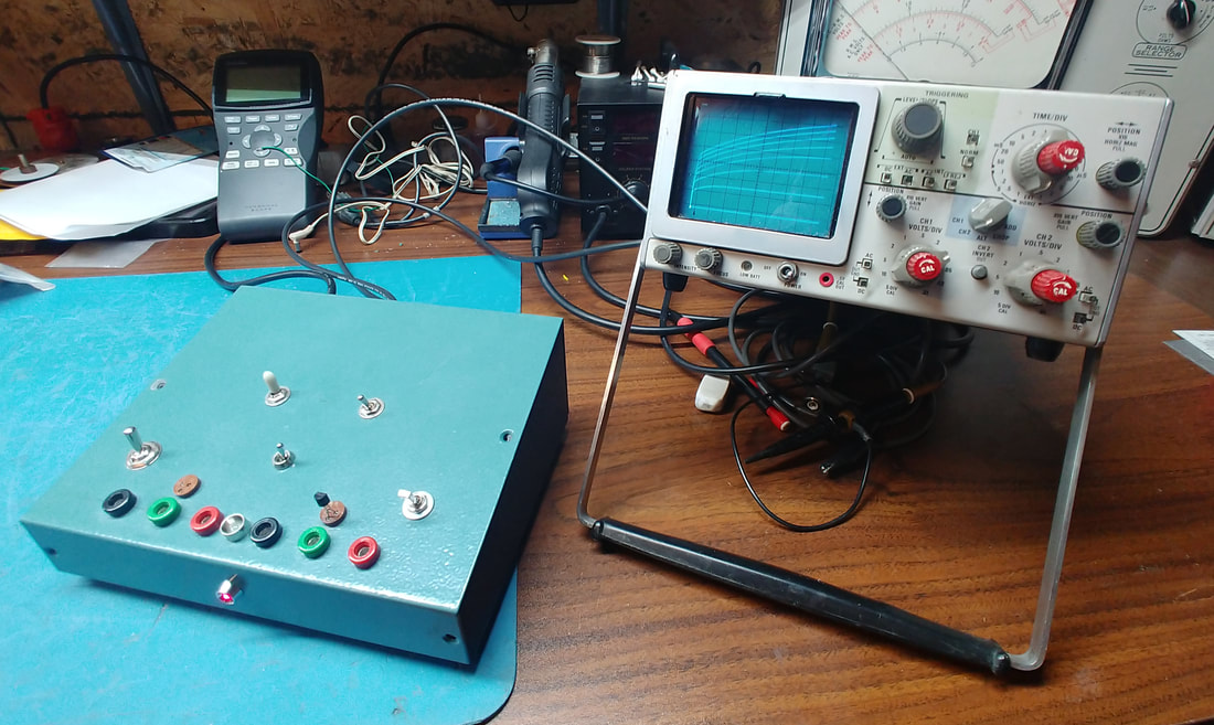
Testing the tracer using my Tektronix 326 scope. The 326 doesn't have a built-in X/Y mode, but it does have an external horizontal input. The X and Y BNC jacks are on the rear of the tracer. On the 326 X goes to EXT HOR input and I connect Y to one of the vertical channels.
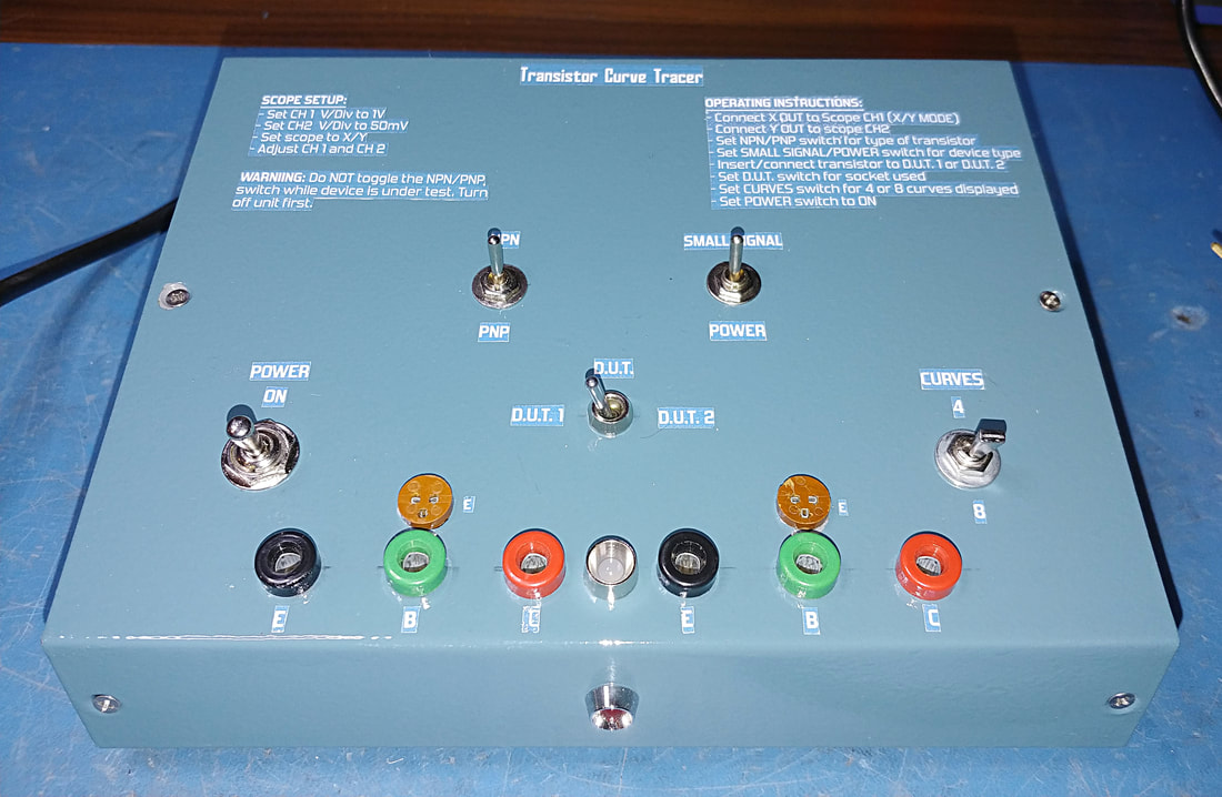
I installed two sets of test sockets in the tracer that connect to the PCB through a 3PDT switch. The sockets and banana jacks are mounted fairly close together to keep lead lengths as short as possible (to prevent oscillations). The original Elektor article recommends less than 10cm which is hard to do when mounting the PCB in a case. These leads are longer than 10cm so I added ferrite beads to the socket wiring to help prevent oscillations. With the two sets of sockets I can compare curves and match transistors with the flip of a switch. |
|
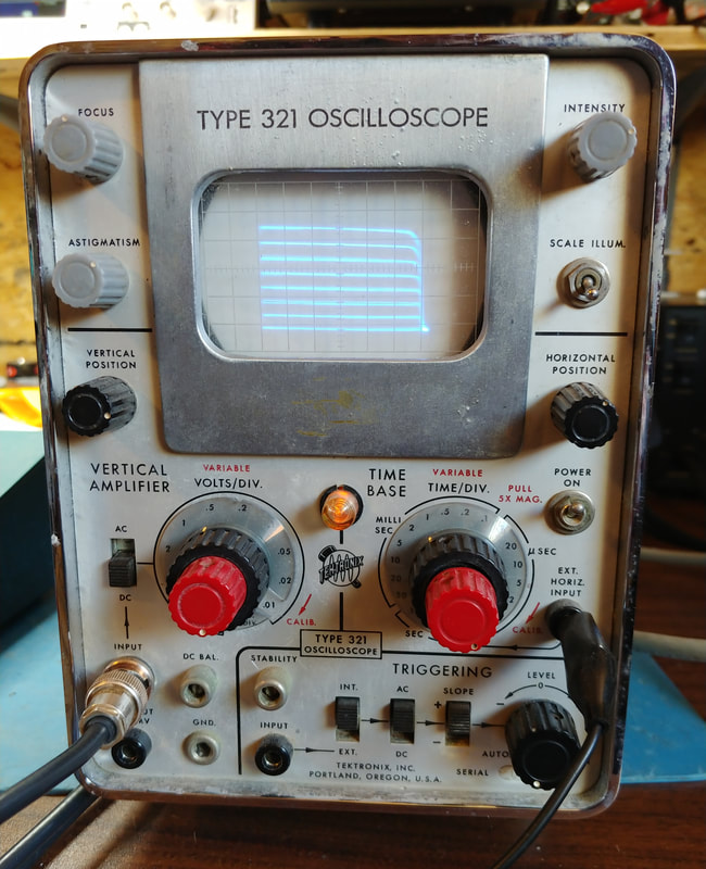
Just for fun I hooked the tracer up to my old Tektronix 321. The display doesn't look too bad, needs a bit more horizontal gain and the curves are reversed horizontally.
|
|
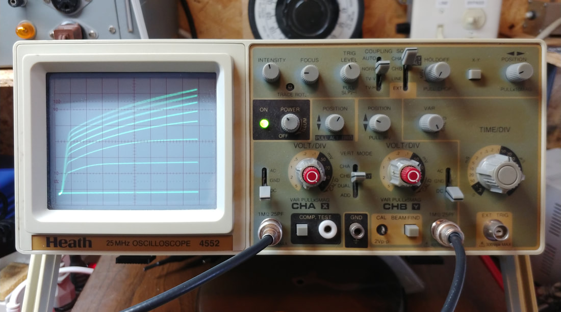
My Heathkit scope has an X/Y mode and displayed the power transistor curves well enough, but the small signal curves were quite noisy. I went through the tracer with a scope checking waveforms and looking at ripple and noise on the +/- 15V rails, but it wasn't until I started checking grounds that I discovered the problem. I had grounded the X and Y coax cable shields to a lug attached to a metal standoff for the PCB. But the power supply and tracer PCB are grounded to the chassis at a terminal strip near the power transformer. Since a single point ground is usually a good idea for lower frequency stuff, I pulled the coax shields from the standoff solder lug and grounded them at the power supply ground. And magically the noise completely disappeared. I'm now very happy with the curve tracer's performance.
|
|
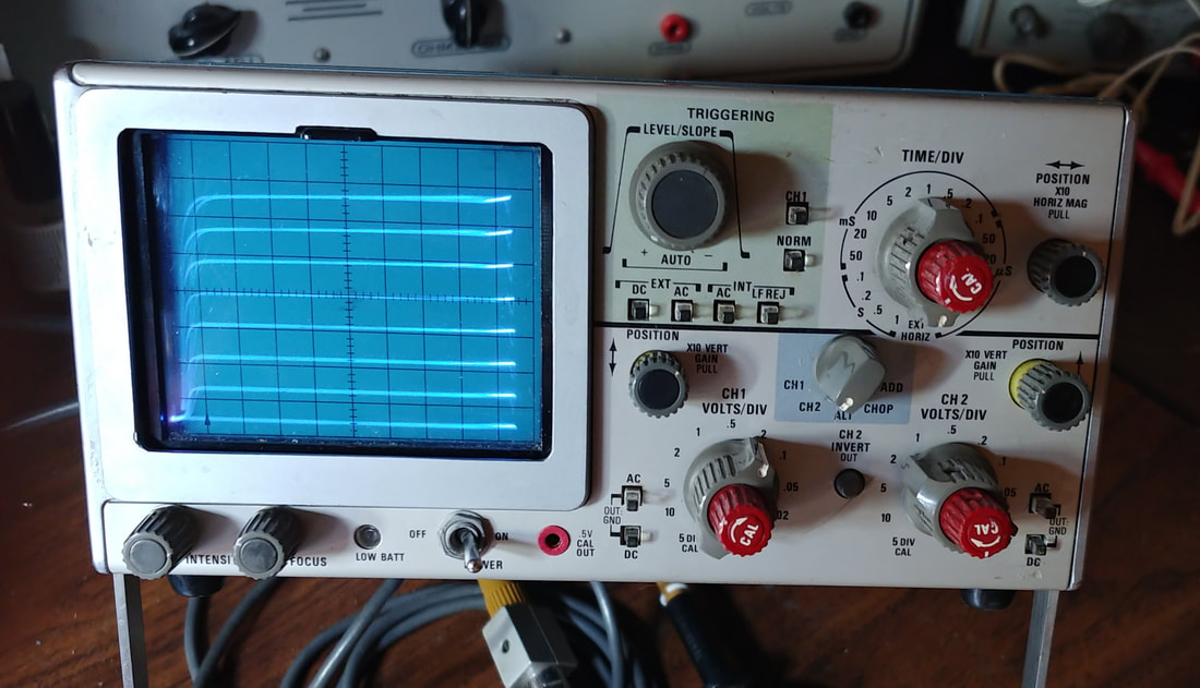
These are curves for a BC548. The tracer is in small signal mode and I have the scope's vertical channel 10X magnification on. Before moving the grounds to a single point, using the 10X magnification overwhelmed the display with noise making it unreadable. Now it's clean and easy to read.
|
|
The tracer completed. This should fit my needs nicely. I don't need to match or test transistors every day, but when the need arises this little curve tracer is likely all I'll need. It's no Tektronix unit but I can't really justify the cost of something like a Tektronix 575 for the amount of use it would get.
|
Page Created 2/29/2020
Last Edited 3/26/2020
Last Edited 3/26/2020
