
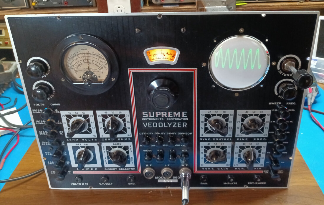
Restoring a Supreme Model 560 Vedolyzer
The model 560 was the short-lived first version of the Vedolyzer. Introduced in magazine ads in 1939, the 560 would only be around for about a year before being replaced with the updated model 560-A. The 560 was listed in the 1940 Supreme catalog, which stated it had been in development for two years.
Supreme ads announcing the new model 560 Vedolyzer appeared as early as June 1939, and in the September '39 edition of Service Magazine Supreme announced that the new 560 Vedolyzer, 561 AF-RF Metered Generator, and 562 Audolyzer were all ready for delivery and that more than 100 orders had been placed for the new models even before prices were announced. But it doesn't say how many of those were Vedolyzers. This 560 is serial number 103 and is the only one I've found in a modern day photograph online, so I'm doubting there are many of the original production still around after 80+ years.
In comparison, my 560-A is serial number 101 and judging from "A" serial numbers and photos I found online, at least four or five hundred of the "A" version were produced before production ended, which I think was sometime around 1942. More info about the Vedolyzer is available over on my 560-A restoration page.
|
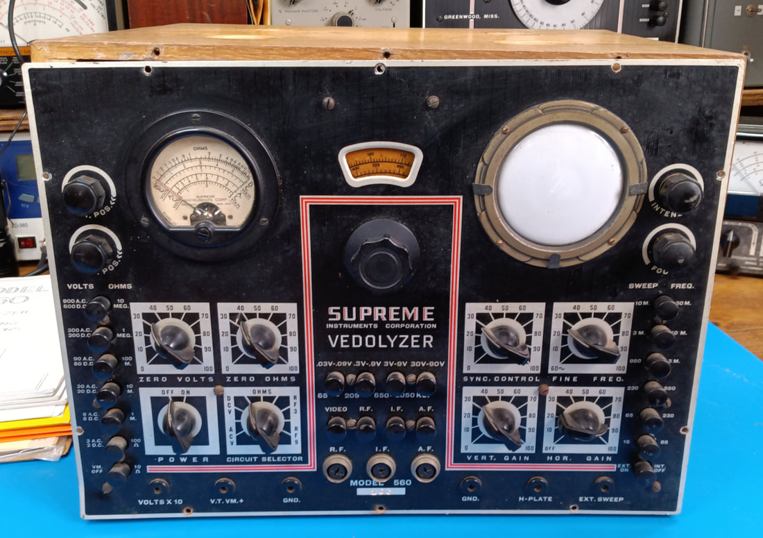
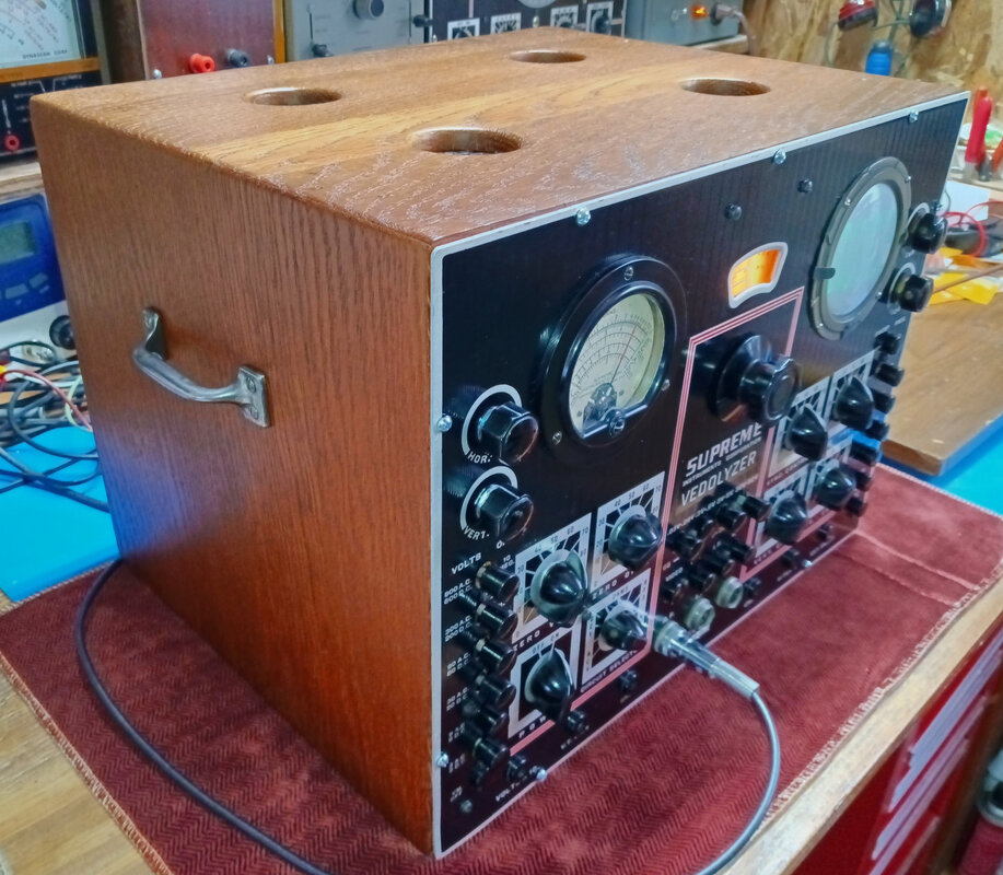
This Vedolyzer came to me through an online seller from a long time radio collector on Long Island, NY, but that's about as much as I know about it. My guess is it likely came out of a radio repair shop around New York City. It's front panel is not in bad shape and all the knobs are there. And there aren't any really nasty scratches or paint loss.
|
|
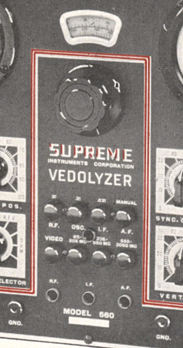
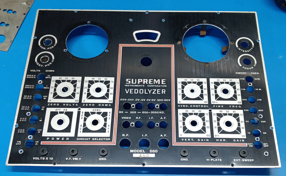
There are a number of differences not only between the 560 and 560-A, but also between the photo of the 560 in the 1939 and 1940 ads and this model 560. Some labels and even the input connectors are not the same. The function and wavemeter labeling, as well as the Circuit Selector labels and Volts X 10 label are all different in the photo.
And there is what looks like a connector right in the middle of the multiplier and function buttons, although I don't think it's really a connector, but possibly an access hole to adjust a trimmer for the wavemeter input that's located on the function switches. My 560 doesn't have this hole and the trimmer is mounted vertically behind the switch assembly. I wish I could find an original 560 manual for this, it would probably explain a lot. I think it's unlikely my 560 would predate the photo, since the ads and catalog page for the new instrument would need to be created ahead of its release, and the first ads with the photo were as far back as June of '39. And the catalog this picture was scanned from has "SIC 2139" near the bottom of the last page, which I suspect is the catalog number, with 39 indicating the year it was printed. So the model 560 in the photo may well be a pre-production unit. It doesn't even have a serial number stamped on it. Either that or Supreme made a whole lot of changes really quickly after it's release. |
|
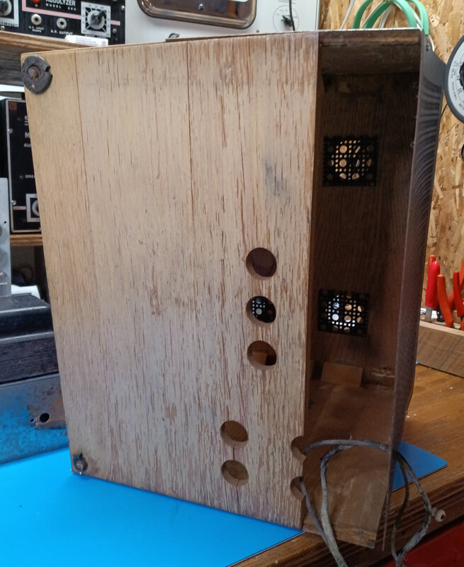
The cabinet is not in such good shape, and is separating at its seams, plus one piece is completely missing from the bottom.
In the 1939 ad, there is a leather handle on top of the 560, but this one has metal handles on the sides just like my model 560-A (the same is true for the 561 and 562). And in the ad photo it also does not have the vent holes in the top like this one and my 560-A. Supreme was known for continually making changes during production, so the cabinet differences might be early changes, or more likely, the cabinet in the picture is also pre-production. |
|
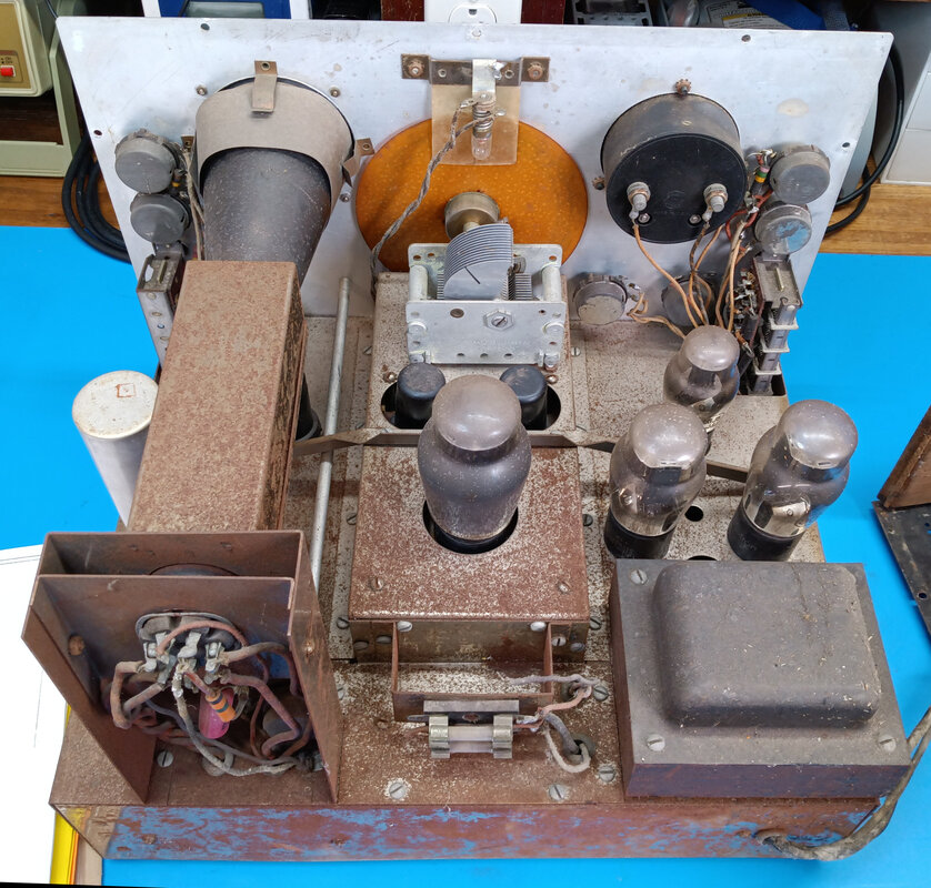
The top of the chrome chassis is covered with rust. Not sure yet what I'm going to do with the it, but the first step is to just clean it up. Then, if the chrome looks too bad, I might paint the chassis in a black wrinkle finish. A couple of my other Supreme instruments have chrome chassis that Supreme painted over with black wrinkle paint at the factory.
|
|
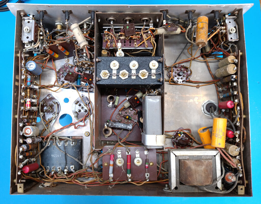
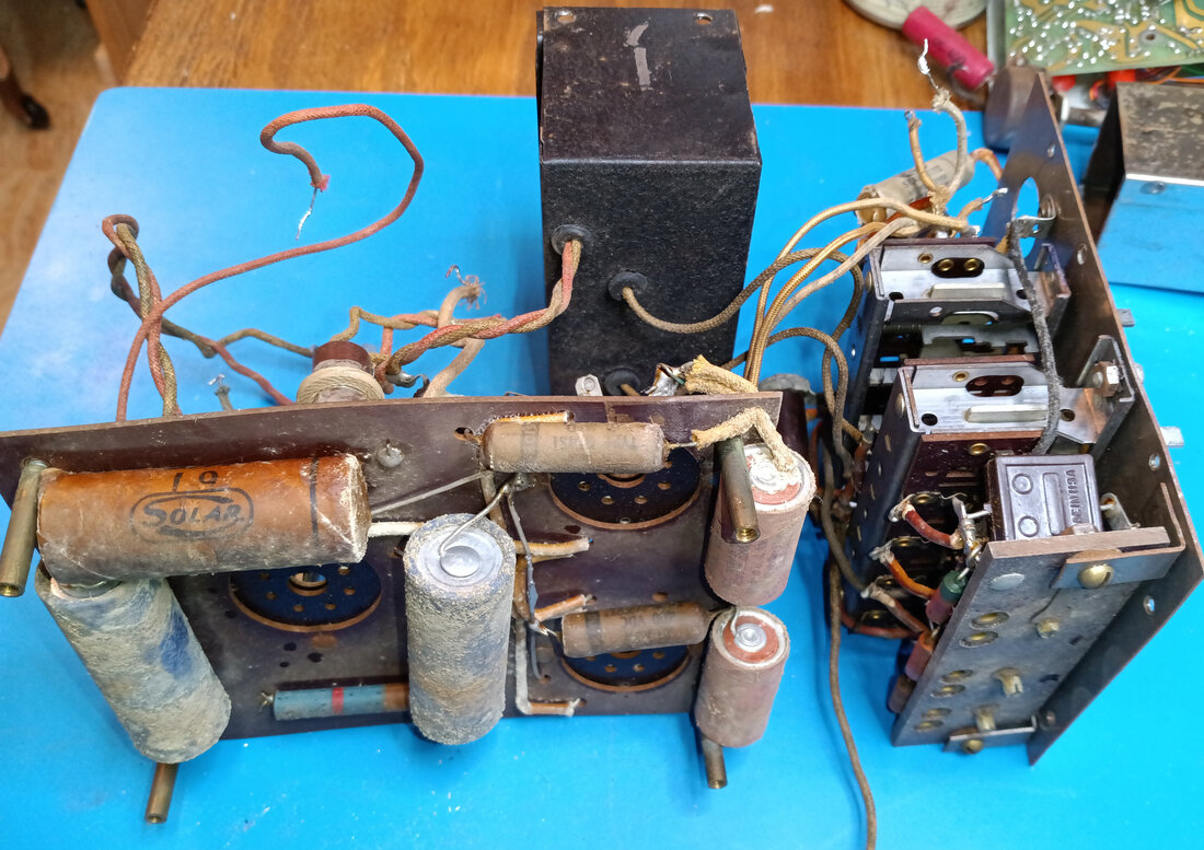
There's not much rust under the chassis, thankfully. The video amp and wavemeter are integrated into a single sub chassis in this version which should make it easier to remove them. I see about half-a-dozen wires that need disconnected first though.
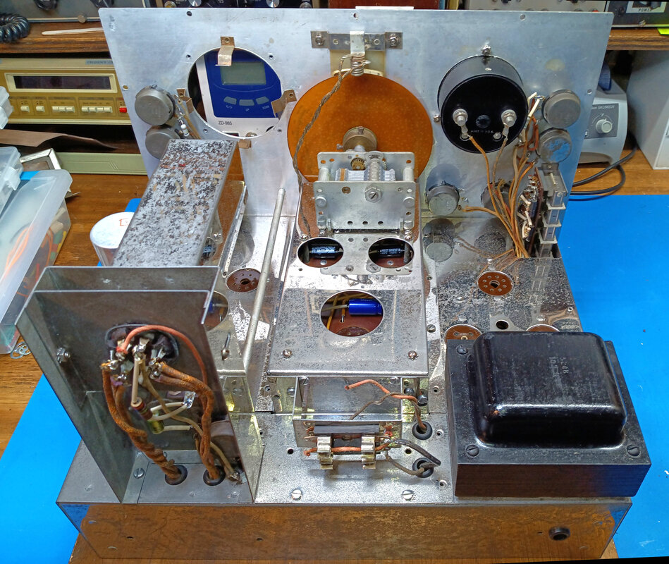
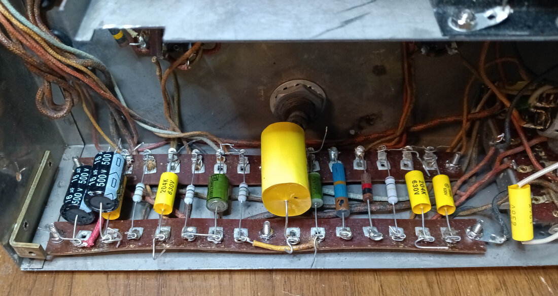
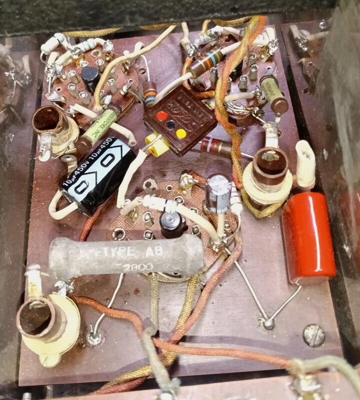
It's been worked on in the past and some of the waxed paper and foil capacitors, as well as the power supply electrolytic filters, have been replaced. Judging from my other Supreme equipment, the factory used Mallory, Solar and Cornell-Dubilier capacitors, so any other brands are likely not original. |
There's one Aerovox wax cap that doesn't look original, and the red plastic encapsulated capacitors are Sangamo Type 30 caps, which were first introduced in 1946, so they are replacements too, as is the gray Sangamo 2uF 600VDC capacitor in the middle of the chassis. The two yellow Sprague Atom-lytic 16uF filter capacitors are not original either, and have date codes of 1966 and 1969, plus there's an extra C-D 8uF filter cap that was added and which also has a 1969 date code. But the rest appear to be factory parts.
|
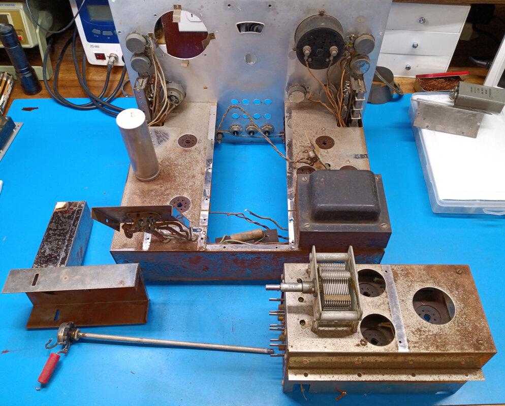
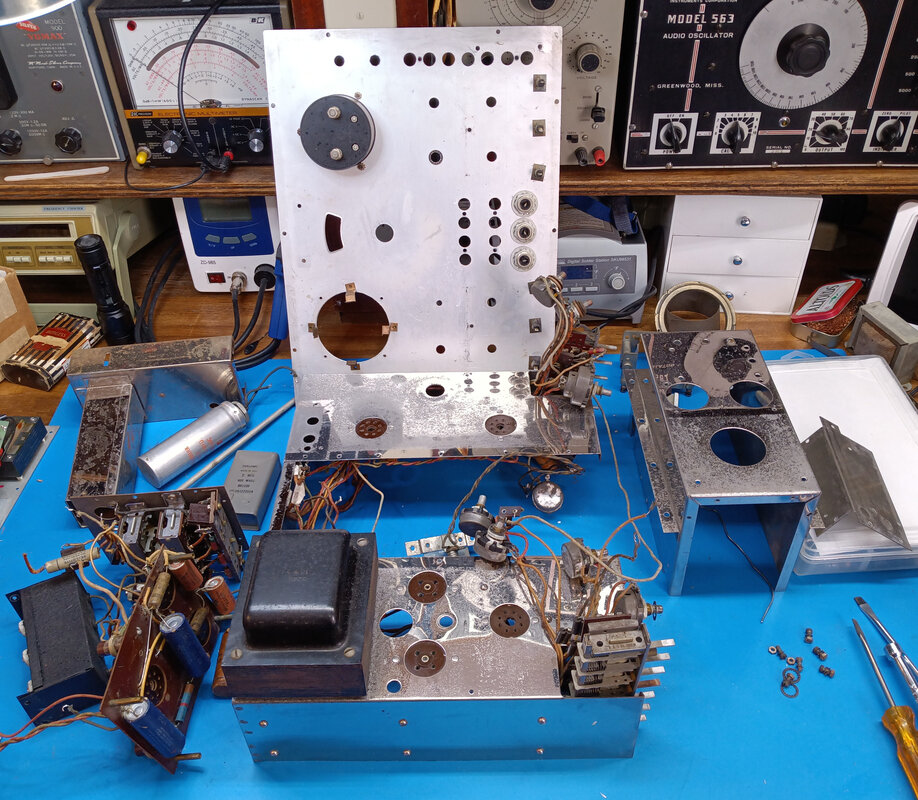
Starting to disassemble the chassis to begin cleaning and rebuilding the video amp and wavemeter subchassis. I will also have to remove the front panel to get at the two pushbutton switch banks on either side.
The most important thing to do before and during disassembly is taking photos, lots of photos, and from every angle possible. Since I only work on restorations in my spare time, it may take weeks or even months to finish a project, so I'm constantly referring to photos of the equipment to remember how it all goes back together. |
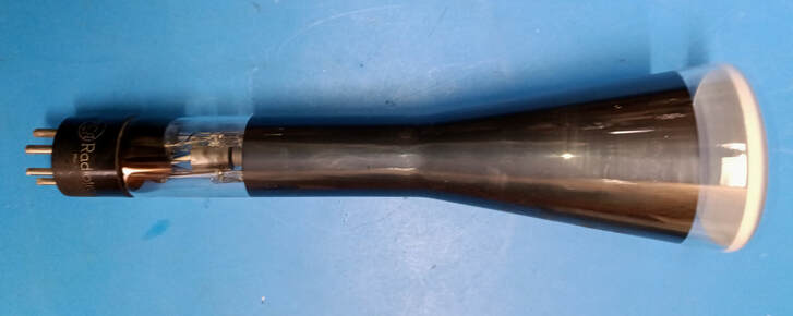
It still has a 906 CRT installed, so this may be the original tube. It looks OK, but I wont know for sure until the Vedolyzer is powered up. If it's bad I'll have to substitute a 3AP1, which is basically an updated 906.
|
The video amp and wavemeter subchassis is 5-inches deep, which should make it fun to rebuild. This subchassis is very different from the one in the 560-A.
I pulled the Sangamo 2uF capacitor to test and it failed at a couple hundred volts, so it will be replaced. And since I already had the Heathkit IT-28 powered up for cap testing, I pulled the 0.5uF 1500VDC capacitor from the CRT high voltage supply and checked it. It didn't make it past 50-volts on the tester, so I'll need to order a new one of those, too. There's really no need to test any of the other paper caps since there's not a one under 50 years old, and most are over 80, so they will all get replaced. The mica caps will be tested though. |
|
Everything inside the subchassis has been pulled out to rebuild the video amp and wavemeter. The two 1852 video amplifier tube sockets and the 6L6 vertical output tube socket are mounted on a phenolic board with the amplifier components on both sides. The black metal box contains the wavemeter coils and trimmer capacitors. The input selector and wavemeter selector buttons are mounted to the subchassis end plate.
|
|
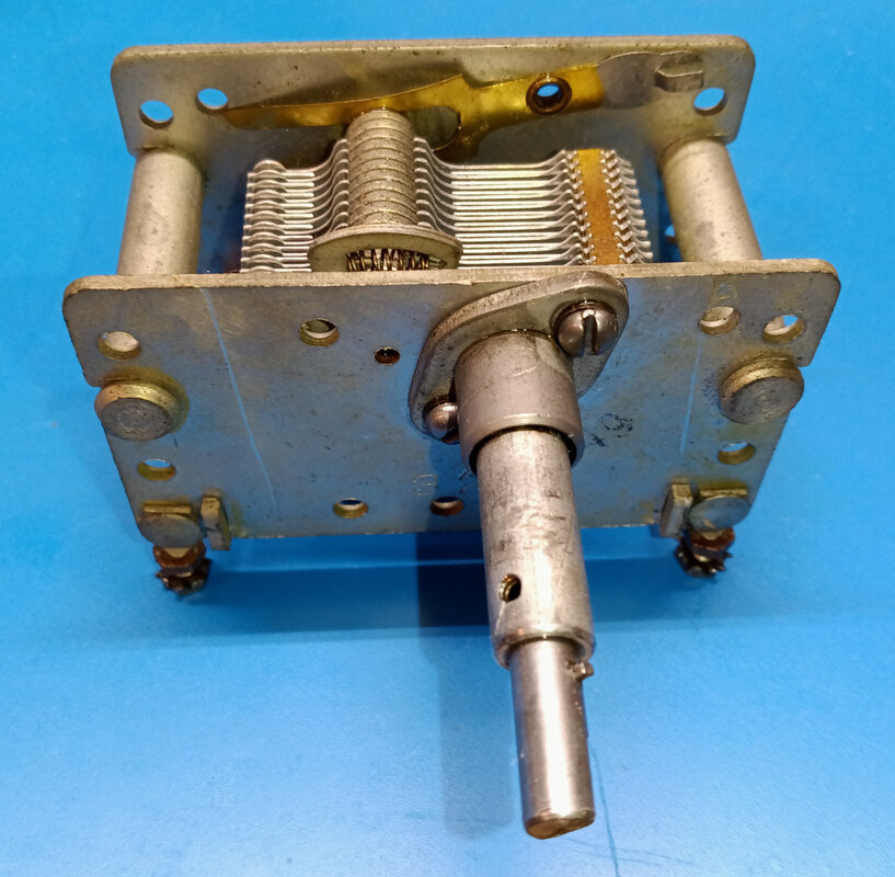
I also pulled the wavemeter variable capacitor to clean and lube it because the 5:1 gear reduction was so completely gummed up the knob shaft just spun around without moving the capacitor rotor at all. A good soaking in WD-40 and then relubing it with spray grease has it working again.
One difference between the 560 and 560-A is the frequency range of the wavemeter. The range of the 560 is 65KC to 2.05MC, but the 560-A has an additional band extending the range from 2.05MC to 6.5MC. |
|
All disassembled and mostly derusted. The rust is being removed using a liquid rust remover, one section at a time. After that's flushed off it gets rubbed down with aluminium foil and then chrome polish is applied. After polishing a carnauba paste wax is applied because of all the exposed steel in the pitting. Hopefully that will seal it up and prevent any new rusting. The chrome is still not in great condition, but it looks much better than the rusty mess it was before.
|
|
The front panel has been cleaned and waxed. A couple of small scratches were touched up and the bent corner was straightened some. Couldn't quite remove all the bend because I didn't want to chance damaging the paint.
I'm leaving the original tip jacks and input connectors installed to keep it looking original. I will also clean and reblue the fillister head screws that are used on the front panel. The front can go back on the chassis as soon as I finish rebuilding the left and right switch banks. |
|
|
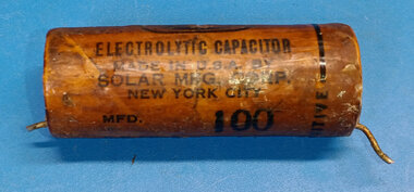
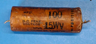
Here's a little twist on wax capacitors. At first glance it would just appear to be another paper and foil wax capacitor, but it's actually an electrolytic. And the black stripe identifies the positive end, not the outside foil or ground end.
|
|
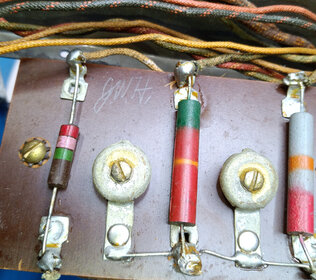
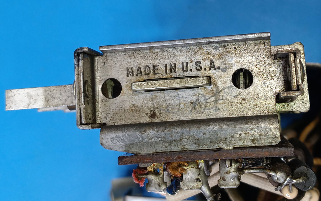
So far I've found two signatures of people who helped build this Vedolyzer. One initialed it on one of the small phenolic boards under the chassis, and the other initialed the top of the voltmeter pushbutton frame.
|
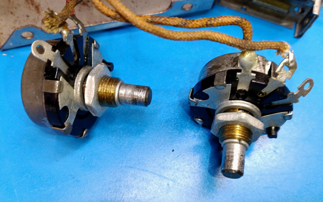
While I'm waiting on a parts order of capacitors and resistors to arrive, there's lots of little stuff I can fix. For example, both the Zero Volts and Zero Ohms control shafts were seized tight. But using WD-40, both shafts were eventually freed up. Then the controls were cleaned with Deoxit.
|
|
|
|
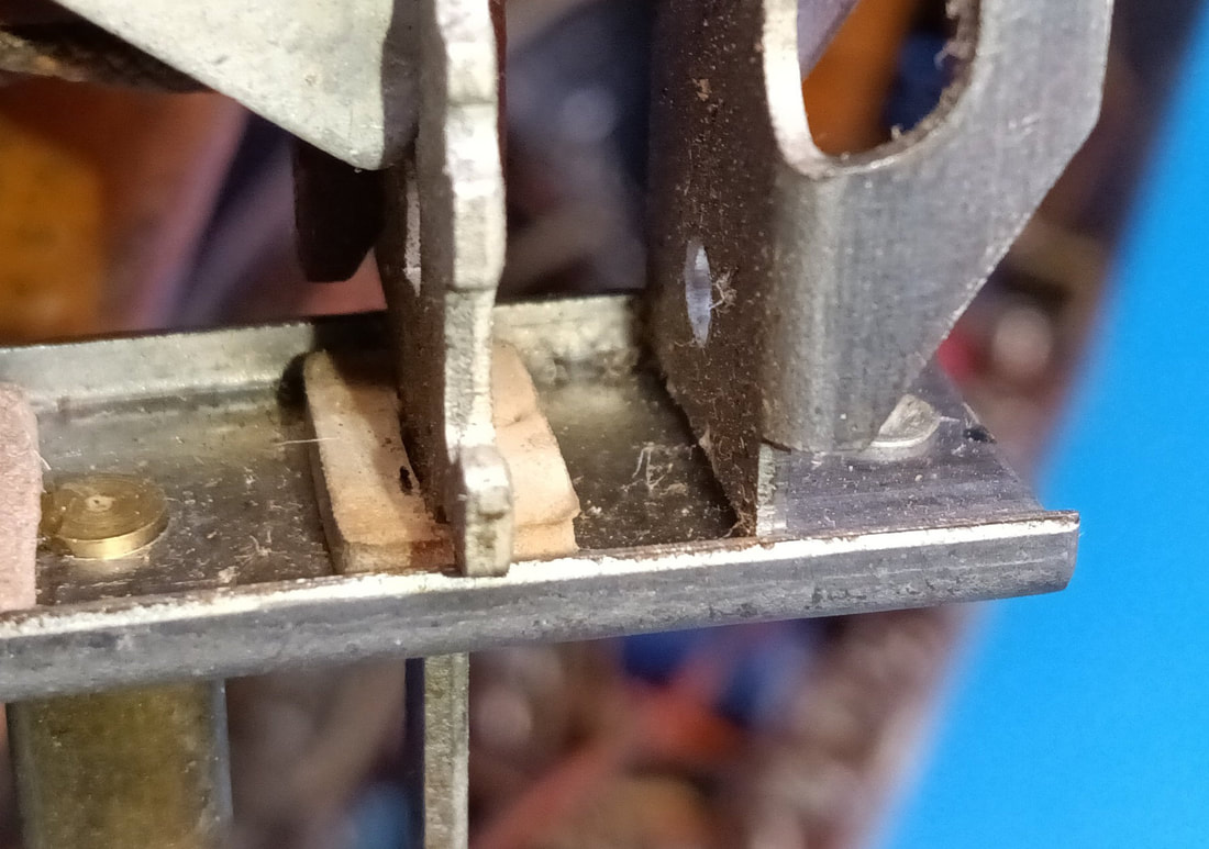
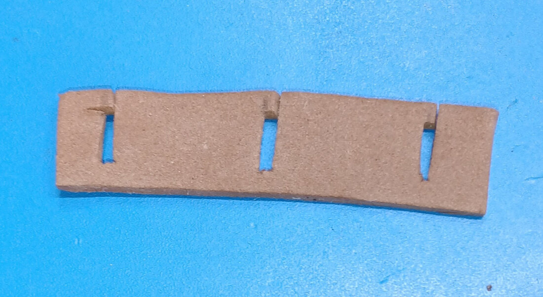
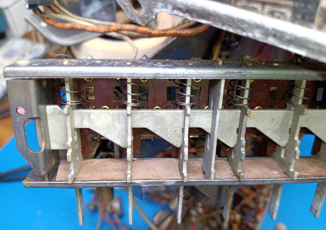
More little stuff, replacing the rubber bumpers on the pushbutton switches. Instead of making individual bumpers I cut a rubber strip to glue inside the front of the switch frame. In the first photo is one of the original bumpers. In the second photo is the strip I made from a foam sheet. In the third pic the new strip has been fitted around the switch shafts and glued to the inside of the front frame.
|
|
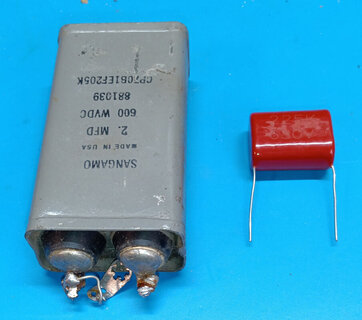
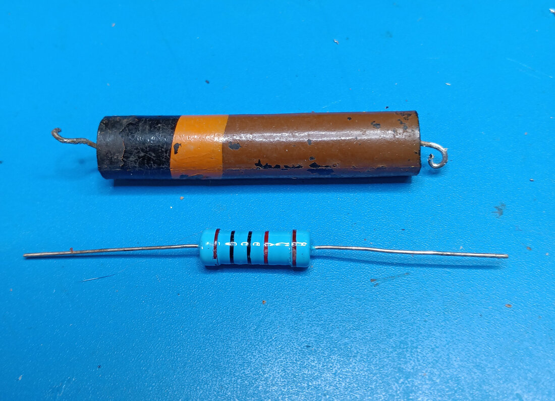
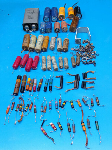
Sometimes there's quite a difference in size between old parts and new. The new 2uF replacement film capacitor is a fraction of the size of the non-original one removed from the 560, as is the new 3-watt metal film resistor compared to the 80 year old carbon power resistor it's replacing.
The smaller size of the 2uF capacitor allowed for installing it on the phenolic board, instead of the video amp side wall where the big cap was mounted.
But at other times the small size of the replacement can be a problem when the tie points for the original component are far apart.
The smaller size of the 2uF capacitor allowed for installing it on the phenolic board, instead of the video amp side wall where the big cap was mounted.
But at other times the small size of the replacement can be a problem when the tie points for the original component are far apart.
|
The parts order finally showed up so now the pushbutton switches are finished and the front panel has been reinstalled. The video amp is also finished and back in place.
Three capacitors on the sweep speed switches were replaced plus five precision resistors on the voltmeter ranges. I paralled another resistor on several other range resistors to trim their combined resistance back into tolerance. The chrome is very spotted from all the pitting, but it cleaned up much better than I was expecting, so I'm not going to paint it. I will wax it one more time though, before it goes back in its cabinet. |
|
The rebuilt video amp and wavemeter. A total of 7 electrolytic and 5 waxed paper capacitors were replaced, plus 10 resistors.
|
|
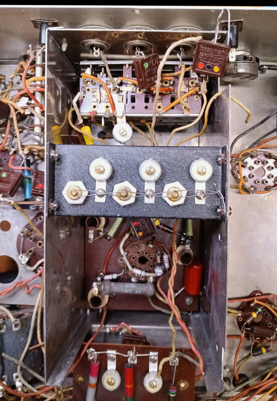
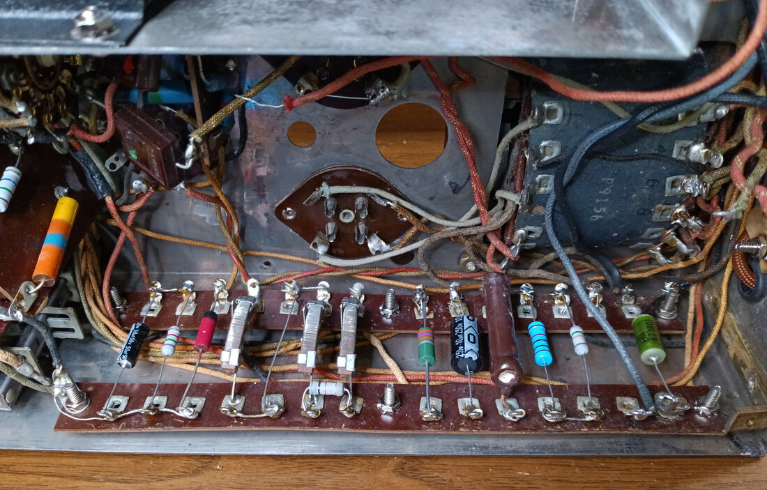
In this photo I'm going through all the parts on the right sidewall terminal strips, replacing bad and out-of-tolerance components. The new parts have been fitted but no leads trimmed or soldered yet. Before soldering I'm identifying each part on the schematic and tracing the wiring to confirm all connections are correct.
I also made the same mod I did in the 560-A in order to the mount the filter caps directly to the terminals boards. |
|
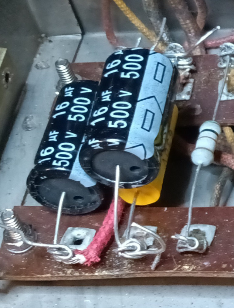
The change for the filter capacitors is very simple. Counting the terminals rows starting with one on the left, I removed the jumper connecting the top terminal of row one to the top terminal of row two, and connected a new jumper from the bottom terminal of row two to the top terminal of row one (the red wire). Then the first 16uF capacitor is wired to the upper and lower row one terminals (+ to upper terminal). Next the positive end of the second 16uF cap is wired to row two's top terminal, while its negative lead is also wired to the lower row one terminal along with the first 16uF capacitor's negative lead.
The choke gets wired to the upper terminals of rows one and two. This change cleans up the crowded corner and also makes connecting the choke easier. In the 560 there is also a 0.1uF capacitor wired from the upper to lower number two terminals. This capacitor is not in the 560-A. |
|
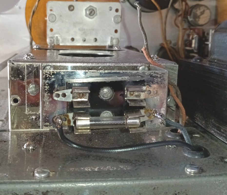
The left sidewall terminal strips are done, and the components identified and the wiring traced to confirm everything is correct. A small mod to the AC wiring on the right end of the terminal strips has been made to make it match the schematic.
As the AC input was originally wired, one side had the fuse and the other side the power switch. But they should be in series on the line side, and that's how the schematic is drawn. Back in the day it really didn't matter if the switch and fuse were in series, because they didn't use polarized plugs anyway. |
|
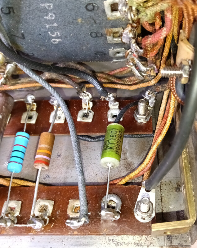
To correct the AC wiring I need to free up a terminal lug for the neutral connection, so on the first pair of terminals on the right side, the ground lead of the .047uF capacitor that was attached to row one's lower terminal is now grounded directly to the lug on the terminal strip mounting screw. This frees up the bottom terminal lug of row one for connecting the AC cord neutral wire to one side of the power transformer primary.
The second pair of terminal lugs from the right side are the connection points for the power switch, and the other side of the transformer primary has been soldered to the bottom terminal. Then a wire was added from the top terminal up to the AC fuse block. |
|
The line (hot) side of the AC power cord is connected to one side of the fuse, and the black wire coming from the power switch terminal under the chassis is connected to the other side.
Now with the addition of a polarized power plug, the fuse and power switch are both in the line side of the incoming AC as they should be. |
|
The 560 is almost ready to be powered up and so far the parts replaced include 40 resistors, 18 paper and foil capacitors, and 11 electrolytic caps (including the non-original 2uF can which was originally an electrolytic). I also replaced the rusty old 6-32 nuts and star washers, panel nuts and washers, and any screws that didn't clean up. The tubes were checked and the 6L6 has an intermittent short between pins 4 and 5 or 4 and 8, so it will be replaced.
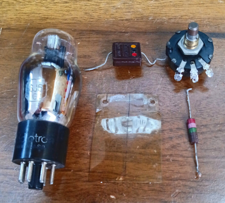
Other items used include 4 new rubber feet for the cabinet, a new cloth-covered power cord with a polarized plug, a couple of feet of vintage style spaghetti tubing, a new rubber-coated wire with a crocodile clip for the ground lead, and 3 mating front panel connectors for making test probes. |
|
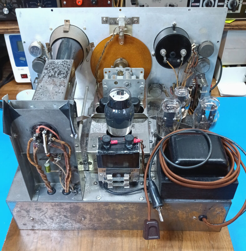
The top is complete and all the tubes are installed. I found an original 6L6G to replace the bad one. I also made a simple cardboard battery box for the two "C" cells for the 3-volt battery.
I need to make a replacement plastic hairline for the wavemeter dial because the original is curling and rubbing the dial face. It will eventually scratch the dial if I don't fix it. I tried heating and straightening the original hairline but after a few days it started curling again. |
|
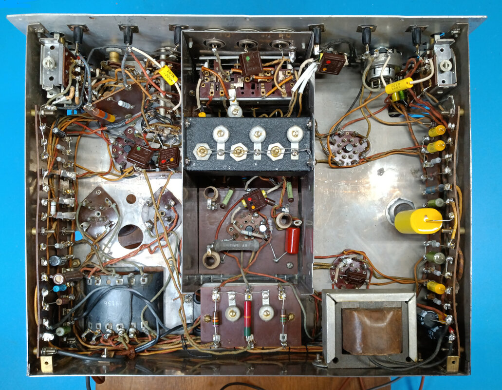
A look under the finished chassis. It's ready for the initial power up with the isolated variac and dim bulb tester. There are a lot exposed terminals with high voltage and AC power present, so great care needs to be taken when working on an instrument like this.
|
|
It's alive again but initial testing has revealed there are still some issues to troubleshoot. The scope trace was almost off the bottom of the CRT screen and the Vertical Position had to be turned to its max clockwise position just to see it.
Then a couple of times the trace jumped off the top of the screen and Vertical Position control no longer had any effect on the trace at all. Then it jumped there and stayed. These vertical issues had two separate causes. |
The trace jumping off the top of the screen was caused by an intermittent short in the 3000pF mica capacitor which is in parallel with the 0.02uF cap that feeds the vertical signal from the 6L6 output to the CRT's vertical plate. The mica cap is also supposed to block the DC plate voltage from the 6L6, but it finally shorted completely.
The other problem of getting the trace centered is a bit odd. The scope circuit in the 560 is almost identical to the 560-A, with a couple of exceptions. One of these exceptions is a 2.7MΩ resistor in series between the CRT vertical plate and the wiper of the Vertical Position potentiometer. In the 560-A this is a 1.5MΩ resistor and if I substitute a 1.5Meg in the 560 the trace can be centered, but the voltage at the vertical plate keeps drifting up for about the first 20 minutes or so after being powered on. The 2.7meg was factory so it must have worked originally, which makes me think there's another as yet undiscovered issue.
The other problem of getting the trace centered is a bit odd. The scope circuit in the 560 is almost identical to the 560-A, with a couple of exceptions. One of these exceptions is a 2.7MΩ resistor in series between the CRT vertical plate and the wiper of the Vertical Position potentiometer. In the 560-A this is a 1.5MΩ resistor and if I substitute a 1.5Meg in the 560 the trace can be centered, but the voltage at the vertical plate keeps drifting up for about the first 20 minutes or so after being powered on. The 2.7meg was factory so it must have worked originally, which makes me think there's another as yet undiscovered issue.
Another scope problem was the Intensity control had no noticable effect on trace brightness. It's supposed to be 200KΩ, and it's marked 200M, but it only measures 112KΩ. The closest pot I have is a 300KΩ, but it works and the intensity is now fully variable.
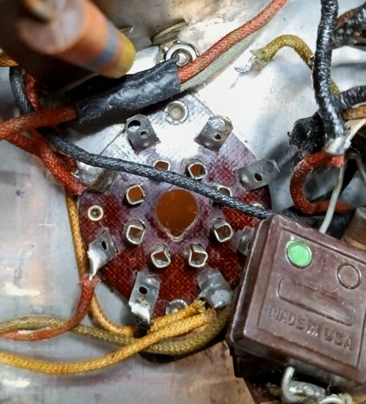
It seems there's all manner of odd problems with this Instrument. Another one of those problems was the negative high voltage #80 rectifier. Normally I just rotate a tube on its socket until it lines up and drops into the holes, but it turns out that someone in past days had forced this tube into the socket in the wrong orientation, which enlarged one of the small holes, so now the tube can be inserted two different ways. Put it in the wrong way and there's no negative high voltage and the scope gets all screwy.
Also, on the schematic there is a series voltage divider network from B+ to ground, consisting of 25KΩ 10W, 10KΩ 2W and 25KΩ 1W resistors. The tap off the 25KΩ 1W resistor is the plate voltage to the voltmeter's 6J5, as well as the screen voltage to the 6SJ7. It's labeled as 100-volts on the 560 schematic, but as only 85-volts on the 560-A diagram. However, in the actual circuits of both the 560 and 560-A the original resistor was 130KΩ 1W. In the 560-A someone paralled a 33K resistor with it to bring it down close to 25KΩ. The 130KΩ resistor gives about 110VDC and the 25K around 85VDC.
|
The voltmeter also has problems, as well as the video amp and the wavemeter. While checking resistances in the voltmeter circuit there was yet another really odd issue. The 6J5 tube socket has around 5 Megohms of leakage between the tube pins and ground even with the wiring unsoldered and the tube pulled. This leakage is messing with the 15MΩ voltage divider for all the ranges, but after cleaning the socket with non-residue electronic spray cleaner it cleared up the problem. There must have been some contamination on the socket wafer, probably from either the rust remover used on the chassis or the Deoxit that was sprayed on the contacts.
I thought I was finally ready to calibrate the voltmeter, but now the Zero Volts control can't bring the needle all the way down to zero. It doesn't have enough adjustment range. |
The voltmeter bridge would not balance without altering some resistor values, so there must be something still wrong with it. The 6J5 tube had tested good, but I installed a new tube anyway and was then able to set zero and calibrate without changing any resistor values except the 130KΩ B+ divider resistor mentioned above. In the end it was basically a tube issue. The voltmeter calibration steps are listed over on the 560-A page.
|
The vertical amp does work, but is breaking into low frequency oscillation (like motorboating in an audio amp) when the gain is advanced beyond about 80 on the Vertical Gain control. It does this on the Video and RF inputs, but not the IF or AF.
The problem was originating in the first 1852 amplifier and the fix was to add another 8uF electrolytic capacitor in parallel with the existing 8uF cap at the plate's power supply decoupling resistor. Now the amplifier is stable all the way to 100 on the Vertical Gain control. |
|
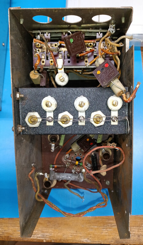
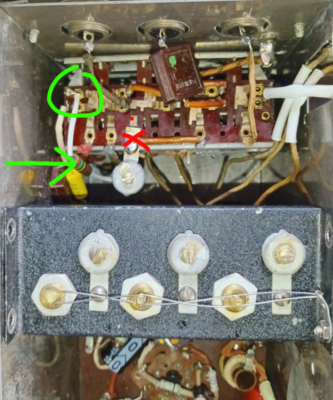
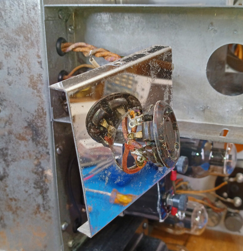
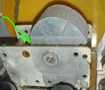
The wavemeter was not working on any band and after looking at it with another scope it was easy to see the wavemeter was actually functioning but was not being connected back to the amplifier. After tracing out the wiring from the pushbutton switches I found what appears to be a factory wiring error.
The input signal from the RF input is fed to the wavemeter through a 2-12mmfd variable trimmer capacitor. According to the updated schematic there is a 350KΩ ohm resistor from the wavemeter side of this trimmer cap back up to the top left contact on the Video pushbutton, but the resistor is not there and a jumper installed in its place was miswired to the input side of the trimmer, effectively bypassing the wavemeter (the jumper went from the top left contact in the green circle over to the top terminal of the trimmer at the red X). The jumper looks original and matches the other switch jumpers, so the resistor may be one of the updates to the schematic. |
Instead of just moving the jumper to the bottom of the trimmer, I installed the missing 350K resistor (green arrow in pic). The wavemeter now works, but still needs to be aligned.
|
|
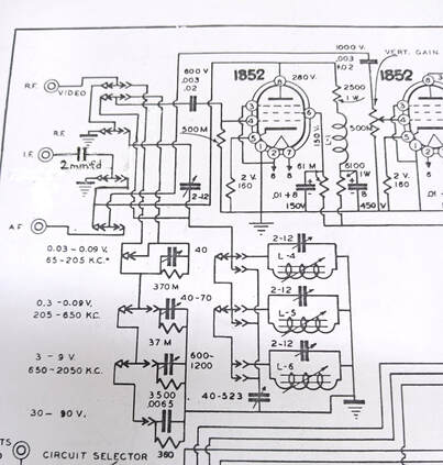
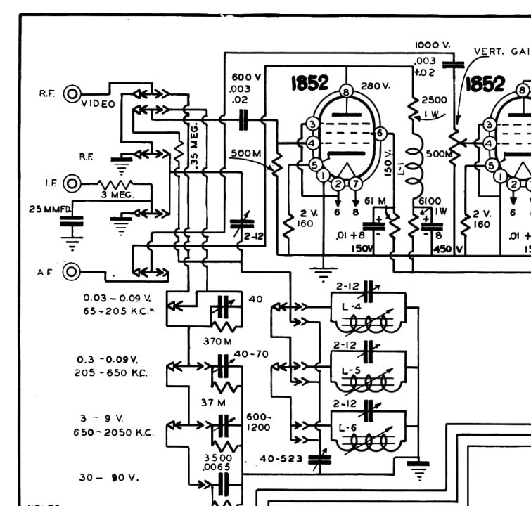
Speaking of schematics, the only one available online is dated 9-6-1939, and updated on 1-14-1940, and is drawing number is 2164-C. Most of this schematic matches this Vedolyzer, but it doesn't match the IF input circuit. I suspect this instrument was probably built before the schematic update. In the first photo I changed the input section of the schematic to reflect how this 560 is actually wired. The second pic is the original schematic for comparison.
In this unit the IF signal passes through a 2mmfd mica capacitor and is routed through the switches to the AF input path. It bypasses the first 1852 amplifier and the Wavemeter, going straight to the Vertical Gain control on the grid of the second 1852.
The wavemeter was only active when the RF pushbutton was selected and the function switch set to RF3 or RF9, but I think the IF input really should work with the Wavemeter, too. So I moved the IF to AF jumper on the switches and reconnected it at the Wavemeter input, which is how it's wired in the updated schematic. If bypassing the wavemeter is desired, it is only necessary to press the fourth button which disconnects the wavemeter from both the RF and IF inputs.
The multiplier attenuator switches are only active when the Video input button is depressed, which matches the schematic. The RF, IF and AF inputs use only the Vertical Gain to control signal levels.
|
Although everything is working now, I thought there was still something odd going on in the scope section and I finally figured it out. I pulled the 1.5MΩ resistor in series with the vertical plate and started making some ohms measurements. I found there was a couple of megohms leakage from the vertical plate to ground, the same issue I had with the 6J5 socket. The CRT was pulled to get the socket out for a thorough cleaning with alcohol and non-residue electronic cleaner which cleared up the leakage. Now there's no voltage drift on the vertical plate and the trace centers up just fine with the original 2.7MΩ resistor installed.
One last small issue in the scope was the Focus control had to be adjusted to almost full clockwise to bring the trace into focus. I had the same problem in the 560-A, and the solution is to change the 100KΩ resistor that is between the Focus and Intensity controls to 200KΩ. |
|
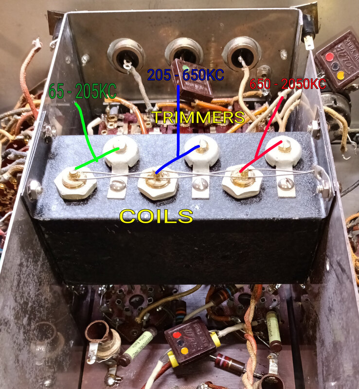
The wavemeter alignment is similar to aligning a radio. There are three bands, 65-205KC, 205-650KC and 650-2050KC The coil is adjusted at the low end of the selected band, and its trimmer is adjusted at the high end.
|
|
|
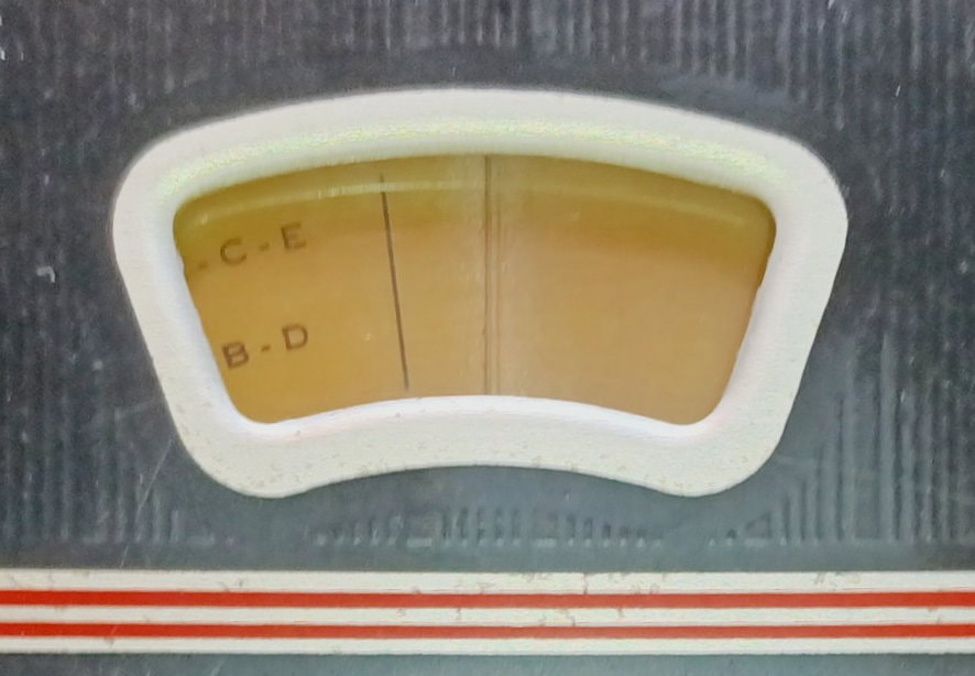
There is still one final issue calibrating the wavemeter, and that is getting the wavemeter dial to track the frequency correctly. There is an alignment line on the low end of the dial meant for aligning the dial to the hairline when the capacitor is fully meshed, but it is not correct for this 560. This same dial is used on other Supreme RF generators so the dial mark may be for those.
The tracking is off across the band, but it's at its worst on the high end, so I'm aligning the dial to the variable capacitor at the top end. To align the dial correctly I rotated the tuning capacitor until the rotor plates were almost out of the stator plates, but still just very slightly meshed (the area the green arrow points at in the pic). I then aligned the upper end of the scale (the 65/205 line) to the hairline and tightened the dial screws on the capacitor shaft. When the tuning capacitor is fully meshed this puts the dial's alignment line about 1/4” or so to the left of the hairline.
If the tuning capacitor is meshed too much or too little one or more of the band trimmers won't have enough range to adjust the top end frequency to its dial mark. Once the dial is set correctly the tracking is very close.
The 2-12mmfd trimmer for the wavemeter input also affects the dial tuning at the high end of the bands. Originally it was set to about one turn from max CCW rotation and I found this to be correct by doing a preliminary alignment and testing how different settings affected top end alignment. Once I had the trimmer set, I performed another alignment of all three bands without touching it.
This is the trimmer that would have been accessed through the front panel hole in the 1939 photo of the Vedolyzer in the ads and catalog.
This is the trimmer that would have been accessed through the front panel hole in the 1939 photo of the Vedolyzer in the ads and catalog.
|
|
The chassis is pretty much done so I'm now switching gears a bit to replacing the missing piece of oak in the cabinet's bottom, regluing all the joints, and sanding off what's left of the old clear lacquer finish. It will be refinished to match my other Supreme instruments with a golden oak stain and a clear matte enamel top coat.
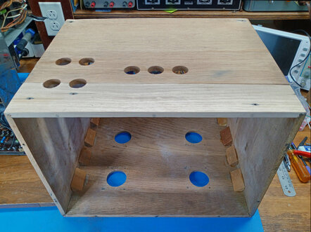
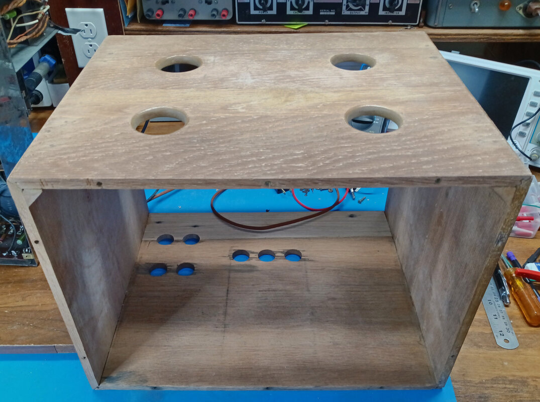
The oak board to replace the missing piece on the bottom came from a pallet. It was 1/2" thick, but the cabinet sides are only 3/8", so I had to hand plane it down to match. To cut the matching half of the vent holes I temporarily clamped a scrap board to the new piece before drilling the holes.
The oak board to replace the missing piece on the bottom came from a pallet. It was 1/2" thick, but the cabinet sides are only 3/8", so I had to hand plane it down to match. To cut the matching half of the vent holes I temporarily clamped a scrap board to the new piece before drilling the holes.
|
Other parts replaced while chasing down issues include the 6J5 tube, a 3000mmfd mica capacitor that shorted, and the bad Intensity potentiometer. A 350KΩ resistor was added in the wavemeter (as shown on the schematic), an extra 8uF electrolytic was added to suppress motorboating in the first 1852 amplifier, the 2.7MΩ vertical plate resistor was reinstalled, and the original 130K voltage divider resistor was changed to 25KΩ as specified in the schematic, and as mentioned above the warped plastic hairline was also replaced.
And I have a Supreme model 576 RF generator that uses the exact same dial as the wavemeter in the 560. It's in nicer condition than the one in the 560 so I swapped them. It also uses the same variable capacitor, and its 5 to 1 gear reduction is smoother than the one on the original capacitor, so I swapped them, too. |
For the cabinet I purchased new hardware for mounting the front and rear panels, small brass screws to replace the tacks holding the four metal screens over the top vent holes, and new screws for the new rubber feet.
|
|
|
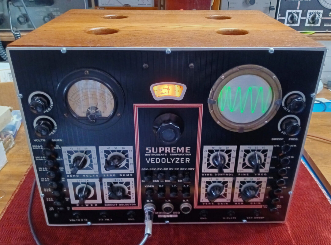
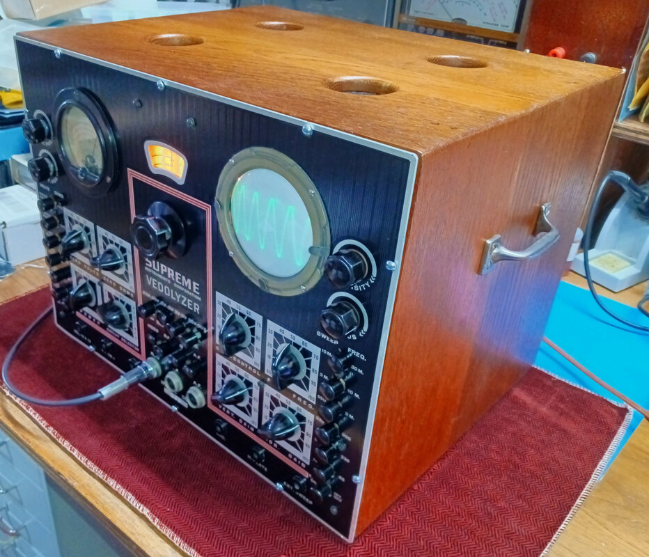
The completed 560 Vedolyzer. I think I spent almost as much time chasing down weird issues as doing the actual rebuild, but in the end it's working very well. I already have a nice 560-A so I don't really need another one on the bench, but this original 560 is even more rare than the 560-A. I couldn't pass up the opportunity to restore it and learn a bit more about both the Vedolyzer and Supreme.
The 560 and 560-A Vedolyzers, along with the 561 AF-RF Metered Combination Signal Generator, and the 562 Audolyzer, are my absolute favorite vintage test instruments.
The 560 and 560-A Vedolyzers, along with the 561 AF-RF Metered Combination Signal Generator, and the 562 Audolyzer, are my absolute favorite vintage test instruments.
Page created 9/22/2022
Last updated 12/5/2022
Last updated 12/5/2022
