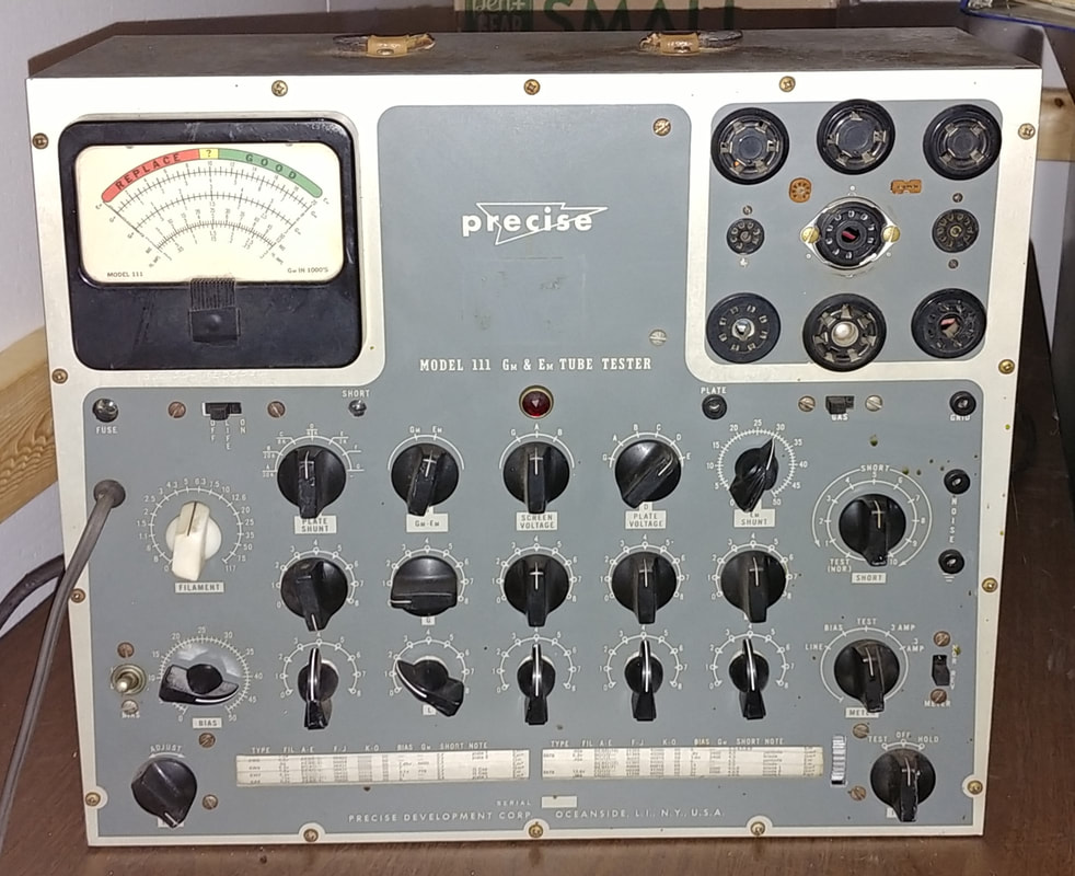
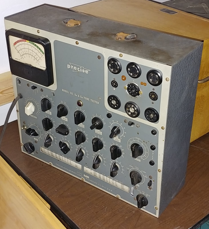
Precise Model 111 Em and Gm Tube Tester
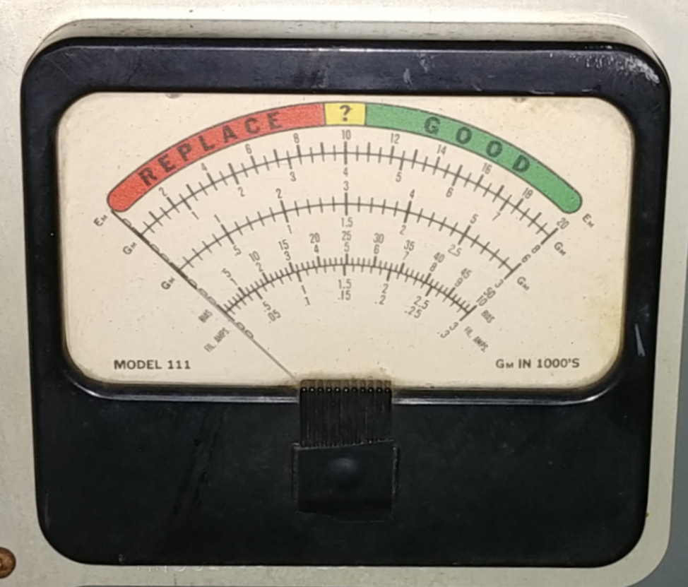
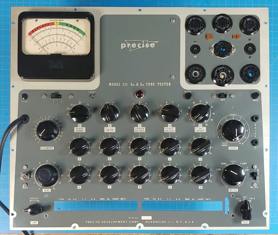
The model 111 is both an emission (Em) and transconductance (Gm) tube tester from the 1950's. A few of it's capabilities include measuring filament current and grid bias, use of 6 different plate volages and different grid signals, and has shorts, gas and life tests. Overall it's a very capable tube tester.
|
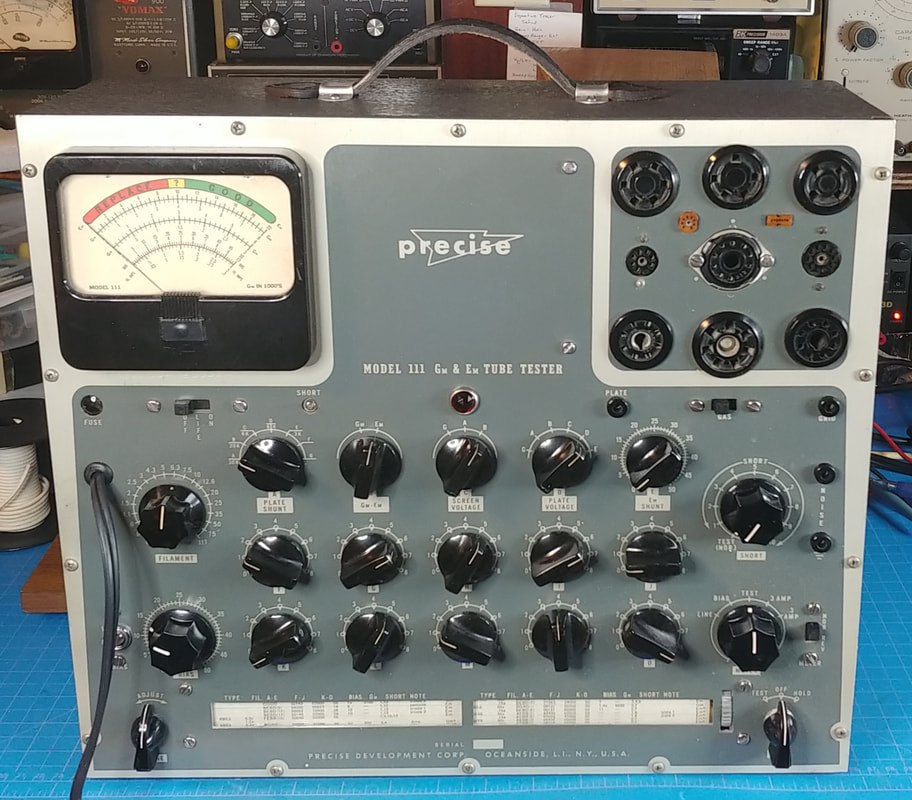
The leather handle is broken but should be easy to replace as soon as I measure the length. The case is dirty but not scratched up, so it should clean up nicely.
Someone put a white knob on the filament selector, but it's cracked and slips on the shaft, so I hope no one tried testing a tube with it like this. No telling what filament voltage they might have selected. |
|
A full page magazine ad from January 1956 for the model 111. The first reference that I could find for the 111 is in a May 1954 ad. The ad also mentions the Precise 1954 catalog, but a cursory search of the web did not turn up anything on it.
There are a number of pdf docs available from several online sources that include construction, calibration and instruction manuals, in addition to some period ads. I'm glad people have made these available, but unforunately most are missing pages, or out of order, or all mixed together. With a bit of patience though, it is possible to piece together a complete set of books for the tester, it just requires some sorting and pulling pages from different docs to come up with a full set in the right order. |
|
After removing the tester from its case, the first thing I did was pull the tube roll chart so it wouldn't get damaged during repairs.
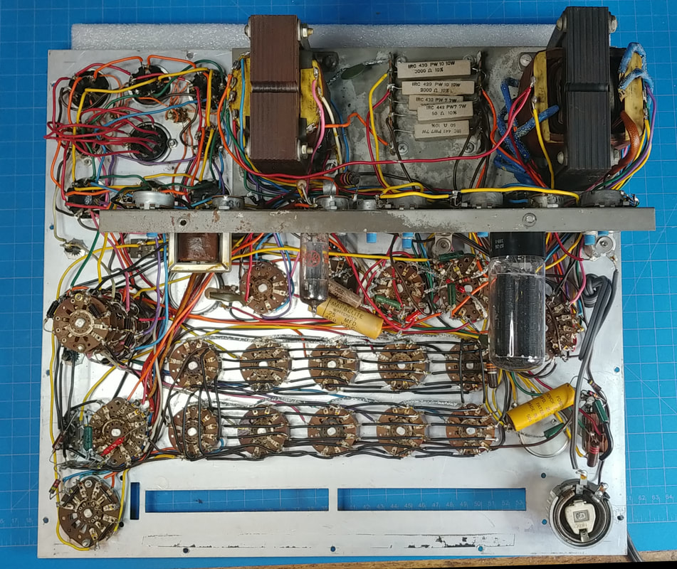
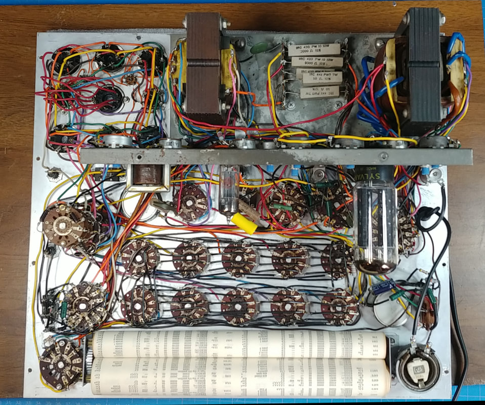
Looking at the wiring I would say this model 111 was a kit. It's not bad overall, but there are a few places that need reworked, and there are solder splatters and soldering iron burns all over the wiring. Also, there are a couple of places where someone mucked up the soldering trying to work on it, but overall it's almost completely original inside. As I was cleaning the wiring and switches I found a faded handwritten note scribbled right on the chassis that confirms it was a kit. The note says, "Finished April 5 1955". A nice little note left by the builder 67 years ago. |
|
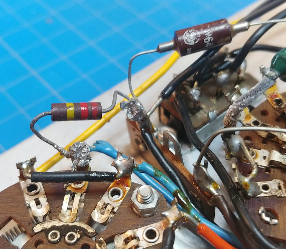
Going by the poor soldering on the 220KΩ resistor, I thought it might have been replaced. But after going through the initial calibration steps in the manual I realized the sloppy soldering is from someone tacking in the 2KΩ 10-watt resistor that is used during these calibration steps. Also, this is the worst example of soldering in the set.
|
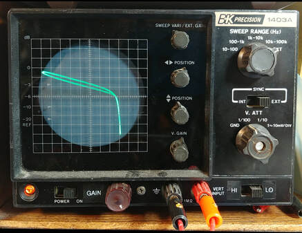
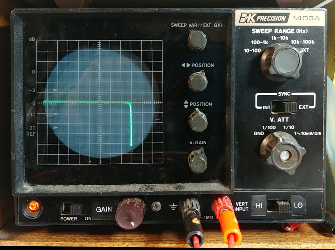
I checked the 1N64 Germanium diode on my component tracer. For comparison I also tested a new 1N34 which shows a near perfect "knee". The front to back of the 1N64 isn't as good so I replaced it. The specs of the two are not that different and it's working fine.
|
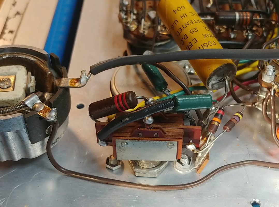
All the small selector switches on the front panel are slide switches except the Bias switch and it's obvious from the switch lettering and mounting holes on the panel that this was meant to be a slide switch as well, but looking at the soldering and the way the components are mounted it appears this switch could be original.
I looked at front panel images online and almost all have a slide switch here, but I did find one other with a toggle switch. I was going to change it, but after inspecting the round hole cut in the center of the original rectangular cutout, I think it will look better if I just leave it alone. |
There are several types of fixed resistors in the tester, including red 1% precision, green 5% carbon, old roundy style (pre-Allen Bradley (A-B)), wirewound power resistors, and even a couple of A-B carbon comps.
All three red precision resistors in this set are out of tolerance and were replaced with hand matched resistors.
All the green ones, which are described as "deposited carbon" on the parts list, are still good.
All the old roundy style are out of tolerance, or very close to it, and were replaced. I noticed that one of these, R6, is a 2.2KΩ 1-watt resistor but is mislabled as 22KΩ on the schematic.
And the wirewound power resistors are still good.
As far as capacitors go, the two electrolytics and the one waxed paper and foil capacitor are bad. The ceramic disc capacitors are still good.
|
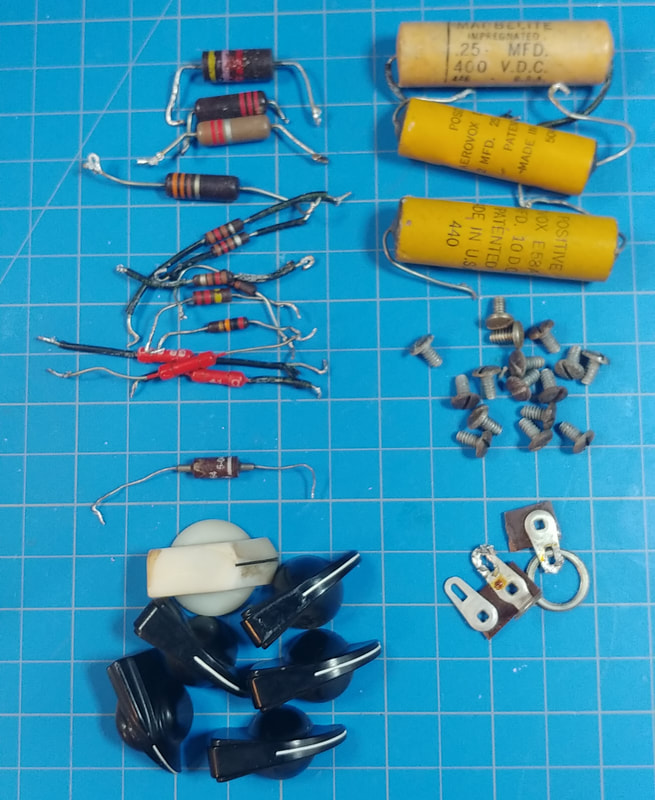
This tester did not have all its original knobs and there were six that needed replaced. One question I had though is exactly what knobs were originally on this set because Precise changed knob styles somewhere along the way.
In the January 1956 advertisement near the top of this page there are three different style knobs on the instrument shown, two chicken heads, four round fluted, and the other fifteen have rectangular tops with a round skirt. But on the covers of the manuals I have they show a 111 where all the knobs are the round skirted rectangular top style. And on the manual pages showing how to set up the controls there is yet another variation on the type of knobs. |
Since I know this tester is from 1955 I'm going with the three-knob style. And I managed to find replacements for all the missing knobs in my parts drawers, except for one of the fluted knobs, which I ordered.
|
I started testing by going through the steps in the calibration instructions for initial setup after completing the build. Everything checks out OK all the way up through balancing the plate bridge.
And calibratig the 6K and 8K scales with the 6C4 tube went by the book with just minor adjustments needed on either scale. Next a 6L6 was used to calibrate the 20K and 30K Gm scales and the Em side. And finally, the 3 Amp and 0.3 Amp filament current scales were set.
Also, the neon shorts bulb I made with the NE-2 is working fine. |
|
The tester is fully functional now and back in its metal cabinet. The case was cleaned and waxed which gave the wrinkle paint finish a new lease on life, and a new handle was installed on top. Normally the tester lays flat on its back on four rubber feet when in use. But when carrying it by the handle it sits on the bottom which has no feet, so I added four black self adhesive feet to the bottom, too. I really like this tube tester, it has a lot of good features, and it is definitely a keeper.
After using the tester for about a year I discovered an issue. One day I needed to test a 6A7 tube from a 1930's RCA tombstone radio, and that's when I found that the large 7-pin tube socket was rotated 180 degrees and thus miswired. When the tube wouldn't check I noticed the two large filament pins were at the top, not at the bottom like the other sockets. |
Page created 11/12/2021
Last edit 3/20/2022
Last edit 3/20/2022

