AN/PDR-27G Radiac Set
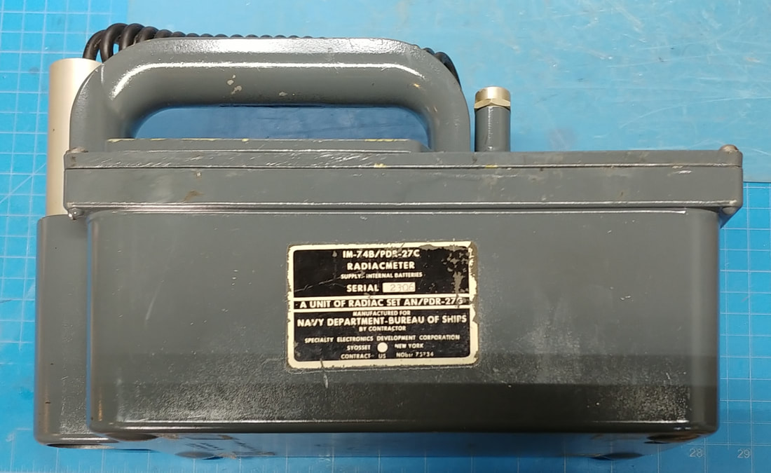
The instrument in this radiac set is an IM-74B/PDR-27C Radiacmeter, which, according to the nomenclature tag was made by Specialty Electronics Development Corp. in the 1950's.
I picked up this set a long time ago, I think it was back in the 1970's from Fair Radio Sales Co. It hasn't been powered up in maybe 10 years because of how many batteries it needs, but it was working back at that time. Now I'm sure it's time to check for leaky capacitors and out-of-tolerance resistors.
I picked up this set a long time ago, I think it was back in the 1970's from Fair Radio Sales Co. It hasn't been powered up in maybe 10 years because of how many batteries it needs, but it was working back at that time. Now I'm sure it's time to check for leaky capacitors and out-of-tolerance resistors.
|
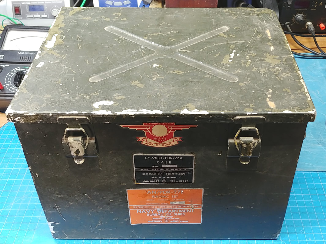
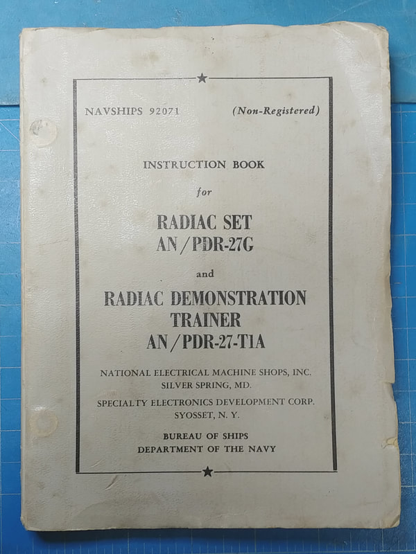
The set is housed in a gasketed metal case and has a sticker for Kelly AFB in San Antonio, Texas on it. The orange tag on the case says it is the PDR-27E Radiac Set, but the manual and the tag on the Radiacmeter both say they are part of the PDR-27G Radiac Set. So it doesn't look like it's the original case for the set.
|
|
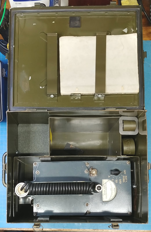
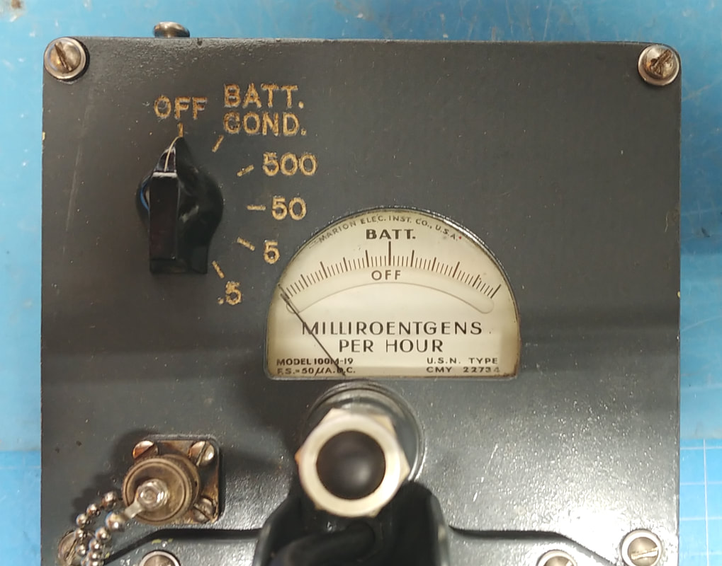
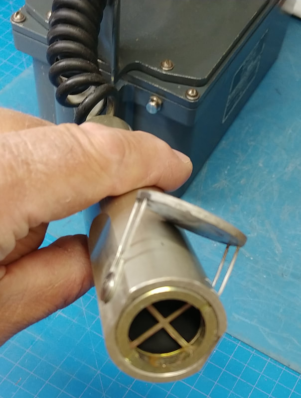
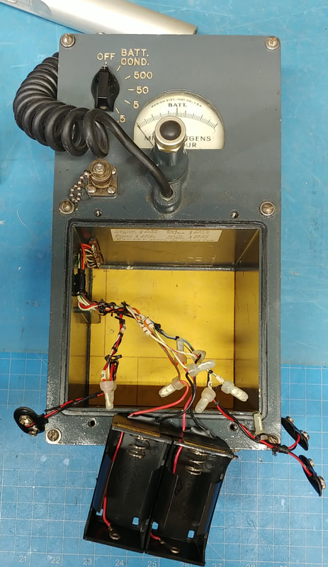
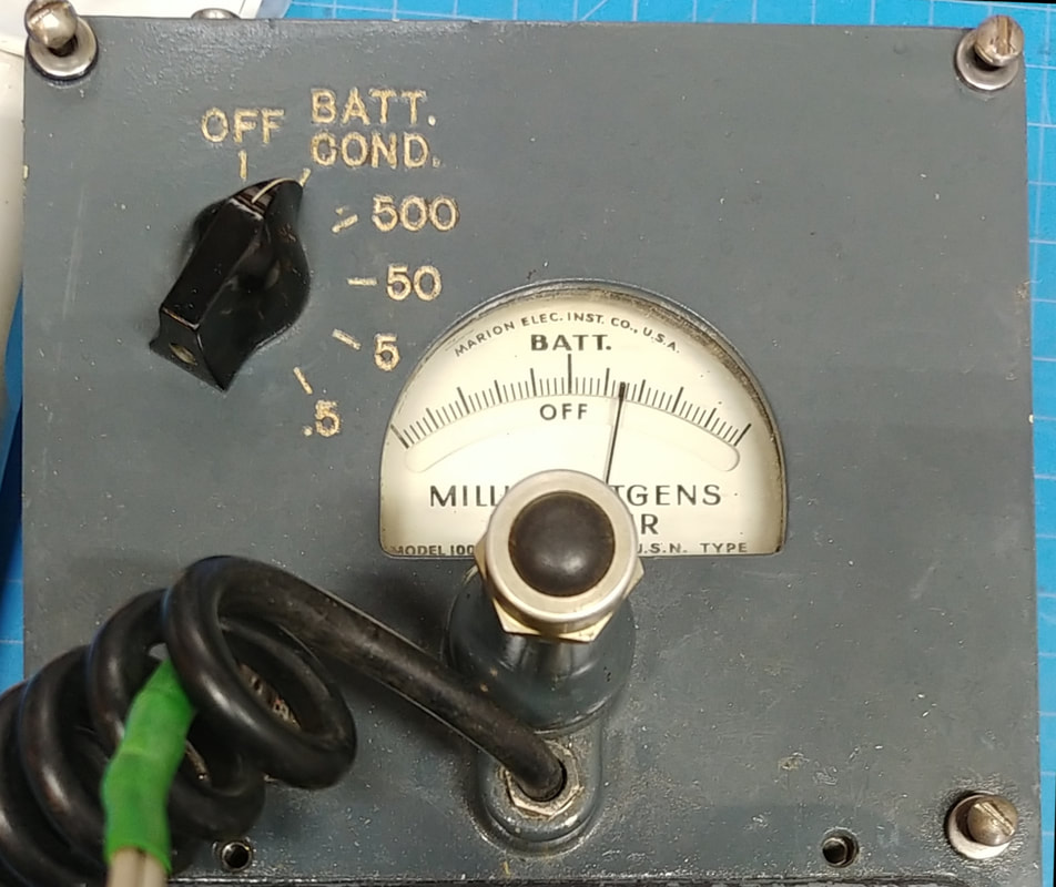
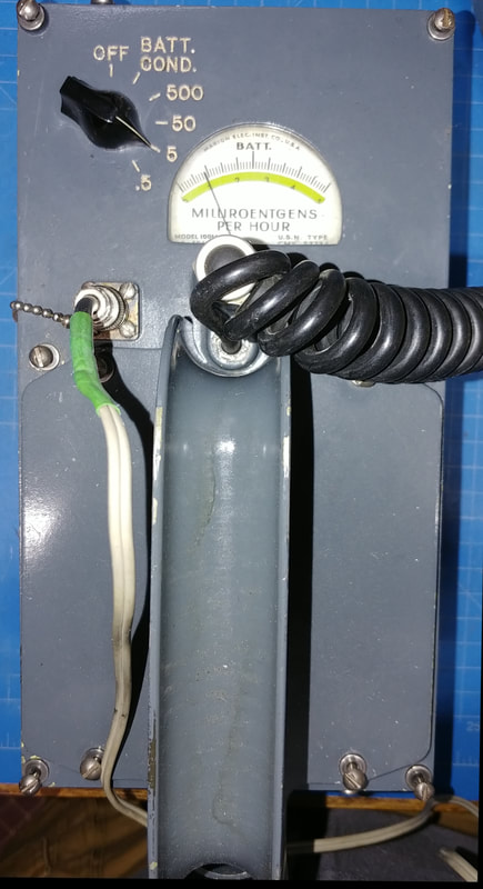
Top view of the meter in its case. The main control on top is the range switch. And there is also a lamp pushbutton to illuminate the meter. That's it for controls, only thing else on top, other than the meter face, is a BNC connector for the headphones.
The case also contains the manual and a carry strap, plus compartments for such things as the headphones and spare batteries. |
|
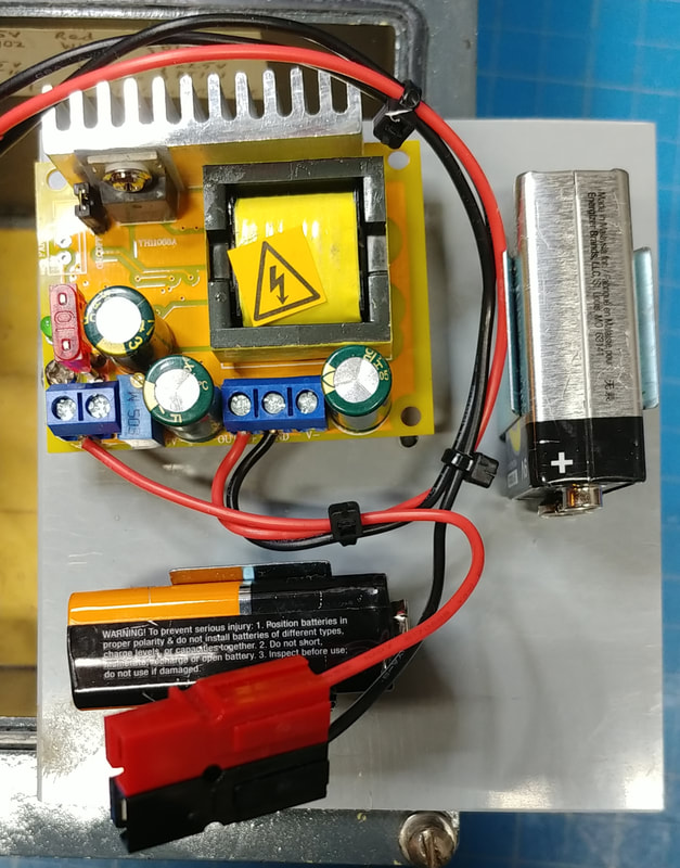
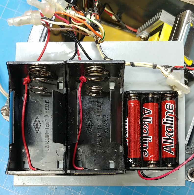
This instrument is battery powered, using two 1.5V "D" cells, plus 22.5V and 135V batteries. Years ago I updated the battery snaps and added the two "D" cell battery holder shown. Two 9-volt batteries were substituted for the 22.5V battery, and fifteen 9-volt batteries made up the 135V battery. But it's not very cost effective to use a total of seventeen disposable 9-volt batteries for power, so I'm replacing the 135V battery with a DC-DC high voltage boost converter.
|
|
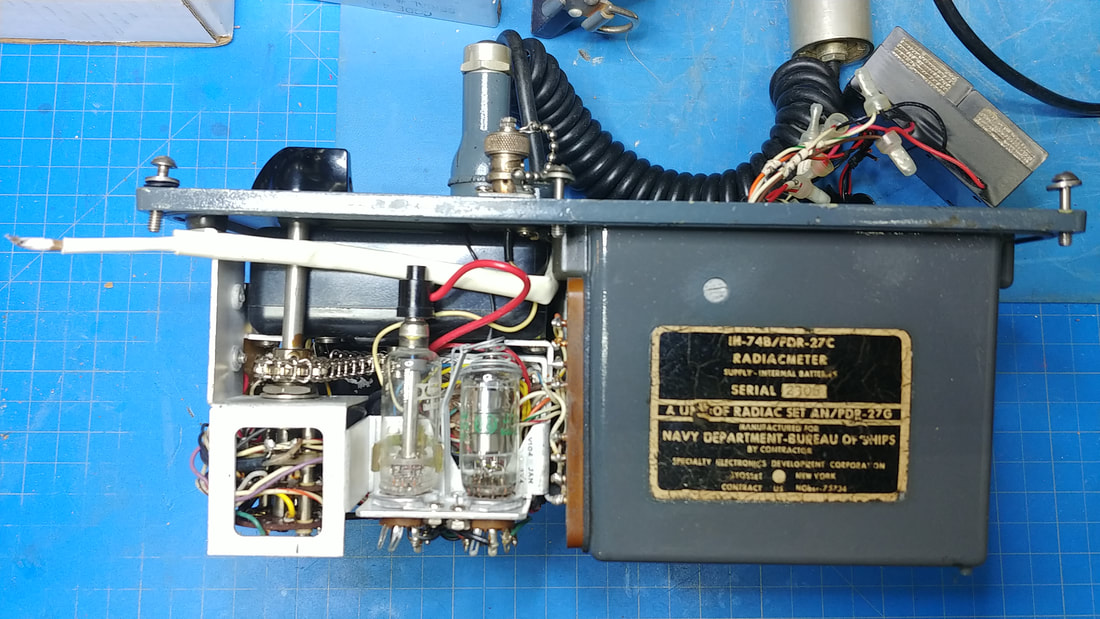
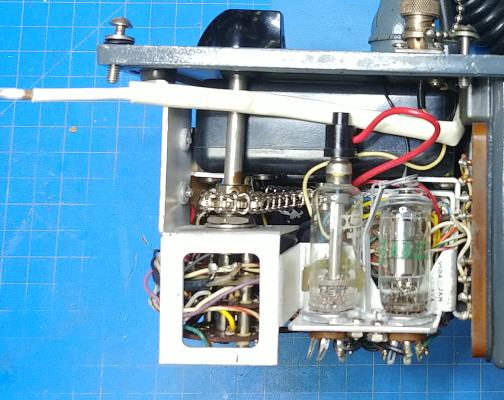
The instrument removed from its case. It has a matching nomenclature sticker to the one on the case. The white spaghetti covered wire sticking out is the center wire from the coiled shielded cable of the probe. It is rubber coated and the rubber is extremely brittle and stiff. The coiled part of the cable appears to be OK and it's just the exposed portion of the rubber coated wire that's an issue, so it's been covered with spaghetti tubing to prevent the high voltage from arcing or shorting to anything. It solders to the front wafer of the rotary switch.
|
|
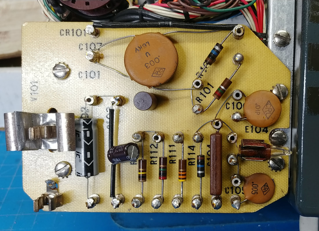
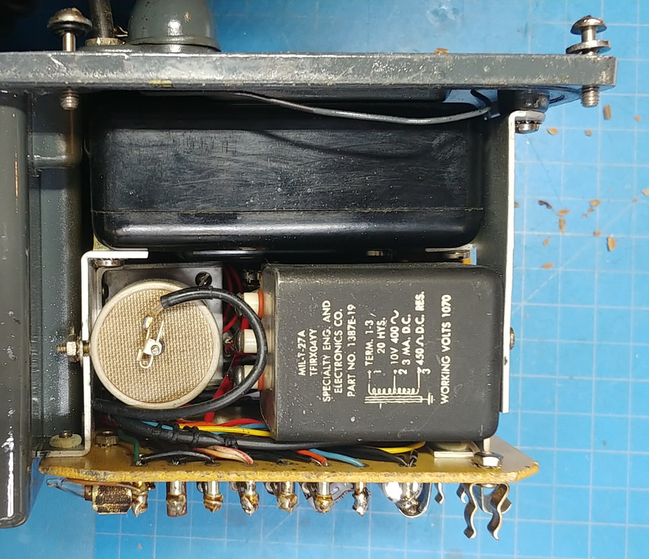
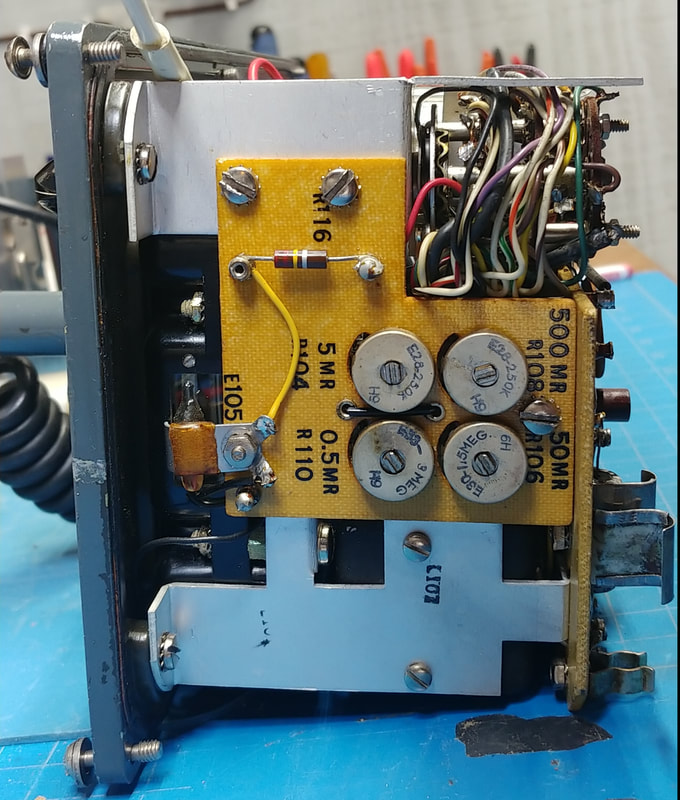
The bottom circuit board has two electrolytic capacitors, C-102 and C-103, and the high voltage selenium rectifier CR-101. Both caps were shorted, and the rectifier's forward resistance is getting very high. It measured over 200KΩ on my analog Triplett VOM. I could not get a reading in either direction using my digital meters. I suppose they were not providing enough current to the selenium rectifier. It was replaced with a 3KV PIV silicon diode. Also, all the resistors are still in spec, and V-101 has been temporarily removed to protect it.
|
This is the same model DC-DC boost converter I used in the RCA WF-12A to replace the "B" batteries. The only difference this time is I'm only using the positive DC output of the converter because I need to tie the module ground to the negative lead for the 135V battery (switched ground) in order to switch the 12 volt battery on and off using the counter's range switch. By grounding the battery to the meter's case, instead of directly to the boost module, it gets switched by the range switch without any rewiring.
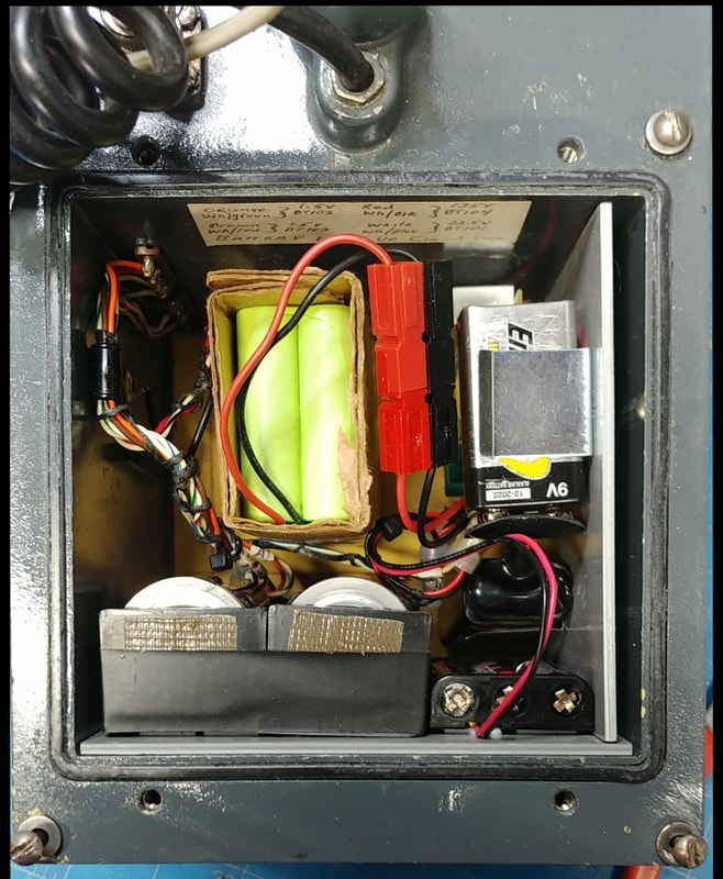
The total battery complement is now:
2 - 1.5V "D" cells for the filaments
2 - 9V batteries plus 3 - "AAA" cells in series for the 22.5V battery
1 - 12V 2000mAH "AA" NiMH battery pack to power the +135V high voltage module.
The total battery complement is now:
2 - 1.5V "D" cells for the filaments
2 - 9V batteries plus 3 - "AAA" cells in series for the 22.5V battery
1 - 12V 2000mAH "AA" NiMH battery pack to power the +135V high voltage module.
|
When first powered up the battery check was reading low at only about 1/4 scale. The battery test circuit is simply a resistor (R111) in series with BT-103 and the meter movement. Both the battery and R111 check good which only leaves the meter as the source of the problem. I guess the meter sitting idle for 10 years has not been good for it. Fortunately, after exercising the movement by repeatedly measuring a source that drives the needle to full scale it finally started responding as it should and now the battery check is over half scale, which is where it should be. But I better not let it sit for another 10 years without using it.
|
|
The counter is measuring a specimen of uraninite. This counter is reading a little lower than the Lionel, but since I don't have a verified source or calibrated meter to compare against I don't know which, if either, is more accurate. But it's not a big issue, they both work and I really don't need super accurate measurements. Just knowing if a sample is, or is not, radioactive, and relatively how strong it reads, is enough for now. If I get a chance to use a calibrated meter to check my sources I can then adjust the meters as needed.
|
Page created 4/23/2021
Last updated 5/9/2021
Last updated 5/9/2021

