
Restoring a Supreme Model 560-A Vedolyzer
The Vedolyzer was announced in June 1939 as "Supreme's conception of a new, amazingly fast and complete method of radio service". It was sold separately or in tandem with the model 561 AF RF Combination Signal Generator as a complete dynamic signal analysis system.
In a nutshell, it is the combination of a VTVM, a wavemeter, and a 3" oscillograph, and also functions as a signal tracer and multiple monitoring system. The Vedolyzer was the main instrument of Supreme's new dynamic analysis system called "See The Signal".
The first ad I have found for the original 560 is from the June 1939 issue of Service magazine where it is advertised alongside the also new model 561 signal generator.
|
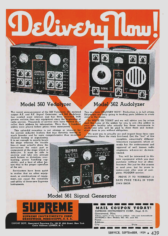
A September 1939 ad proclaims that all three of Supreme's new instruments for dynamic analysis, the model 560 Vedolyzer, the model 561 Signal Generator, and the model 562 Audolyzer, are now available for delivery, and over a hundred orders for them had already been placed, even before a price was announced.
This was state-of-the-art for servicing radios in 1939, and with a name like the "Vedolyzer" how much more Buck Rogers can you get. |
I have both a model 560 and the 560-A, and the restoration of the 560 Vedolyzer is detailed on a separate web page.
|
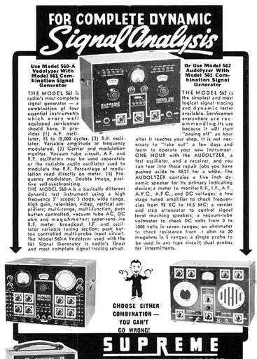
By October 1940 the 560-A was already being advertised in Radio Retailing magazine, and this January 1941 ad from Radio Service Dealer magazine offers the updated 560-A Vedolyzer in combination with Supreme's updated model 561 AF/RF generator. The 560-A also has a full page devoted to it in Supreme's 1941 catalog.
I finally found a nice model 561 to pair with my Vedolyzer and its restoration is the subject of a separate page. FYI: Check out Mr. Carlson's Lab on YouTube where he has a 4-part series on restoring a Vedolyzer, and as always he does a masterful job. His videos will be a great reference for restoring this one. |
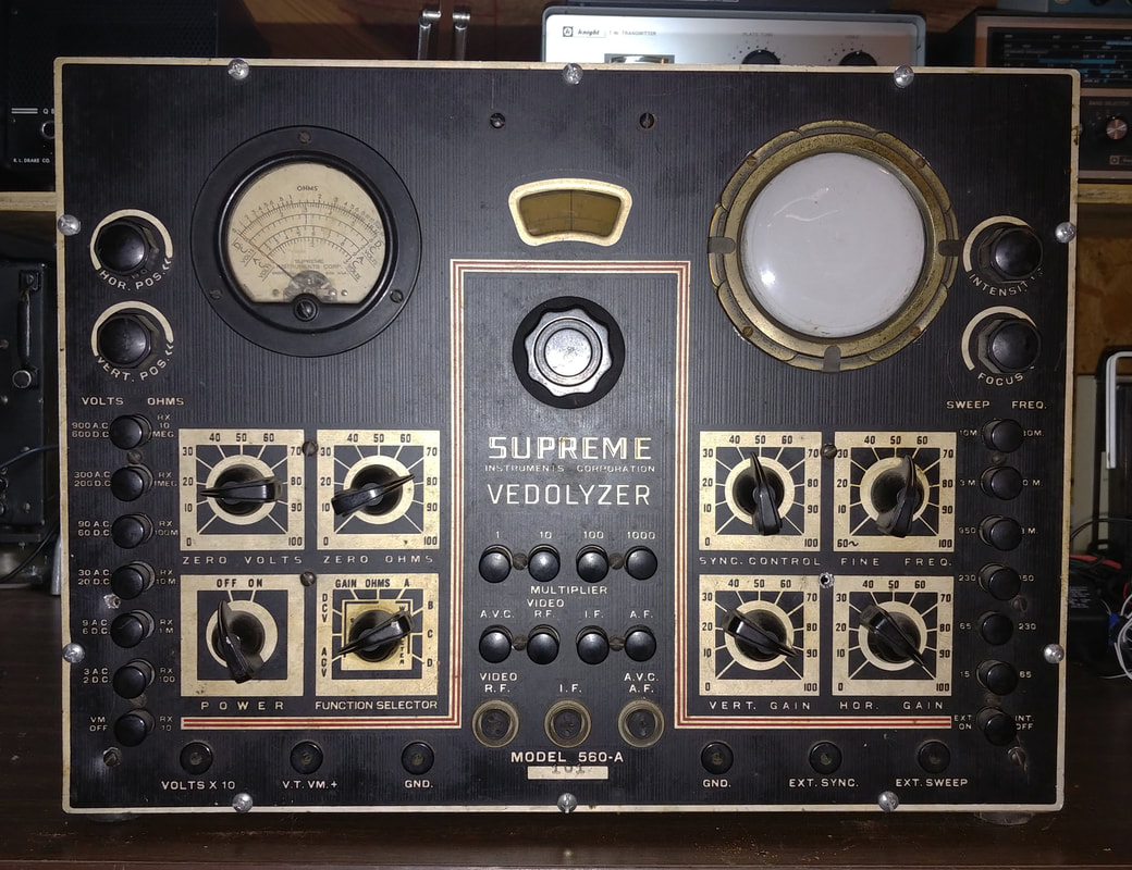
This instrument is S/N 101. I'm not sure where Supreme started with production serial numbers as companies didn't necessarily start at 1, but regardless, it is a very early "A" version, probably dating to mid or late 1940 since radio manufacturers introduced the next year's models in the Fall of the prior year. The 560-A debuted in the 1941 catalog and the 560 was only listed in their 1940 catalog. The only 560 I've seen is S/N 103, so it appears Supreme reset serial numbers for the 560-A.
The manual available online for the 560-A is from S/N 364, the one in Mr. Carlson's videos looks to be in the 400's, and I've seen a photo online of another in the 500's, so Supreme made hundreds of the "A" model. And the "A" schematic is in the September 1945 edition of Radio Service Dealer magazine (RSD), which is available online. A description of the 560-A and the schematic is also on pages 256 - 258 of the American Television, Inc. book "Radio Servicing Fundamentals" (1947, 2nd Edition).
The manual available online for the 560-A is from S/N 364, the one in Mr. Carlson's videos looks to be in the 400's, and I've seen a photo online of another in the 500's, so Supreme made hundreds of the "A" model. And the "A" schematic is in the September 1945 edition of Radio Service Dealer magazine (RSD), which is available online. A description of the 560-A and the schematic is also on pages 256 - 258 of the American Television, Inc. book "Radio Servicing Fundamentals" (1947, 2nd Edition).
|
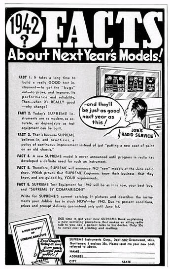
In the May 1941 RSD Supreme advised customers that the 1941 models would also be their 1942 models, so the 560-A was available at least into '42. But switching over to war production may have brought the Vedolyzer to a premature end.
|
|
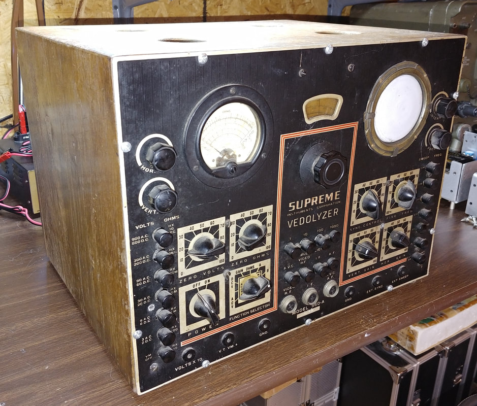
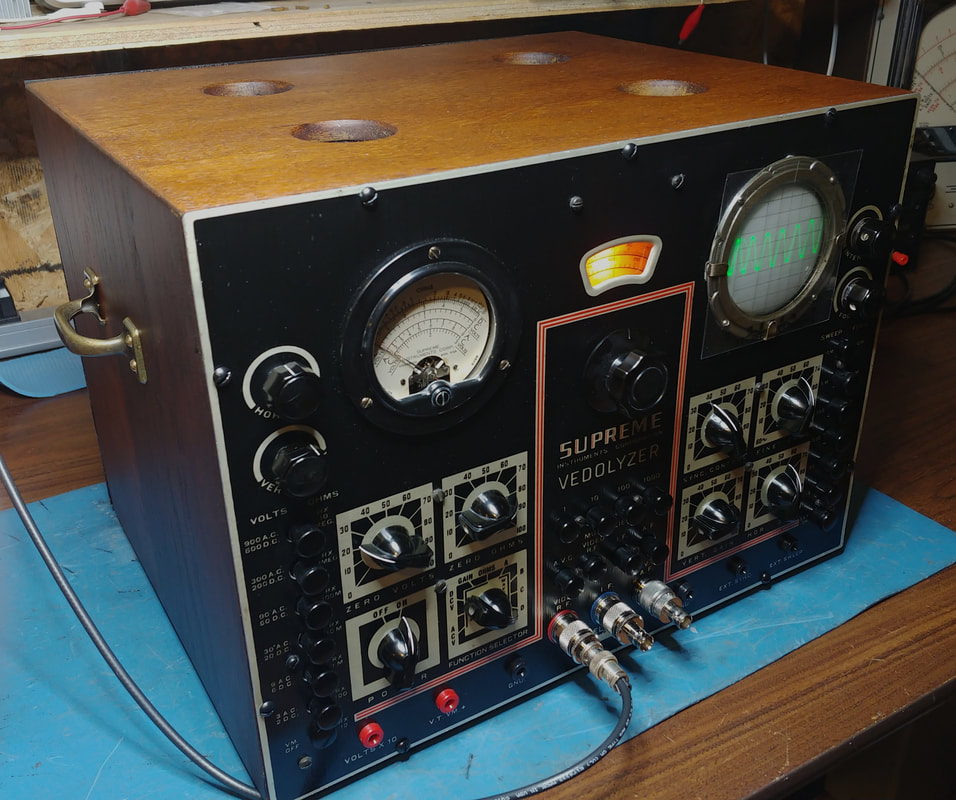
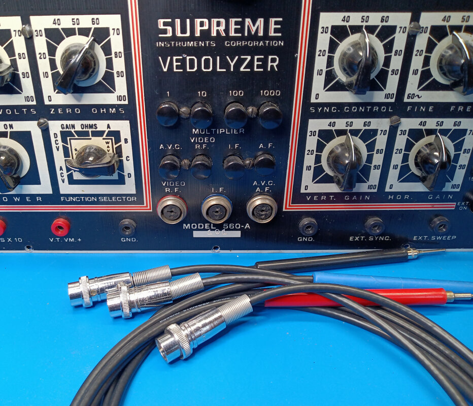
The front panel is in very good condition, no big scratches or dents, and it will clean up nicely. All the knobs are there and the only parts that might need changed are the old Amphenol microphone-style input connectors.
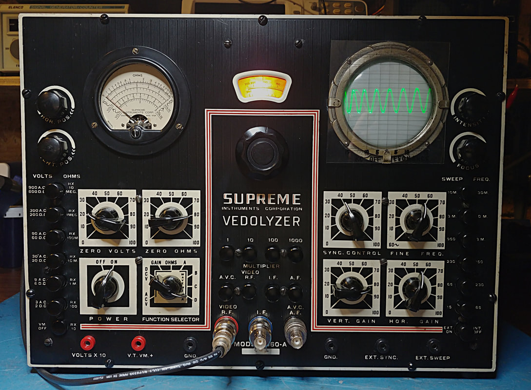
On the left side is the Vacuum Tube Voltmeter and ohm meter with push button range selection and the zero controls for the meter. The Power switch and Function Selector are right below the zero controls. Near the top left are the Horizontal and Vertical Position controls for the oscillograph, placed on the left for symmetry. |
In the center section is the Wavemeter, with a range of 65KC to 6.5MC, and is used to measure IF frequencies. Below the Wavemeter are the Multiplier push buttons, the input signal selectors, and the three input jacks for the RF, IF and AF probes. And on the right side is the 3" oscillograph with Focus and Intensity controls near the top, the Sync Adjustments and Vertical and Horizontal Gain controls below, and Sweep speed selector buttons down the side.
|
The oak cabinet is sound and only needs some minor gluing before refinishing.
|
|
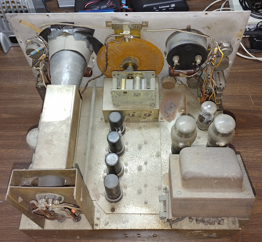
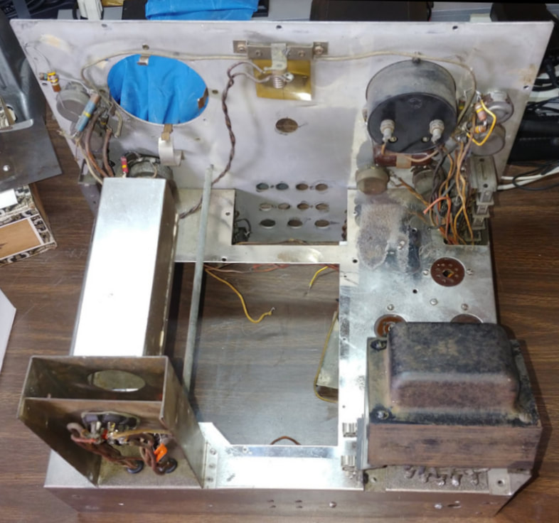
Inside, the chassis is covered in dirt and a thick film, probably residue from cigarette smoke. The chromed chassis is spotted with some rust, and battery acid has created a couple of larger rusty places, one on top of the chassis and one underneath. I'm going to have to disassemble most of the unit just to get everything cleaned and polished.
|
|
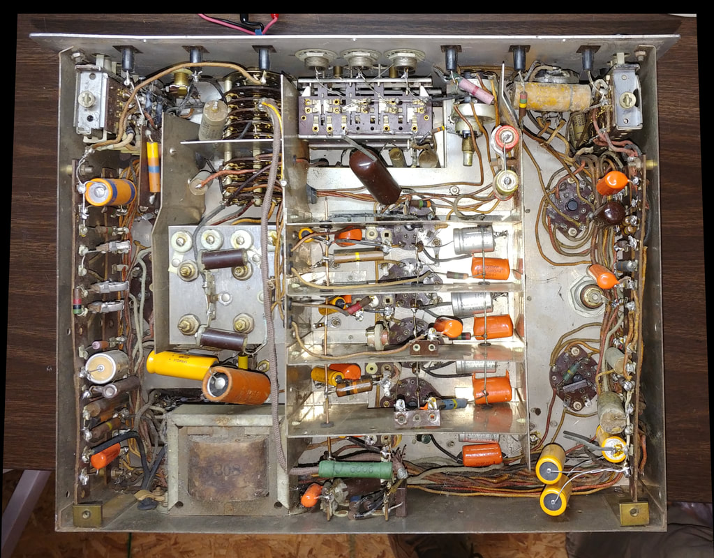
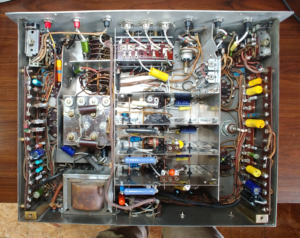
Someone has definitely had their fingers in this thing. A lot of capacitors have been changed, and some resistors, but they didn't replace all the old paper caps or electrolytics. It appears they were just trying to get the scope section working. And the workmanship was not very good either: long leads, tack soldering and cold solder joints abound.
I see there are also numerous wires and capacitors just hanging loose and one resistor from the video amp even fell out the bottom when I pulled the chassis. Screws and spacers are also missing and I noticed a ground lug hanging in mid-air because its screw was gone. I checked the date codes on the replacement Sprague electrolytics and they're all from 1984, which gives a rough idea of when this mess was made. |
|
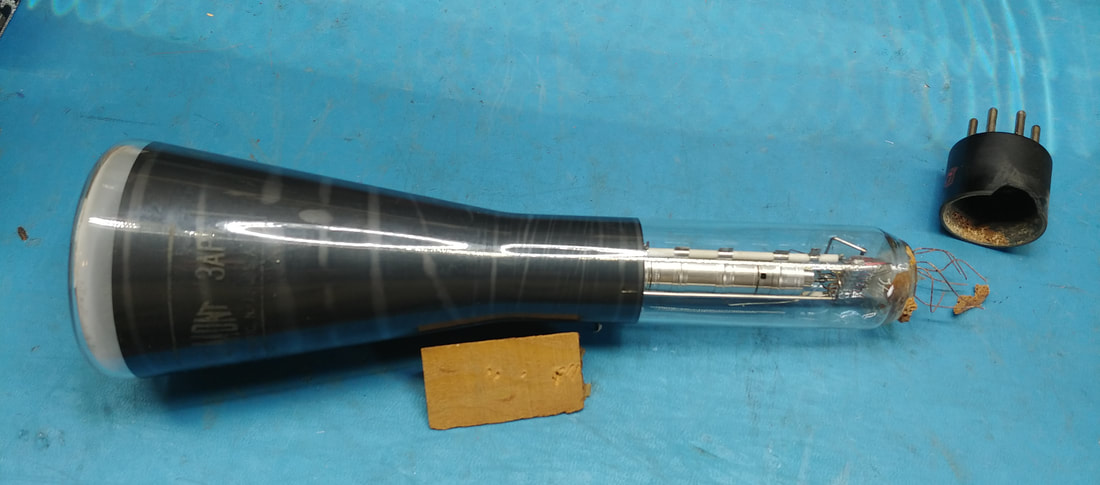
Well, this is a bit disappointing. Someone, who obviously didn't have a clue what they were doing, has pulled the 3AP1 CRT right out of its plug. They apparently were trying to get the tube out of the socket by pulling on the glass body. Looking at the tube's wires, I see they were just soldered at the very tips of the pins and the solder joints gave way before the wires broke, thankfully I guess. The plug's pins were stuck in the socket and after loosening them up with a little WD-40, I carefully pried out the plug using a small screwdriver.
|
This is why you don't pull on the glass tube when removing a CRT. Now I have to try to figure out the pin wiring by peering through the CRT glass to see if I can trace which wires connect to which electrodes. The filaments test good, so it will probably work just fine if I can sort out the rest of the wiring.
|
With the CRT out of the way the video amp and Wavemeter subchassis have been pulled for cleaning and rebuild. The chrome is not in great condition but cleaning has restored at least some of its former luster. Next the face plate needs to come off for cleaning and to pull the left and right switch banks.
|
|
|
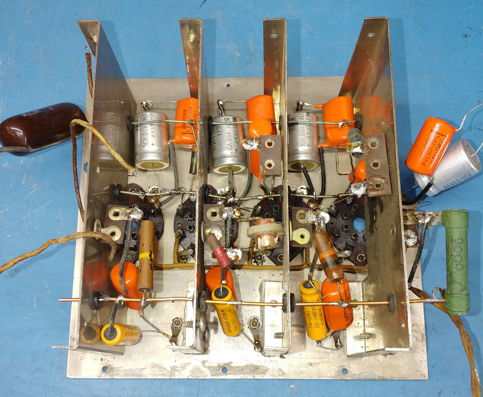
This is about as clean as the chrome is going to get, but it's still a lot better than when I started. The video amp will be stripped down and rebuilt with mostly new components since almost all of the old resistors are out of tolerance and have to go anyway, and most of the soldering is pretty bad, well, except for the parts I see that aren't soldered at all.
Interestingly, the video amp specs of the original model 560 claimed a flat bandwidth of 4.5MHz, but the updated 560-A only claimed 2.5MHz.
Interestingly, the video amp specs of the original model 560 claimed a flat bandwidth of 4.5MHz, but the updated 560-A only claimed 2.5MHz.
|
|
There are several components in the Wavemeter to check and replace. I removed the Wavemeter coils and stashed them in a cabinet until I'm finished under the chassis. Too many delicate wires there to take a chance leaving them in harm's way in the chassis.
|
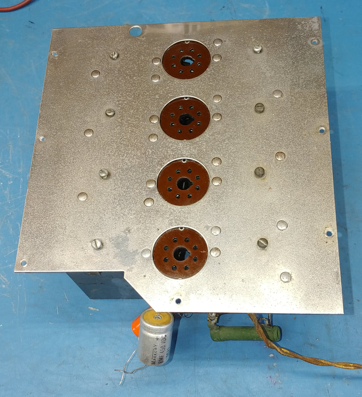
Not much left on top of the main chassis now that the front panel is off. I will start rebuilding this section first and then move on to the other modules afterwards.
I already see the Horizontal Position control is not original and needs replaced. It's very hard to turn, cleaning would probably fix that, but it's not even the correct value. The other pots look original and all will get cleaned. |
|
Now that I'm actually replacing components under the chassis I am really discovering just how hacked up it is. I was wondering why all the lacing had been cut away from the wiring and now I know after some late nights tracing down wiring and component mistakes. Plus I have to clean and resolder every solder joint that whoever did this has touched. Many terminals are just covered in globs of solder.
I also see there is a switch on the Horizontal Gain control that is not shown on the 560-A schematic. But I did finally find it on the old model 560 schematic. |
Apparently it was carried over from the 560 design and looks to be a remnant of Supreme's continuous design changes, as the switch really has no purpose in the 560-A. The switch connected the CRT's horizontal plate to either the output of the internal horizontal amp or an external input jack labeled Horiz. Plate. But there is no Horiz. Plate jack on the 560-A so I just soldered the wire back to the opposite switch terminal, and the switch does nothing now.
|
|
In all I found two bad potentiometers. One is the aforementioned Horizontal Position control and the other is the Meter Zero pot. On it the wiper connection is a coiled "spring" around the center shaft and solders to the center terminal. The spring wire had broken at the terminal, but I was able to solder it back and save the pot.
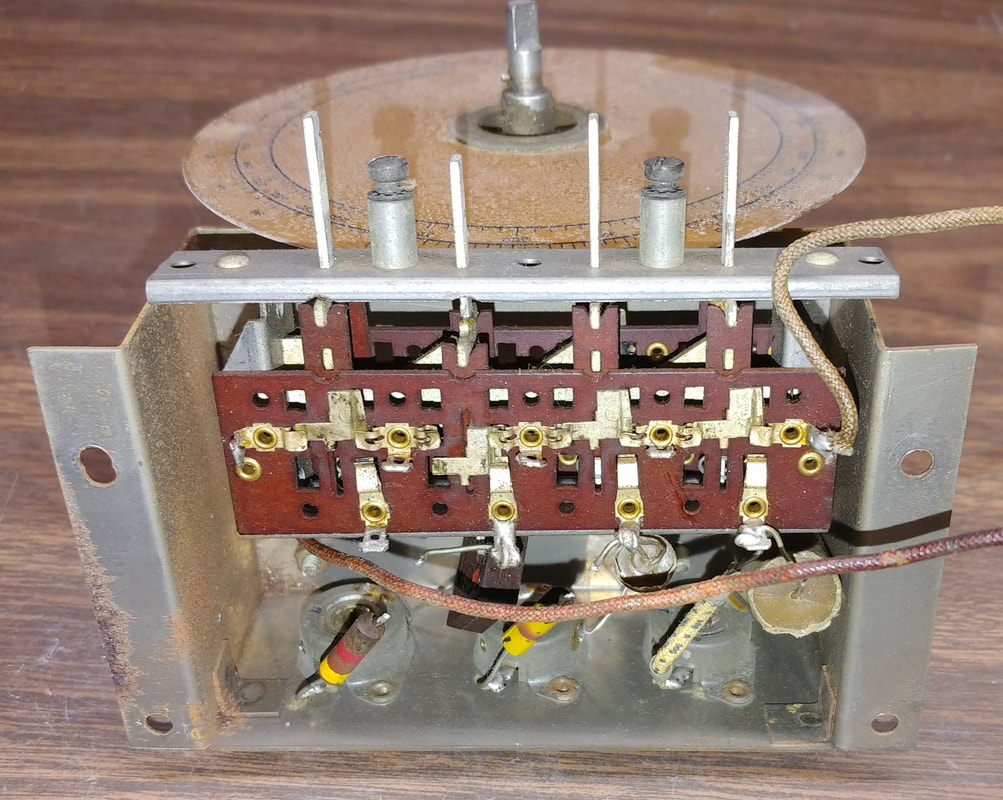
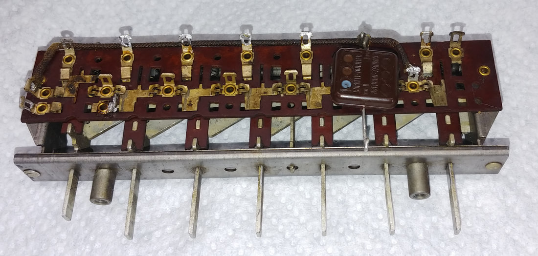
The left and right push button racks have been cleaned and are operating smoothly, but I notice on both sets that there were originally rubber pieces around each shaft at the inside tops of the plungers, to keep them from hitting the frame with a loud 'clack" when they pop up. I'll see what I can do about fabricating replacements.
The left and right push button racks have been cleaned and are operating smoothly, but I notice on both sets that there were originally rubber pieces around each shaft at the inside tops of the plungers, to keep them from hitting the frame with a loud 'clack" when they pop up. I'll see what I can do about fabricating replacements.
|
|
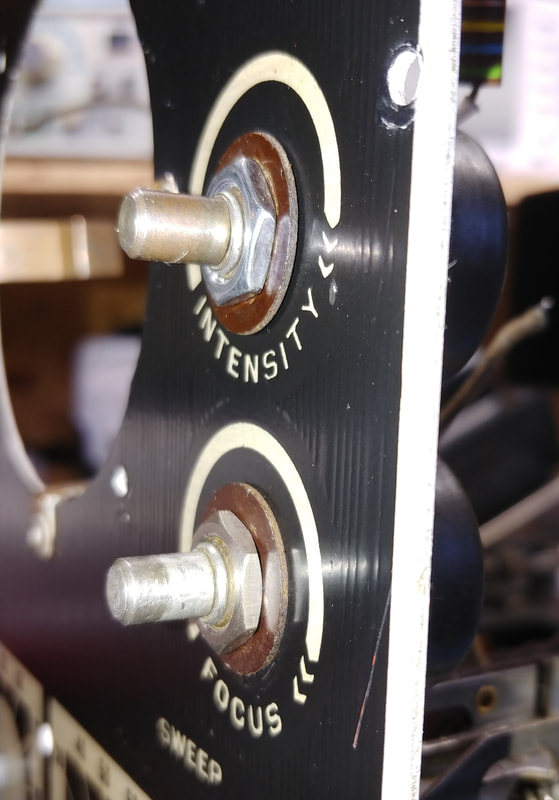
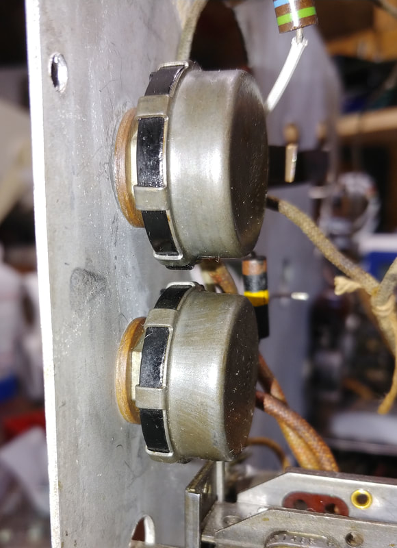
The front panel has been cleaned and polished, and the two push button switch banks pulled, restored, and reinstalled, so now I want to get the front back on quickly to lessen the chance of breaking any wires on the components that are just hanging loose without it. I added flat washers under all the potentiometer nuts to protect the front panel finish, with the exception of the Focus and Intensity pots, which are insulated from the front panel by phenolic washer sets. I also removed the internal-tooth lock washers from under the heads of the fillester head screws that attach the front panel to the chassis. The toothed washers were digging into the aluminum panel and ruining the finish around the screw holes. But there are still external-tooth washers under the nuts on the chassis side.
|
Can't do much more on the main chassis until I get the video amp reinstalled. To get started on the amp I stripped it down to the bare bones for cleaning and to make it easier to replace some of the old components. About everything except the coils and tube sockets will get replaced.
|
|
|
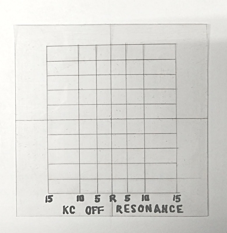
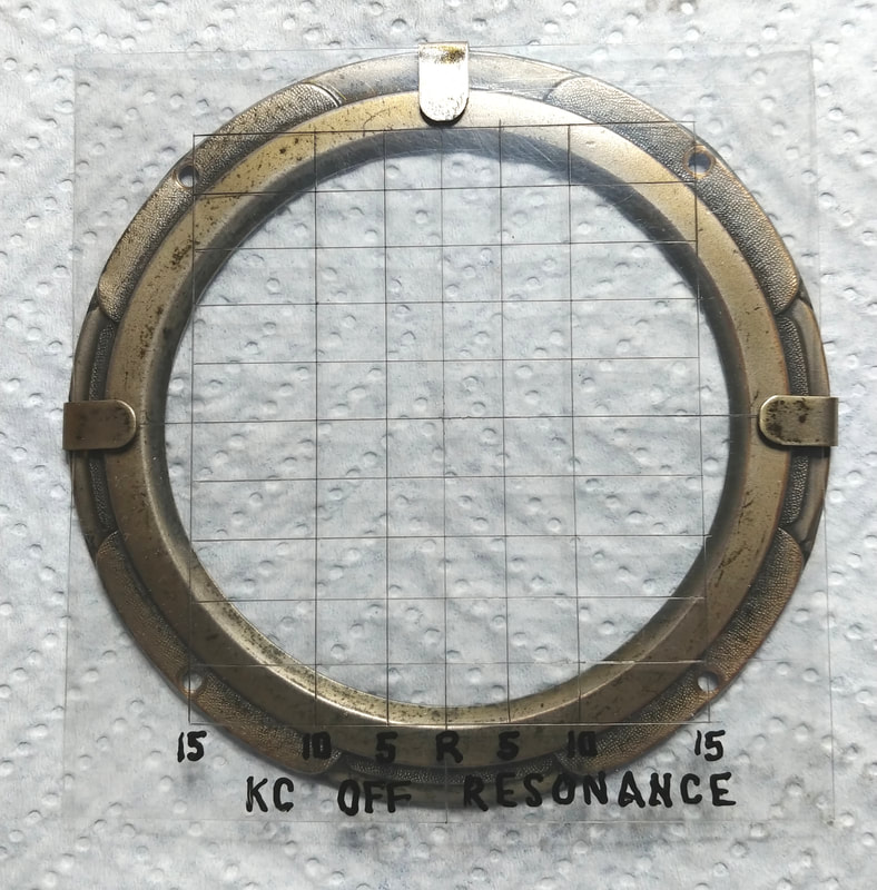
While waiting on parts I created a graticule using a scan of one from the Supreme Instruments site. The lines on this one are not printed but cut into a heavy piece of plastic with an exacto knife and then filled with a black paint pen. The lettering is also done with the paint pen. It slips under the three little ears on the front of the bezel. This particular graticule is for use with the model 561 generator in sweep mode, and one came with the 561, and also with the 560-A.
|
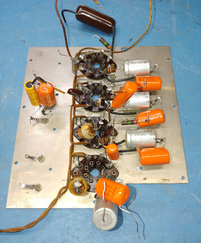
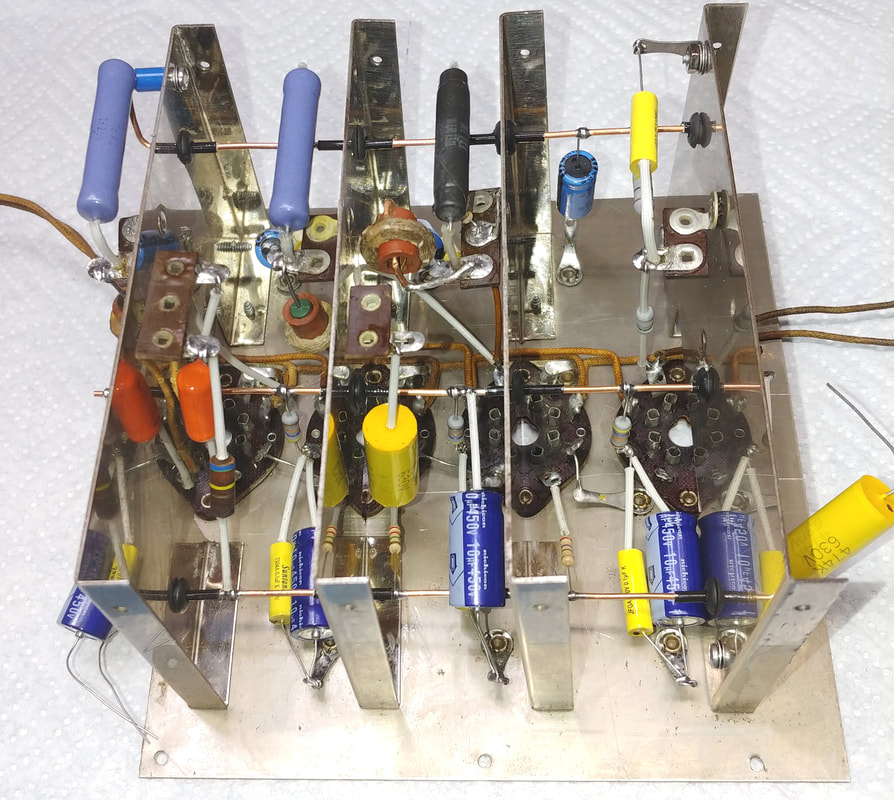
After several late nights at the bench the video amp is finally ready to reinstall. Almost every resistor and capacitor has been replaced. Some resistors were wildly out of spec, double or triple their marked values. A lot of the capacitors had already been changed once, and orange dip caps are good film caps, but I don't like their radial style leads for point-to-point wiring like in the video amp, so I replaced all but a couple with axial lead film capacitors. All the old hard-as-a-rock rubber grommets were replaced and new B+ and -Bias buses were made from 14awg solid copper wire.
Some resistors did not match the values shown on the schematic, but thanks to the poor workmanship by the mystery mangler, it was fairly easy to tell which components were from the factory just by inspecting the lead wraps and soldering. |
All the component differences I found appear to be factory. I even checked Mr. Carlson's videos to compare with his Vedolyzer and it looks like he had the same changes I found in mine. So I'm editing the schematic as I go. I've also found some components that are not on the 560-A schematic but are on the 560 schematic. More examples of design changes I guess.
|
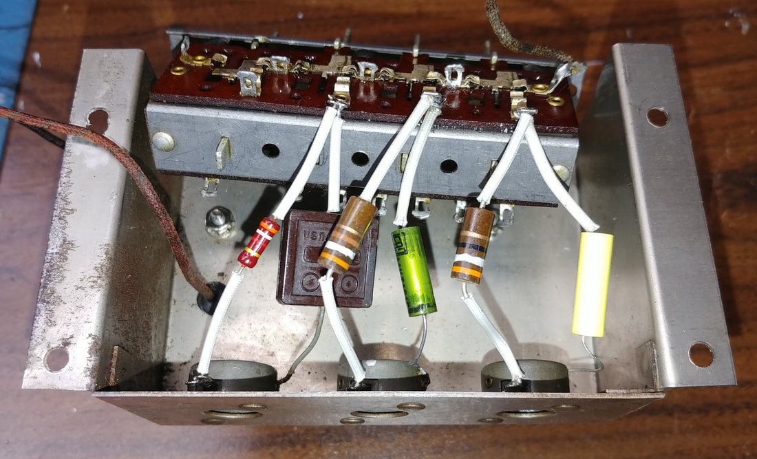
Under the Wavemeter subchassis I replaced all three resistors and two of the three capacitors (the mica was OK) that connect to the Multiplier switches. I ran into a small problem replacing the resistors, the leads on my modern film resistors are just a little too short. I had one older 1/2-watt film resistor with longer leads for the 4K ohm resistor, but had to dig through my 1-watt carbon comp resistor drawers to come up with the other two replacements.
|
|
The underside of the chassis is ready for testing. This has been a whole lot of work getting it back to this point. The three input connectors have been changed to SO-239 connectors because they are a perfect fit for the holes, and adapters to BNC are readily available. The original single pin microphone connectors are obsolete and unavailable unless you can find used ones. I'll bag the originals and keep them for the unit in case I'd ever want to put it back to factory.
All the pin jacks were replaced with a matching-style banana jack, because I like them better than pin jacks and I already have lots of cables with banana plugs. But again, I'll save the originals. |
|
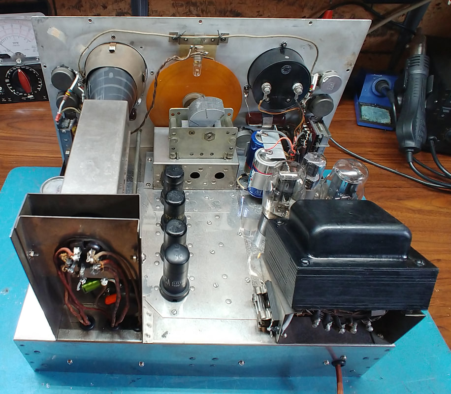
On the top side I have tested and reinstalled the tubes, and replaced a gassy 1852 tube plus swapped the 6AG7 (it tests good) for one that tests better. The 6AG7 tube socket pins were very loose, causing intermittent operation, and were tightened up. I reinstalled the CRT's plug and tested it to see if I have the pins sorted correctly. It works but the brightness is low and the focus seems off (possibly A1 and A2 are swapped), so I replaced it with a new JAN 3AP1 CRT which works fine. I'll figure out the old CRT later. I also added another battery holder on top of the chassis for the ohmmeter batteries. It holds two "D" cells and is attached to the original battery plate with thumb screws so it can be removed for easily installing new batteries.
|
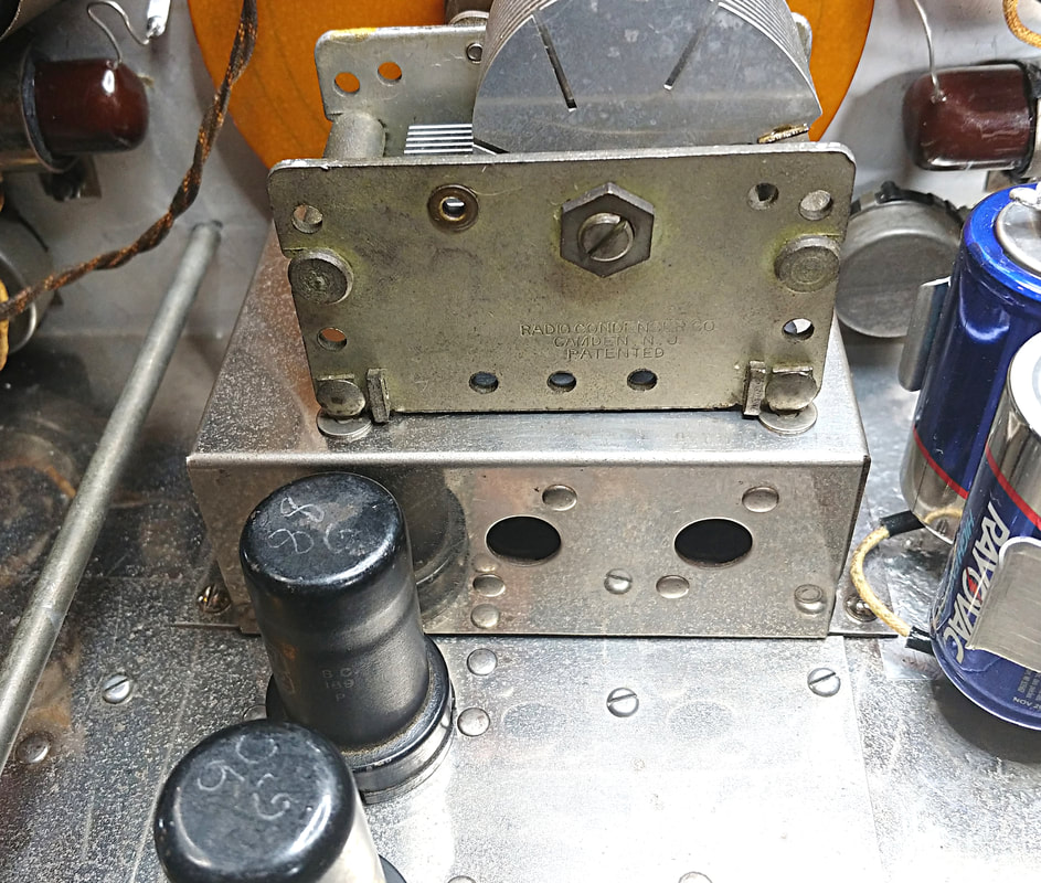
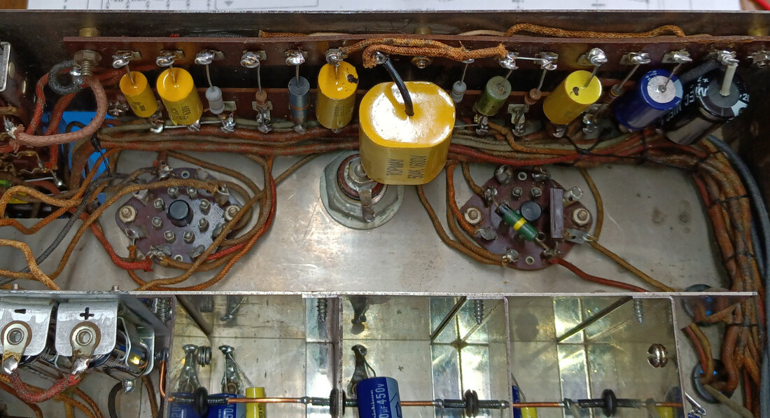
The round can capacitor mounted on top near the CRT is the 0.5uF 1500VDC filter capacitor for the CRT high voltage. It still tests good so I left it installed, at least for now. I'll have to order a replacement film capacitor for it and next time I have the Vedolyzer on the bench I'll disconnect the old cap and install the new one. I also looked it up in an old capacitor catalog and it is oil-filled with an oil that contains PCBs. So it should never be opened and should be carefully disposed of if it ever shows signs of leaking. One of the hazards of restoring vintage equipment.
The cabinet has also been repaired and refinished and is ready for the chassis as soon as testing and alignment are finished.
The cabinet has also been repaired and refinished and is ready for the chassis as soon as testing and alignment are finished.
I added a 2-cell AA battery holder for the bias batteries. This way I don't have to solder directly to them. The original battery clamp was also AA size, or whatever the equivalent was back then.
The two original power supply filter caps were in a box mounted to the rear of the chassis and had already been removed. So I made a minor wiring change to the terminal boards where the filter wiring originally tied in, so I could mount the two replacement electrolytics right to the terminal boards.
The two original power supply filter caps were in a box mounted to the rear of the chassis and had already been removed. So I made a minor wiring change to the terminal boards where the filter wiring originally tied in, so I could mount the two replacement electrolytics right to the terminal boards.
To summarize all the new parts installed to this point, I've replaced 46 resistors, 41 capacitors, 1 potentiometer, 2 1852 tubes, the dial lamp, 22 grommets, 3 input connectors, 6 pin jacks, the power cord, a broken fuse clip, most all of the hardware on the chassis, all the 3/8" front panel nuts, and added 3/8" flat washers to protect the panel's finish. I've also installed 2 battery holders and made 9 brass standoff spacers to replace missing ones for the terminal boards, and purchased fillester head screws to replace some missing ones on the front panel, 2 new handles to replace the missing ones on the cabinet, 4 new rubber feet, and all new hardware for mounting the unit in the cabinet and attaching the rear panel. And I replaced the 3AP1 CRT. I think that about covers it.
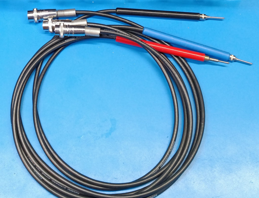
The last thing to do before starting testing is build a new set of probes. Each of the three front panel connectors has a color-coded ring that matches its mating probe's color. Red is the Video/RF probe and the schematic says it contains a 0.5pF capacitor and a 3MΩ resistor. Blue is the IF probe and has a 1.5pF series capacitor, and black is the AVC/Audio probe with a .37MΩ series resistor.
Initial testing revealed a few minor issues such as loose pins on several tube sockets, two jumpers I forgot to reinstall when replacing some resistors, and I found some more components that are only on the original 560 schematic. Another 1852 tube was either very microphonic or had an intermittent internal short and was replaced. It caused the scope trace to jump wildly just by tapping on it. Also, when focusing the CRT, the Focus control was near maximum clockwise rotation. To bring the focus point back towards the center of the control I made a small modification by changing the 100K resistor between the Focus and Intensity controls to 200K.
The B+ high voltage is about 300 - 310V depending on the function selected, and the CRT high voltage is about -1000V.
While on the subject of high voltages, a WARNING about the Vedolyzer chassis is in order. This is a dangerous chassis to work on because the component mounting strips running along the inside walls on both sides of the chassis expose hazardous voltages right along the bottom edges of the chassis, right where you could easily brush against a high voltage terminal while testing or even put a finger directly on the AC line voltage.
And there are also other exposed points with high voltage present, such as on the terminals of some of the front panel's control potentiometers. CAUTION needs to be exercised and as they say, don't try this at home. If you do, you're doing so at your own risk.
There aren't any alignment instructions available that I could find, but the schematic gives a few clues. First, there is, of course, no separate calibration for the ohm meter. It's calibrated everytime you zero it and adjust infinity.
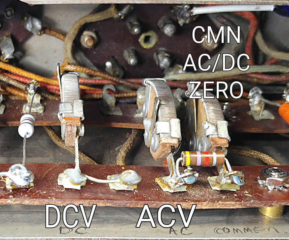
Next, the three VTVM calibrations are not labeled on the 560-A schematic, but they are on the old 560 diagram, and are the DC Cal, AC Cal, and Common AC/DC Zero adjustments. These are the three trimmers on the terminal strips under the chassis.
Before starting the calibration I set the mechanical zero of the needle. Then I set the Common AC/DC Zero trimmer to around mid range as a starting point. Not sure if I really needed to but I did. Then to calibrate the voltmeter I selected DCV and zeroed the meter with the front panel control. I selected the proper range, applied the calibration voltage, and set the DC CAL trimmer for the correct reading on the dial. Next I removed the voltage and readjusted the front panel zero and repeated the steps to refine the calibration. With that done I moved on to the AC calibration.
|
To calibrate the AC volts I set the selector to ACV, but DID NOT zero the meter using the front panel control. I left the front panel zero exactly where it was after the DC calibration. Instead I used the AC CAL trimmer to zero the meter, then applied the calibration voltage and tweaked the very same AC CAL trimmer to set the correct voltage reading. It only took a very small readjustment. Then I removed the voltage and rechecked meter zero, resetting it back to zero using the COMMON AC/DC ZERO trimmer. Rechecking the zero and retweaking the COMMON AC/DC ZERO if needed can be repeated to refine the calibration. Now when switching between DCV and ACV the needle remains on zero without needing to readjust the front panel Zero Adjust. That's it for the VTVM.
|
If the VTVM isn't calibrating then check the resistors associated with the 6J5. I had to replace all the fixed resistors because they had drifted high.
I did not replace any of the hand-picked range resistor pairs for the VTVM or ohm meter. The accuracy on different ranges was still close enough to just leave them.
I did not replace any of the hand-picked range resistor pairs for the VTVM or ohm meter. The accuracy on different ranges was still close enough to just leave them.
|
The Multiplier adjustments had all been turned full counterclockwise by someone. They are the three trimmers accessible through the holes in the rear of the Wavemeter sub chassis (one hole is behind the first 1852 tube), plus there is the trim pot soldered to the back of the dual Vertical Gain pots.
On the schematic these pots all have the same range of adjustment, but in multiples of 10. The total Multiplier resistance for the x1000 range is 40-60Ω, x100 is 400-600Ω, x10 is 4K-6KΩ, and on x1 the resistor/potentiometer combo is connected at the common output of the switches and is 40K-60KΩ (it is in common with all Multiplier positions). |
Since the center of these ranges (presumably the design point) is a multiple of 50 I preset all the controls to give a total resistance of 50Ω, 500Ω, 5KΩ, and 50KΩ as a starting point. These adjustments were made with the Vedolyzer power turned off.
Each higher attenuator position of the multiplier provides greater attenuation of the input signal, but tweaking the individual potentiometers is not having any effect on signal levels, so I left all the pots set at midrange.
The Wavemeter bands are adjusted just like aligning a radio. Starting with Band A, the coil is adjusted on the low end and the trimmer capacitor on the high end, and repeated until both were spot on. Then I moved on to the next band.
There are also a couple of trimmers in the video amp which I left at their factory settings. There's no info on them in the documentation.
|
|
|
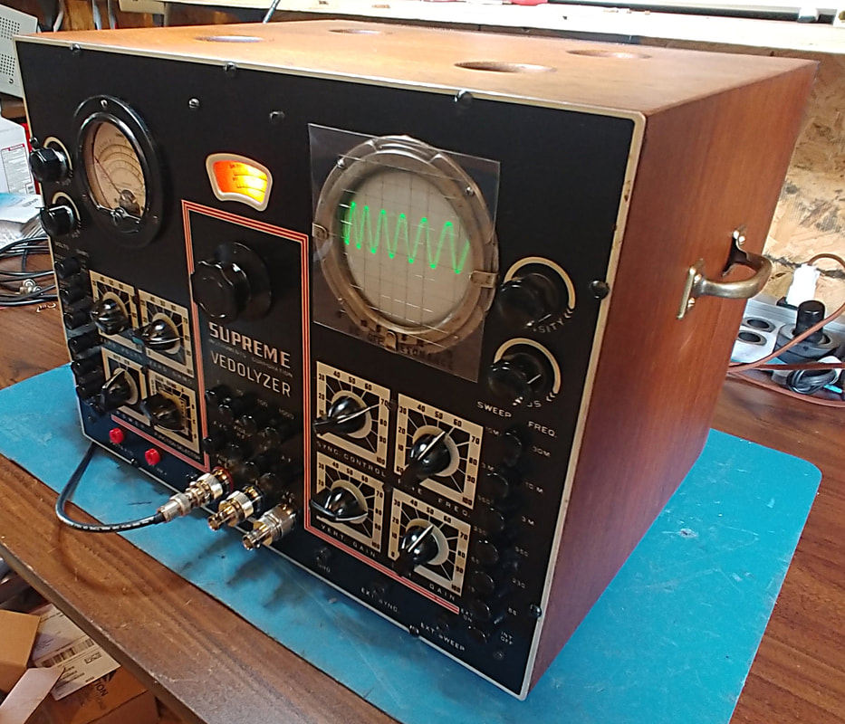
It's finally back in its cabinet and all functions are working. Learning to use the Vedolyzer is explained in the operating manual and in Supreme's more in-depth application notes for the Vedolyzer titled "See the Signal". Both can be downloaded online.
Updates to the Vedolyzer
It's been a couple of years since the original restoration of the 560-A and it still works well, but I've been wanting to put it back on the bench for a couple of updates. I'm finally at a point where the workbench is free, so it's out of its case once more.
|
The first update I'm installing is a .47uF 1600VDC film capacitor in place of the original oil-filled paper .5uF 1500VDC can in the 1000VDC high voltage circuit. The original cap is over 80 years old and it's time for it to retire. I left the can mounted on the chassis just for looks and the new cap is installed underneath. There was already a spot on the terminal board reserved just for it.
|
|
The second change I decided to make is reinstalling the original Amphenol connectors for the probes. When I found the Vedolyzer it did not come with any probes so I had no mating connectors for the three jacks. As far as I know the connectors are no longer made and the only way to replace them is to find used ones. I finally did find some online so now I can put the inputs back the way they were. If I should ever need to connect something with a BNC connector I can always make an adapter. It just looks nicer with the original jacks back in place.
|
The final items to do are checking the batteries, VTVM calibration, and the Wavemeter alignment while it's on bench. Who knows how long it might be before I get it back on the bench again. Then I'll button it up and put it back to work.
Page created 6/3/2020
Last edited 9/19/2022
Last edited 9/19/2022
