Refurbishing Two TS-323/UR VHF Frequency Meters
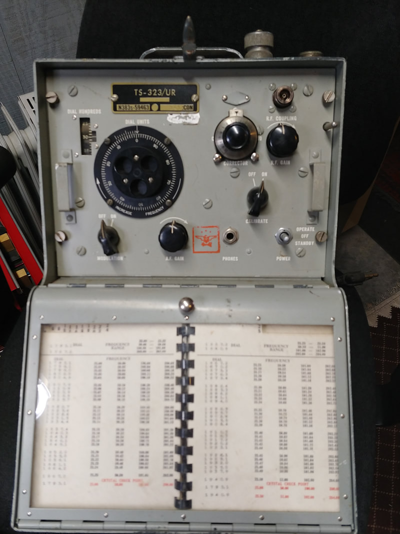
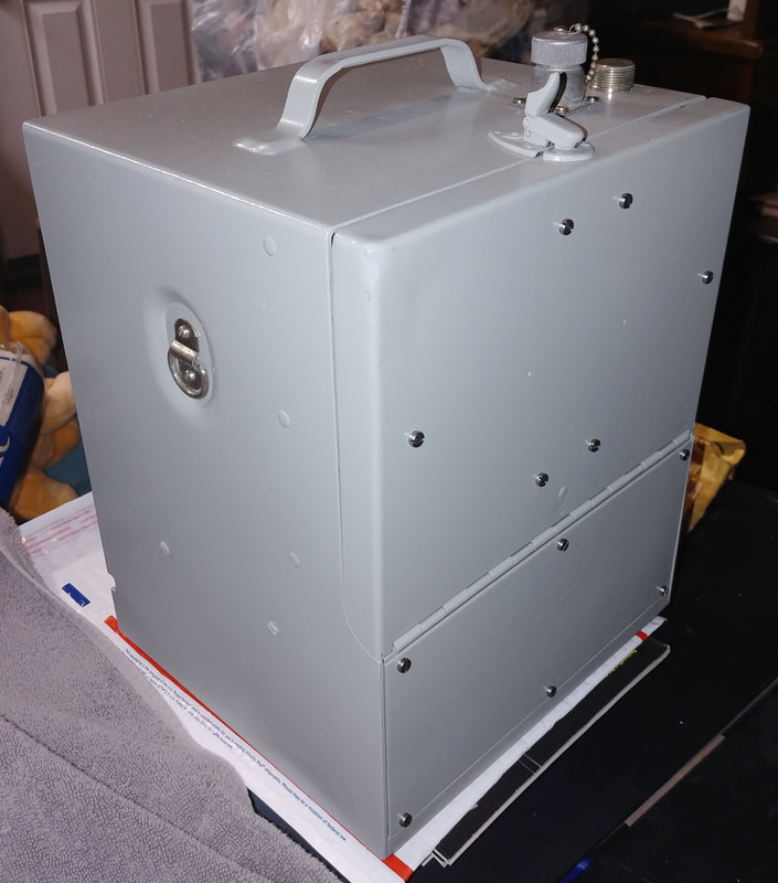
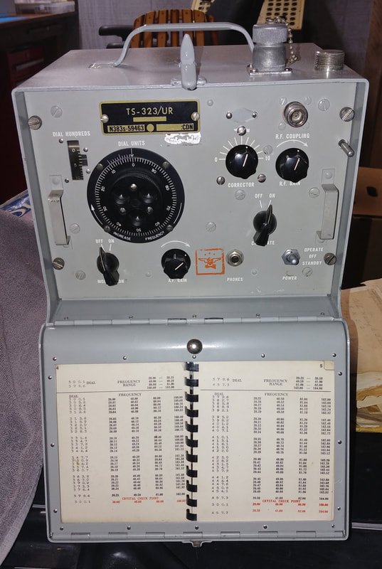
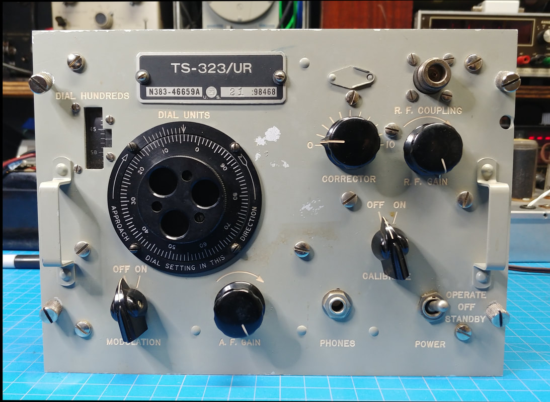
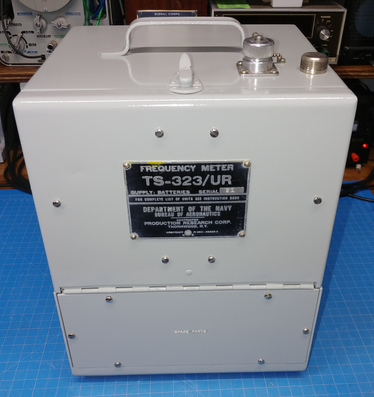
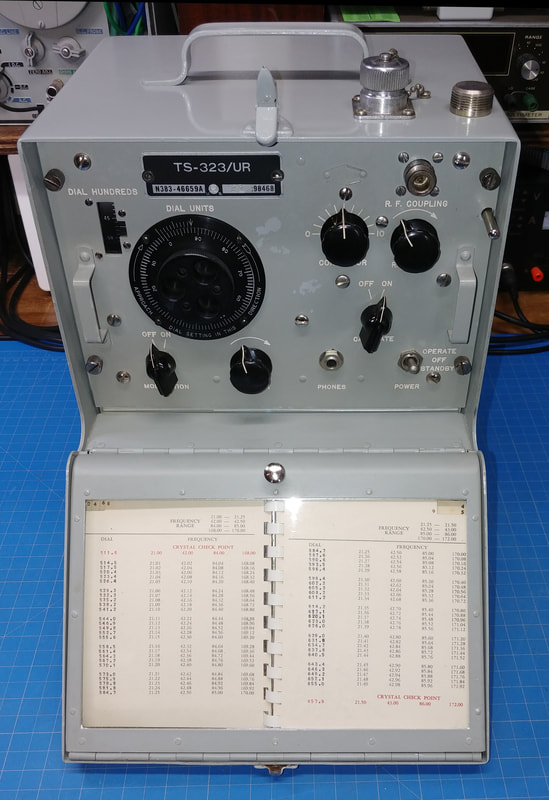
The manual says that the TS-323/UR Frequency Meter and Crystal Calibrator provides a simple, accurate and reliable means of adjusting transmitters and receivers to any desired frequency in the range of 20 MHz to 450 MHz, as well as measuring frequencies of external signals. This frequency meter is basically a VHF version of the BC-221 and just like the BC-221 it uses a matching calibration book for setting frequencies. The manual also states that under fixed bench operating conditions the heterodyne oscillator in the TS-323 is accurate to within .005% of the indicated frequency, and under service conditions it is better than .01%. The 1000 KC crystal oscillator is accurate to within .001% or 10 Hz of the specified frequency. The manual also says the TS-323 was used by the Army Air Force, the Navy, and by the British military.
|
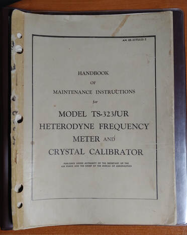
I couldn't find a downloadable PDF of the technical manual, so I bought an original one online. It's dated 5 March 1945 on the inside title page, but is actually a later publication that has been updated. The first update was September 1945 and the last update listed was January 1, 1954. I scanned the manual to a PDF file and sent a copy to the Boat Anchor Manual Archive to make it available online.
|
I bought this TS-323/UR frequency meter to use with a couple of my boat anchors and ordered it from a military surplus dealer that I've dealt with since the 1970's, but they mistakenly sent me a meter that had been hacked up by someone. They replaced it with new parts after I contacted them, but it's been kind of a comedy of errors.
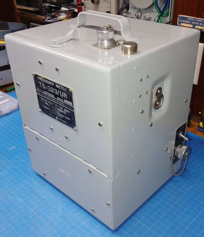
In the first meter someone removed the corrector knob, cut off the corrector capacitor's shaft behind the front panel, and mounted a vernier control by drilling two new holes in the faceplate. And the name plate on the cabinet was missing and J105 had been removed so the power cord from a homebrew internal power supply could be brought out. Not exactly an original meter.
In the first meter someone removed the corrector knob, cut off the corrector capacitor's shaft behind the front panel, and mounted a vernier control by drilling two new holes in the faceplate. And the name plate on the cabinet was missing and J105 had been removed so the power cord from a homebrew internal power supply could be brought out. Not exactly an original meter.
Restoring the Hacked Up Meter
|
To fix the problems with the first meter they sent me a second meter (minus three knobs that the first meter has), the matching book and the matching nameplate for me to install in the cabinet of the first meter. This was to save on shipping costs of sending a second cabinet. Sounds good but after restoring the cabinet I discovered I couldn't get the mounting screws in. It's covered further down the page.
|
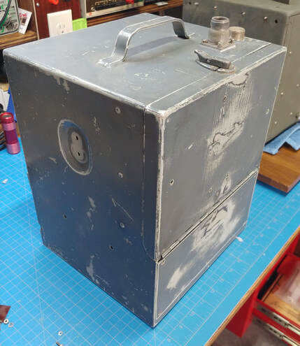
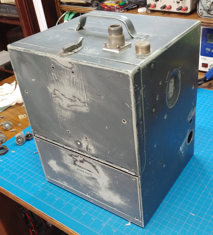
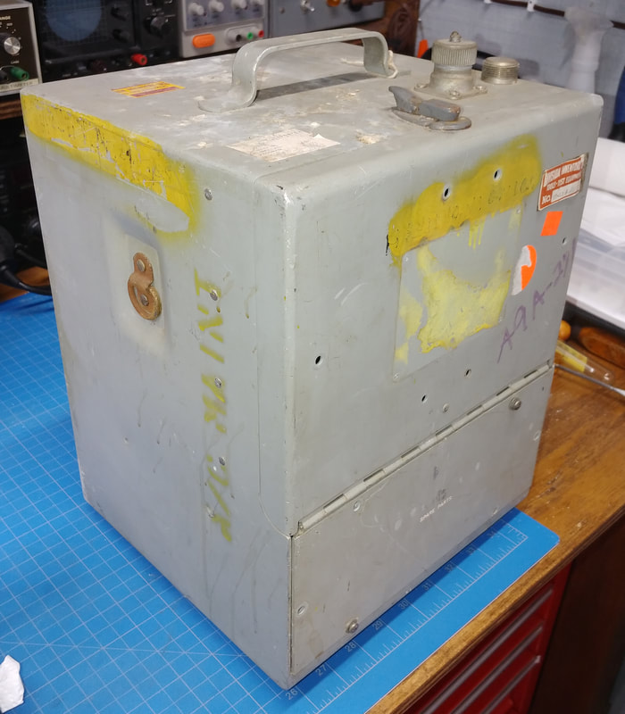
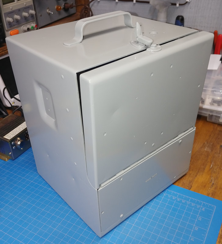
The case had been repainted dark gray, but it's really scratched up now, so I'm sanding it a bit to remove as many of the scratches as I can before giving it a new paint job in the original light gray color.
I've been using Rustoleum Professional Gloss Light Machine Gray as it's the closest color match that I've found in an off-the-shelf spray paint. It might not be exact but it's close enough. And since this old military equipment is dirty and been exposed to the elements over the years, it's probably not exactly the same color it started out as anyway.
I've been using Rustoleum Professional Gloss Light Machine Gray as it's the closest color match that I've found in an off-the-shelf spray paint. It might not be exact but it's close enough. And since this old military equipment is dirty and been exposed to the elements over the years, it's probably not exactly the same color it started out as anyway.
|
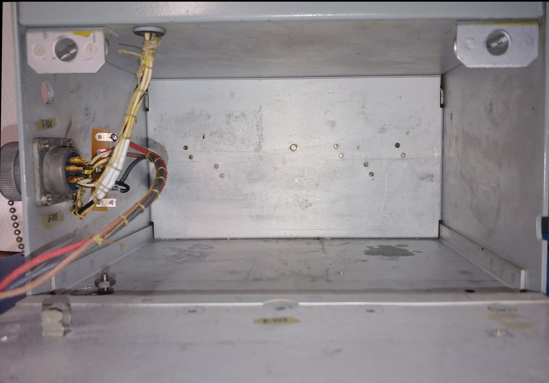
I'm happy the meter came with a power supply installed, but wish someone hadn't removed the connector, the external power switch and the label plate while installing it, just to bring out the power cord. All that was needed for the cord was just to leave the lower compartment door slightly open, or use the notch someone had already filed in the cabinet door edge for a power cord, duh! Instead, the wiring to the external power connector J-105 and Ext. Power switch S-104 was cut off, taking the battery plugs with them when they were removed. So the power wiring needs sorted and repaired along with replacing the label plate and dust cover for the connector, if I can find them.
|
|
There's really no use in adding the battery plugs back, no one is going to put batteries in this, but I put the J-105 connector back for originality and added a terminal strip next to it to tie in the internal power supply as the new "batteries", instead of wiring it to S-104. Then I can use S-104 as the On/Off switch for the internal supply.
|
|
After refinishing the cabinet, rebuilding the power supply, and restoring the new replacement meter, I slid it into the cabinet for testing, and guess what, the mounting screw holes don't line up. They're off just enough that I can't get the screws to thread into the mating holes. Tolerance variations between different manufacturers I guess. After a good laugh, and convincing myself it just wasn't going to fit, I contacted the seller again and arranged to get the replacement meter's original cabinet shipped to me. So much for saving a few bucks on shipping.
|
|
While waiting on the replacement cabinet I decided I might as well repair the hacked up meter, since I have already restored its cabinet. So I removed the vernier and made a shaft coupler out of brass tubing to extend the cutoff shaft and reinstall a knob. When I get time I will make a nice aluminum shaft coupler on my lathe. I also plugged the two extra holes in the face with matching screws. The three round knobs are not originals but are of a similar style. All that's left is checking for leaky caps and out of spec resistors. It's not the one I was intending to restore but it's almost done so I might as well finish it up rather than scrapping it. Then I can get on with restoring the good one.
|
Restoring the Replacement TS-323
|
|
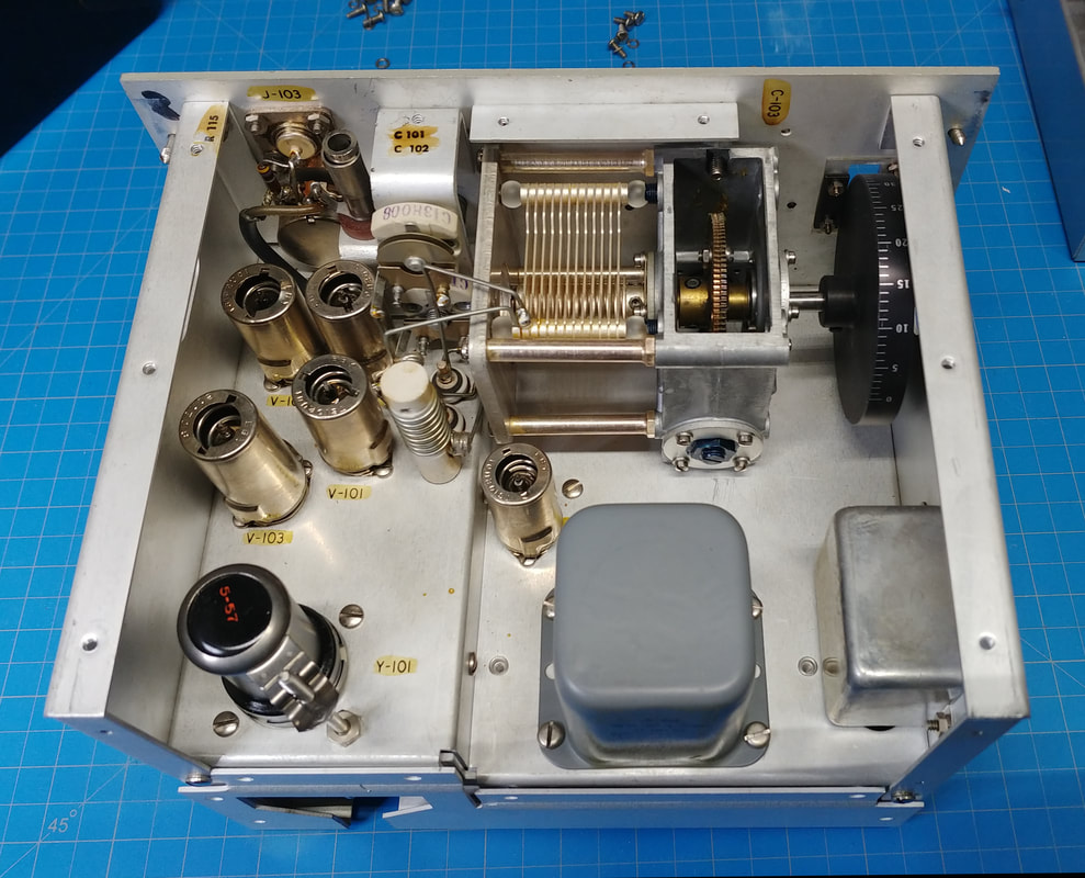
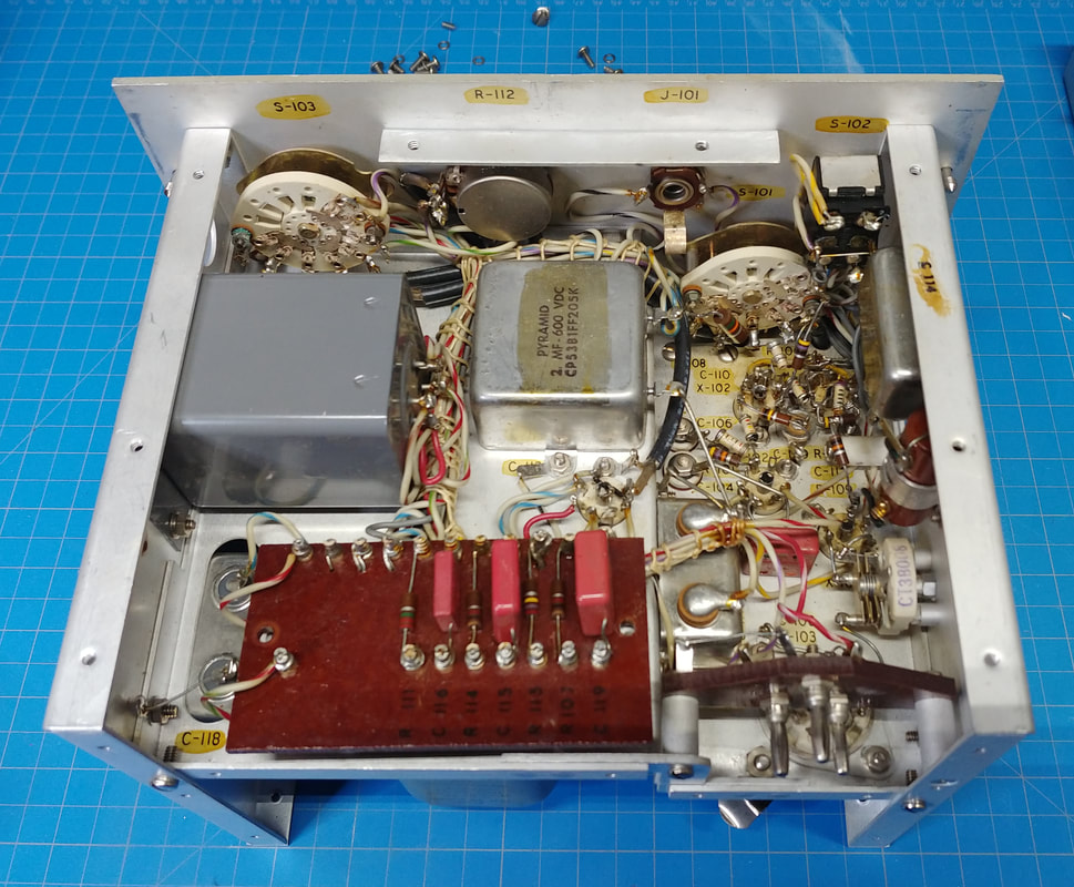
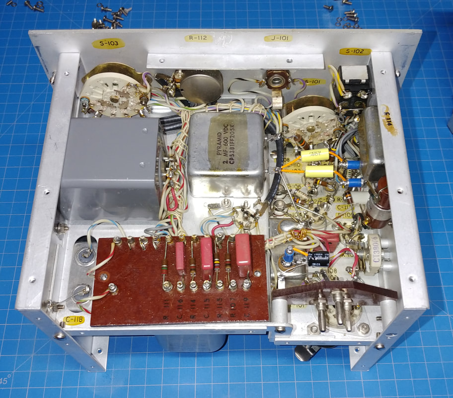
The two 0.1uf 600V caps in the bathtub C-114 both showed almost no leakage with the ohmmeter on the X100,000 range, less than one division off of Infinity. But on the Heathkit capacitor tester it was a different story. One failed at 100V and the other at 150V. They were replaced using turret standoffs soldered onto the old terminals, because their bathtub is full of oil, and I don't want to open it.
The two large 2uf 600V capacitors, C-113 and C-118, were a surprise. Both are listed as paper in oil in the parts list but show no leakage and test great on the IT-28 at 600V, so maybe they are difilm caps. Anyway, they can stay. The one electrolytic capacitor, C-117, was replaced due to its age. A turret standoff was also used to install its replacement. Normally I would have put the replacement inside the bathtub since electrolytics aren't oil filled, but getting to the screws to get it out just wasn't worth the effort required (Looks like I'd have to remove a tube socket just to get to one of the screws). |
Refinishing the cabinet is done for the good meter and all that's left to do is finish altering the wiring in the battery compartment for the new power supply I'm building for it.
The paint on this meter is a different shade of gray from the previous military sets I refinished. I went ahead and touched up the missing paint but it's not a great match. This meter's paint has a brownish tint so I need to see what I can find at the paint store.
Rebuilding the Homebrew Power Supply
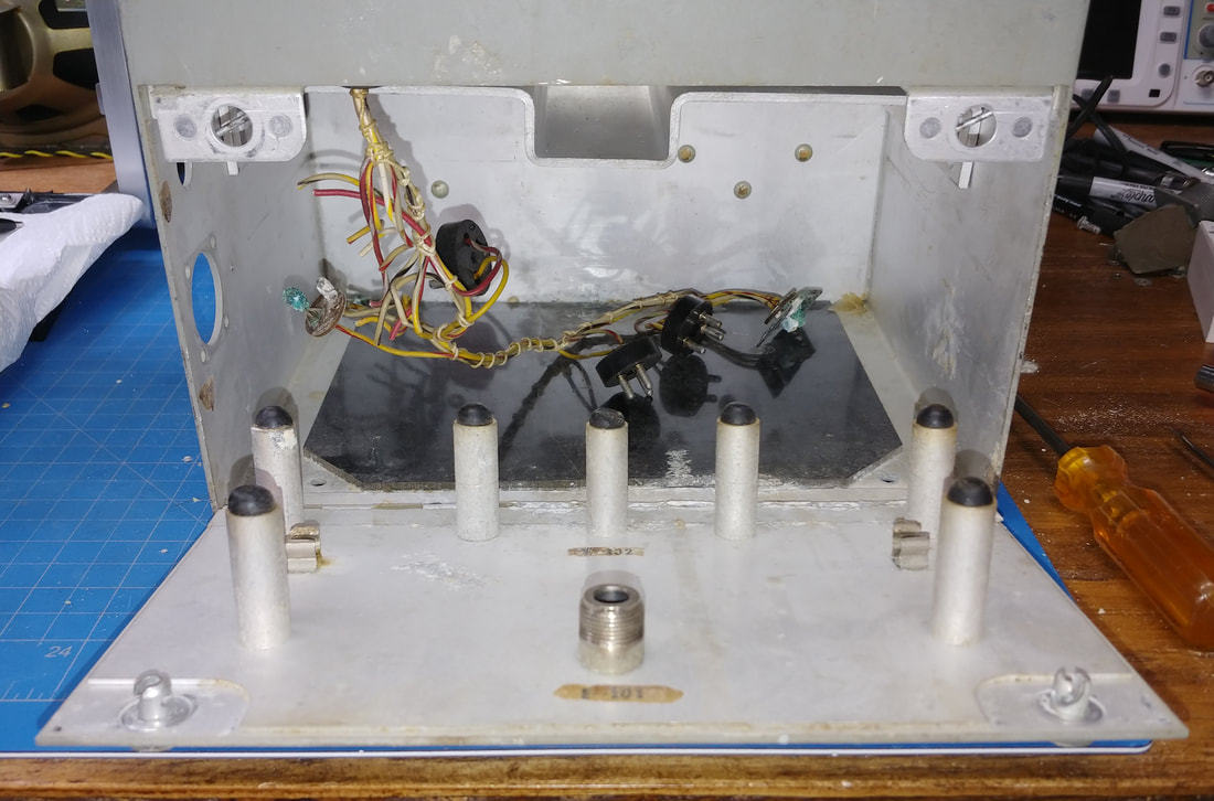
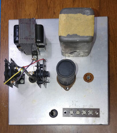
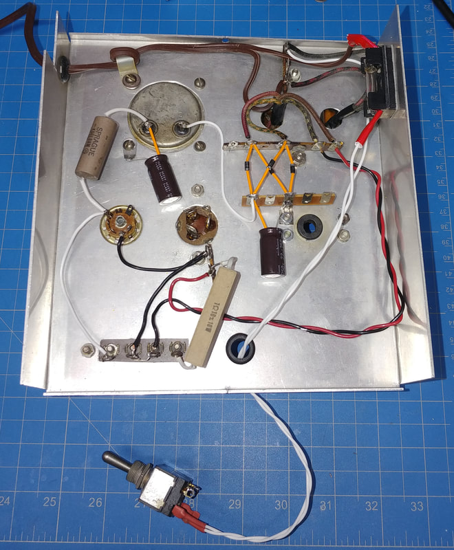
The first unit came with a homemade power supply to replace the batteries, but it needs rebuilt too. I wanted to reuse this power supply in the good meter, but oddly it won't fit in the cabinet, because there is a bakelite panel riveted in the bottom that raises the supply just high enough that its chassis hits some rivet heads on the back wall of the compartment, and that keeps it from going in far enough to shut the rear door. The bakelite panel has been removed from the other meter's cabinet which is why it fits in it. I don't want to remove the bakelite panel from the new cabinet so it looks like I'll need to build a new supply.
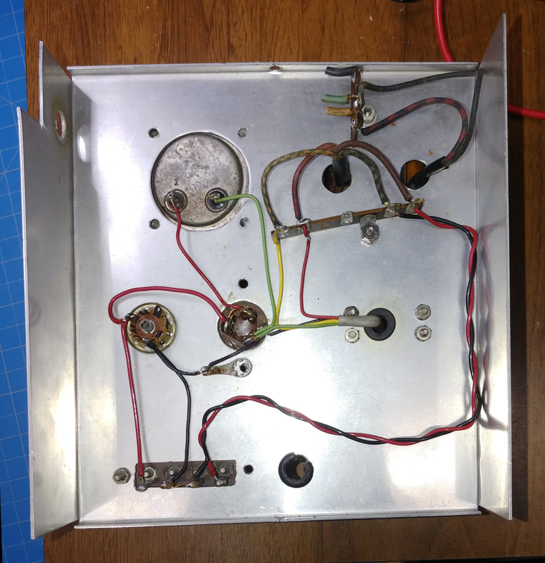
The bottom of the filter can is bulging and has leaked electrolyte, and there was a low ohm short to ground at the wiring to the choke terminals, but after removing the choke and capacitor it disappeared. Neither component checks as shorted so now I'm not sure where the short was. The rectifier diodes still check good, but are so old I can't find a data sheet. There's two diodes on each stack and together the two stacks form a full-wave rectifier. There was also a voltage regulator tube that's missing, but whoever built this didn't add the series current limiting resistor for the tube, so it had to be working overtime. I think I'm just going to strip the whole thing and start over.
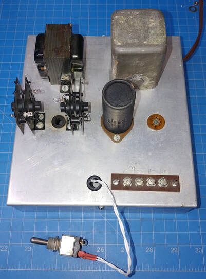
I replaced all the solid wiring with stranded teflon except on the 6.3VAC filament lines, added a fuse in the transformer primary, and wired the meter's original Battery/External Power switch as the AC On/Off switch (the battery plugs and wiring to the switch had already been cut off). I also replaced the bad filter caps, but left the old can installed so there wouldn't be an empty hole in the chassis. And I left the original rectifier diodes on top, but installed new diodes for a full-wave rectifier on terminal strips underneath.
The unregulated DC at the output of the choke is about 190V, so my plan was to install an 0A2 regulator tube in the tube socket to provide regulated +150VDC out. I also rewired the tube socket so that if the tube is pulled there won't be any B+ output. As originally wired, if the tube was pulled the full unregulated B+ appeared at the output. And I added the missing current limiting resistor for the 0A2.
But it was all to no avail. The power transformer is a very small unit and the high voltage winding is good for around 23ma at 185V, which is the minimum voltage for the 0A2, but the meter and tube together draw about 27 - 28ma. This is pulling the unregulated B+ down and it's not enough to keep the tube glowng. Long story short, I either need a better transformer or just run it unregulated. The latter is cheaper so I pulled the tube and added a 2000Ω resistor in series to drop the voltage to approximately 140V. Close enough.
Lastly, the filament voltage out of the power supply was at 7.1VAC with the frequency meter connected, so I added a 1Ω resistor in series with the output, which lowered the voltage to 6.25VAC. This power supply will go back in the first meter. I'll build a similar power supply to fit in the set I'm keeping.
Page created 11/5/2020
Last Edit 12/9/2020
Last Edit 12/9/2020

