Restoring a TS-505D/U Vacuum Tube Voltmeter
This TS-505 "D" model dates to around 1958. It's a ruggedized vacuum tube voltmeter that can measure DC voltages from .05V to 1000V, AC voltages from .05V to 250V at frequencies from 30Hz to 1MHz, and resistance from 1 to 1000MΩ (1GΩ). And using the MX-1797/U RF adapter on the DC probe, it can measure voltages from .05V to 40V at frequencies from 500KHz to 500MHz.
The D model is arguably the best model of the TS-505. It is the only version that doesn't pose a shock hazard when measuring higher voltages. This is because it has an isolated common that is not connected to the metal body of the meter, unlike the other four versions.
I picked up my first TS-505D back in the '70's, but don't have it anymore, so when I saw this one for sale, nostalgia took over and here it is on the bench.
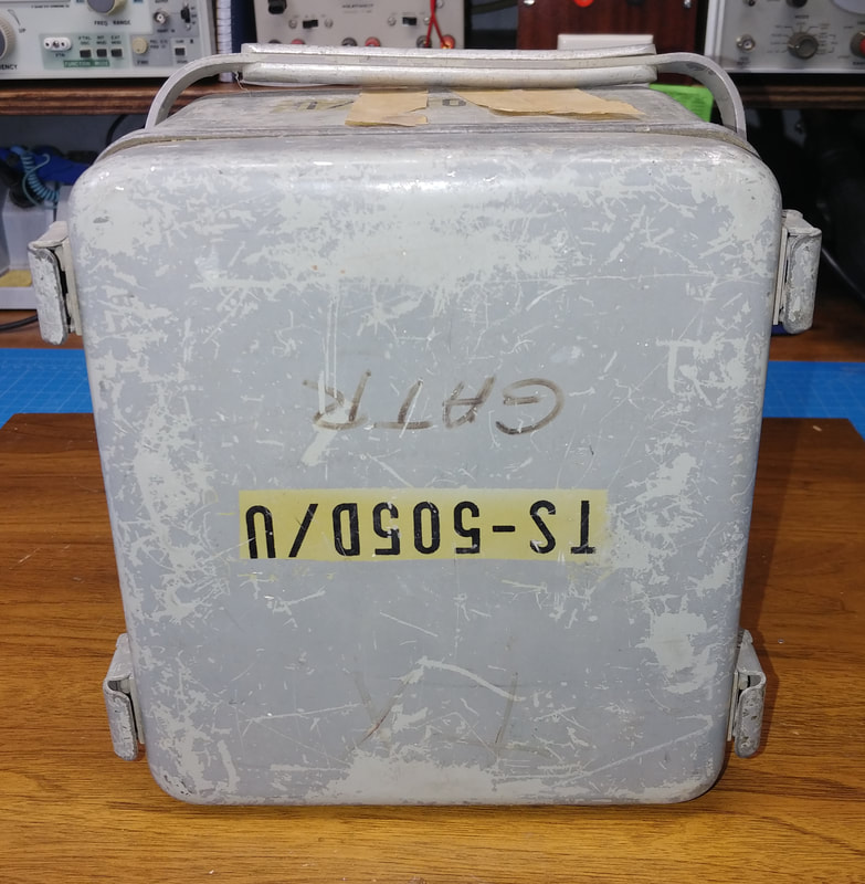
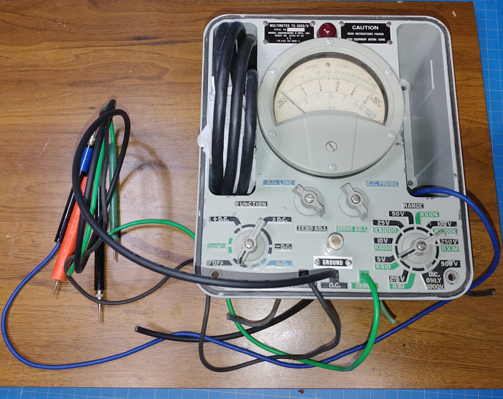
On the outside this one is a bit rough, but with a good cleaning and a new paint job it won't look like the same instrument.
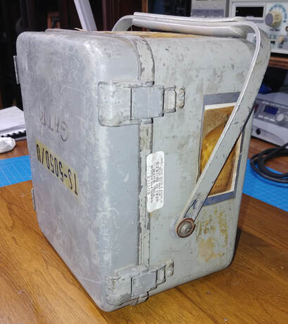
The handle is bent and some of its mounting hardware is missing. The meter is sitting upside down in the photo because the handle is stuck around the bottom. This will all get fixed when the case is disassembled for painting.
The handle is bent and some of its mounting hardware is missing. The meter is sitting upside down in the photo because the handle is stuck around the bottom. This will all get fixed when the case is disassembled for painting.
|
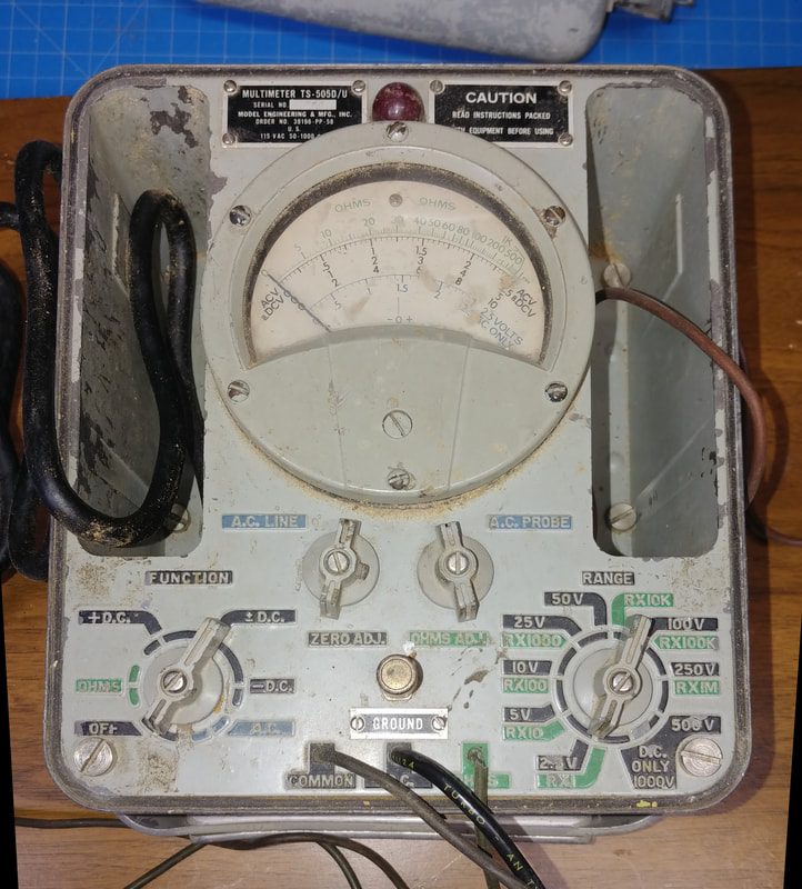
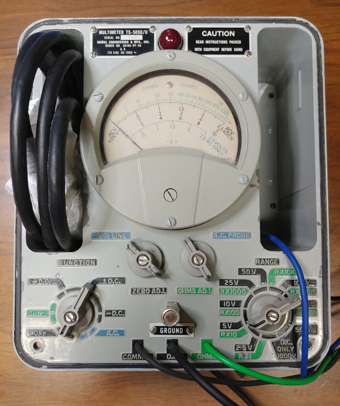
The face is dirty and there's paint chipped off around the storage compartments on each side of the meter movement. All the probes are there except the one for ACV. When I bought this I thought there was mold growing on the rubber gaskets, but it turned out to be sawdust of all things.
The insulation is cracked on the black and green test leads and there's bare wire where they enter the meter, so I'll be installing all new leads. The shielded cable for the DCV probe is stiff and needs replaced. Also, the power cord is so stiff it cracks just trying to unfold it, so it will have to be replaced. The storage compartments are scratched and dirty and will need repainted in addition to touching up the chipped edges. |
|
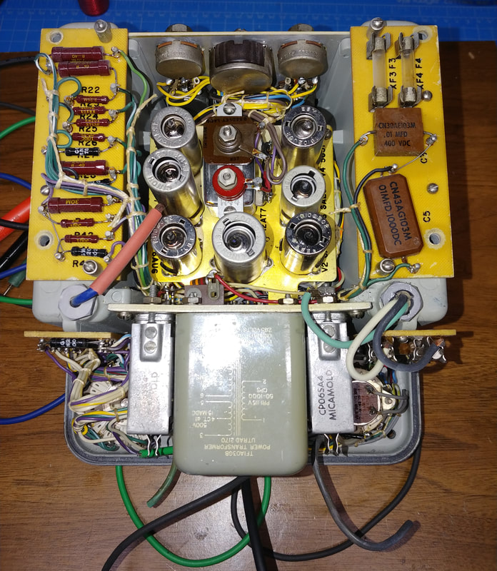
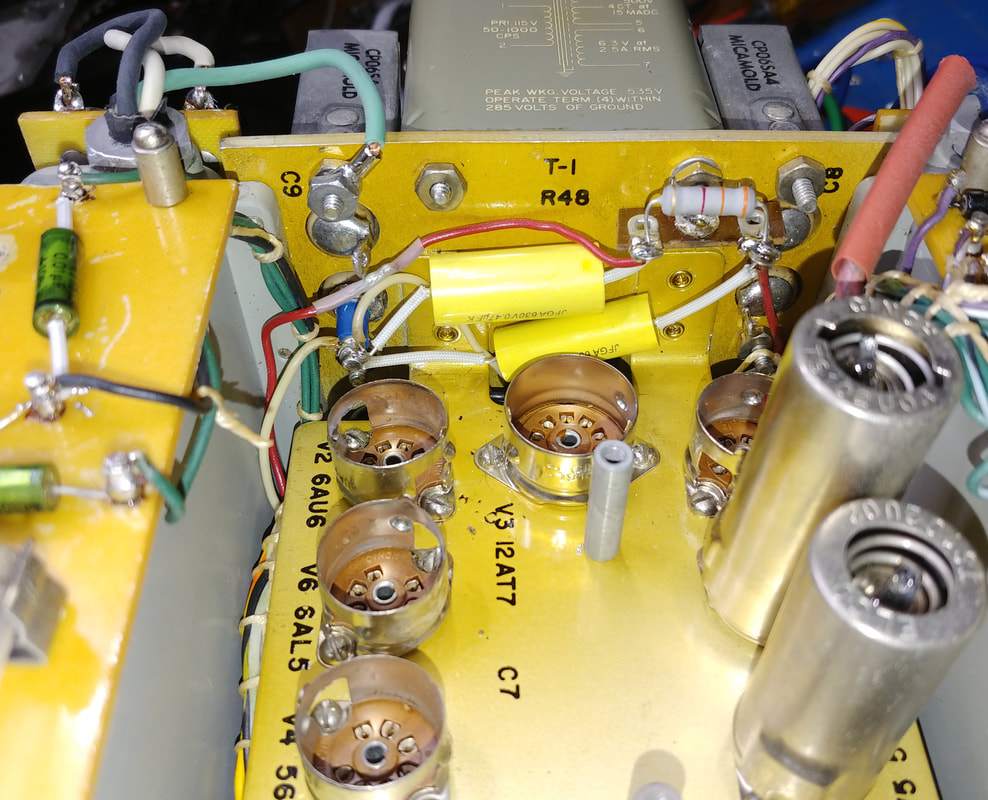
The electronics are clean thanks to the sealed case. A few of the tube shields had a little oxidation that cleaned off easily, and there was some white rust on a couple of zinc plated parts. But that brushed off easily too.
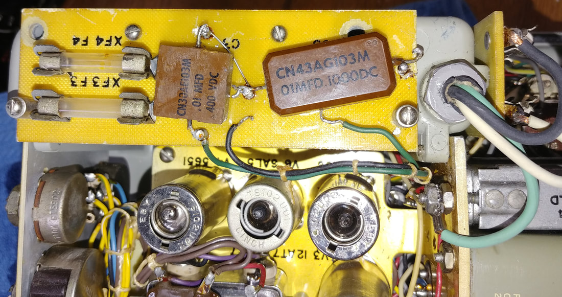
I see several .01uf micamold-style capacitors that I'll need to check to see if they are paper. And I want to check the two 0.5uf filter caps to see what they're made of, too. |
|
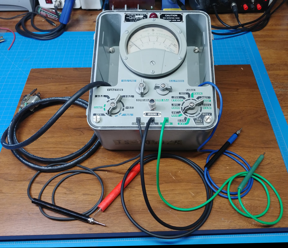
The face has been repainted from the top down to the center line of the meter movement. The two compartments either side of the meter have also been repainted. The meter bezel and the rest of the panel below it have been cleaned, but still need the paint touched up.
A new line cord has been installed and I'm just getting started replacing the test leads. |
|
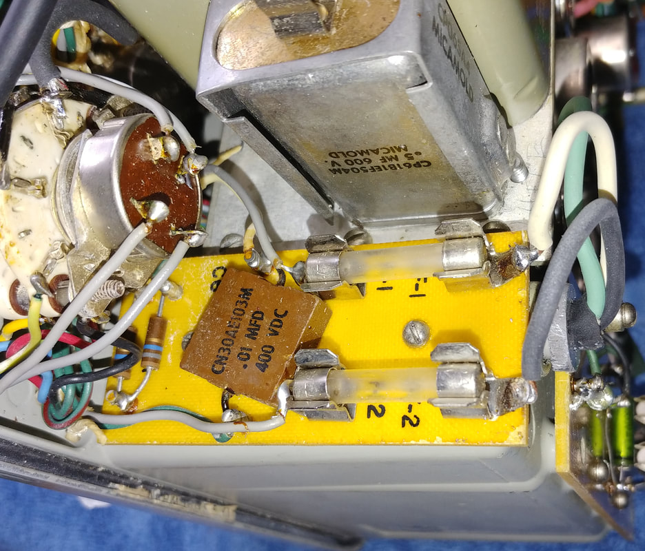
Here's another of the Micamold .01uf caps and it's bad too. And the big, rectangular can behind it is one of the two 0.5uf power supply filter capacitors. They have a 1958 date code and both of these are very leaky too, and failed the leakage test on my IT-28 at 3 Volts. That pretty much makes them a short. Good thing I didn't power up the meter before testing them.
|
|
There's not much room for replacements, but I found just enough space to mount the new 0.5uf caps against the side wall and still leave the original caps installed for originality. They are oil-filled caps and might contain PCBs, so I'm not opening them to install the new caps inside.
I changed the terminal strip to get an extra mounting lug and I soldered an insulated turret terminal to one of the old 0.5uf capacitor lugs to get another mounting point. Since I pulled the 3300Ω resistor when I removed the old terminal strip, I went ahead and replaced it with a new metal film resistor, even though it was still in spec. |
|
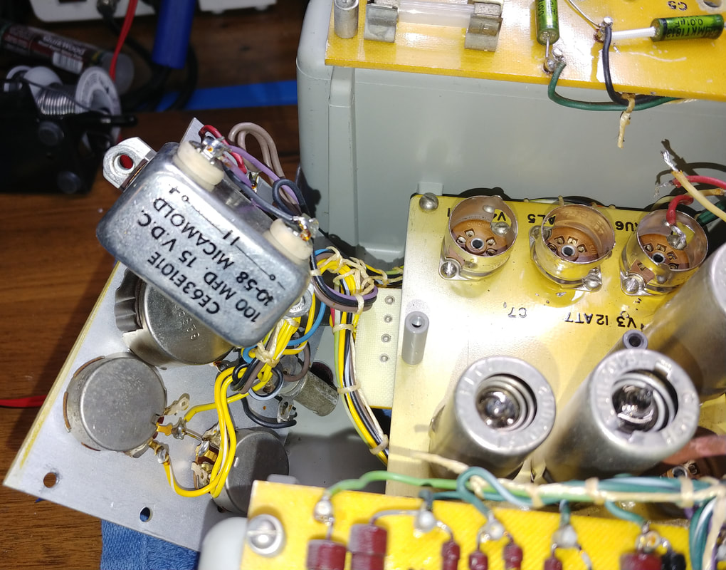
I think this is the last capacitor to replace. It's a 100uf 15 volt electrolytic. It's right in the middle of the chassis with a resistor and a selenium rectifier mounted on top of it. Somewhere I read a comment about the TS-505 meters not having any electrolytics in them, but it ain't so. At least there's one in the D model. Since this bathtub cap isn't oil filled, I cut the back open, replaced the capacitor inside, and then soldered it shut again. Normally I wouldn't solder the can closed again, but it mounts upside down so the open bottom was visible.
|
After replacing the capacitors I brought the meter up on my variac, but it was completely dead. After a big "uh-oh" I made a couple quick checks with an ohmmeter and it turned out the On/Off switch contacts were dirty. The switch was pulled and cleaned with Deoxit and now it works. Initial tests look good so next is a calibration.
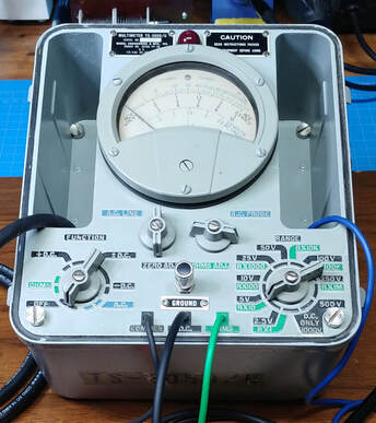
The front panel painting and touchup is done. In addition to touching up the gray paint, some of the black and green labeling needed fixed, too. It looks pretty good now.
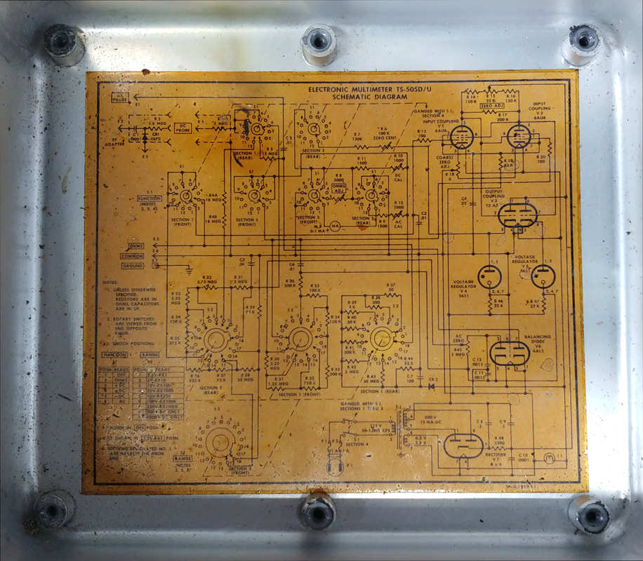
The calibration went smoothly, straight by the manual, with one exception. When I calibrated the AC, the cal potentiometer was at its minimum. On the schematic the AC Cal pot is shown in series with a 500Ω resistor R9. But R9 in this unit is 1500Ω and it's listed as the same in the parts list. I changed R9 to 500Ω, but all that did was put the cal pot at maximum resistance, so I put it back to 1500Ω. The depot manual advises to check the range resistors R21 - R27 & R29. They were all on the high side of their nominal values, but were still within 1%. I guess all the resistors being a little high has resulted in enough of a cumulative error to shift the cal pot all the way to the end.
To get the cal pot to the center of its range, the pot and R9 need to have a combined range of 1KΩ to 2KΩ. To get this range I paralleled R9 with a 2200Ω resistor. Now the AC calibrates with the pot about in the center.
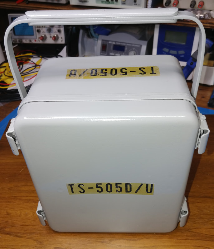
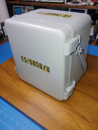
The case is now all cleaned up and repainted. I masked off the original stenciling and saved it. I used nylon washers, and plastic washers that I made, to replace the missing pieces for attaching the handle.
All the meter ranges are pretty spot on. I especially like the RX1M scale, it will be useful for leakage testing, and the ohmmeter reads accurately all across the scale.
All the meter ranges are pretty spot on. I especially like the RX1M scale, it will be useful for leakage testing, and the ohmmeter reads accurately all across the scale.
Page created 10/25/2020
Last edit 10/31/2020
Last edit 10/31/2020

