Simpson Model 480 Genescope Restoration
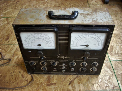
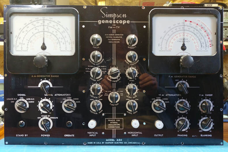
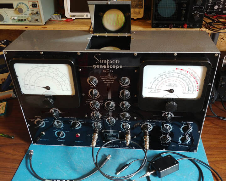
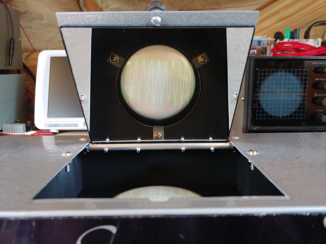
The Genescope model 480 integrates an AM signal generator, an FM sweep generator, and a 3-inch oscilloscope into a single FM radio and TV service instrument. It also includes a crystal calibrator and 400Hz audio oscillator in the AM generator. Built in the early 1950's, when most oscilloscopes took up a lot bench space, Simpson cleverly mounted the oscilloscope CRT vertically and used a flip-up door with a mirror to view the screen. This makes the Genescope cabinet only 6-inches deep, (not including the knobs) giving it a slender footprint on the workbench.
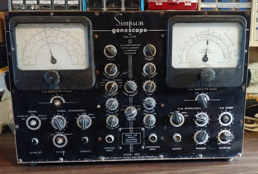
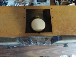
I'm going to do a full restoration of this Genescope. It's not in great condition and needs a lot of work. Plus it's missing some parts including the top door and door mounting hardware, the mirror used for viewing the o'scope, four front panel knobs, and possibly a graticule for the CRT, if it had one. But on the plus side the front panel should clean up nicely, the CRT doesn't appear to have any burn-in, and it's electrically complete. It does show signs of having been worked on in the past - a couple of capacitors were left hanging loose - but at least it wasn't totally hacked up.
The complete restoration will probably take a while due to limited time to work on it, and the amount of work it needs. On a side note, I subscribe to Mr. Carlson's Lab on Patreon and he has a Genescope he plans to restore. He does excellent work and it will be very interesting to see how he goes about it and how he mods it. I've gleaned some good tips for restoring mine from his preview video and also his Supreme Vedolyzer restoration videos (an instrument of similar complexity to the Genescope).
|
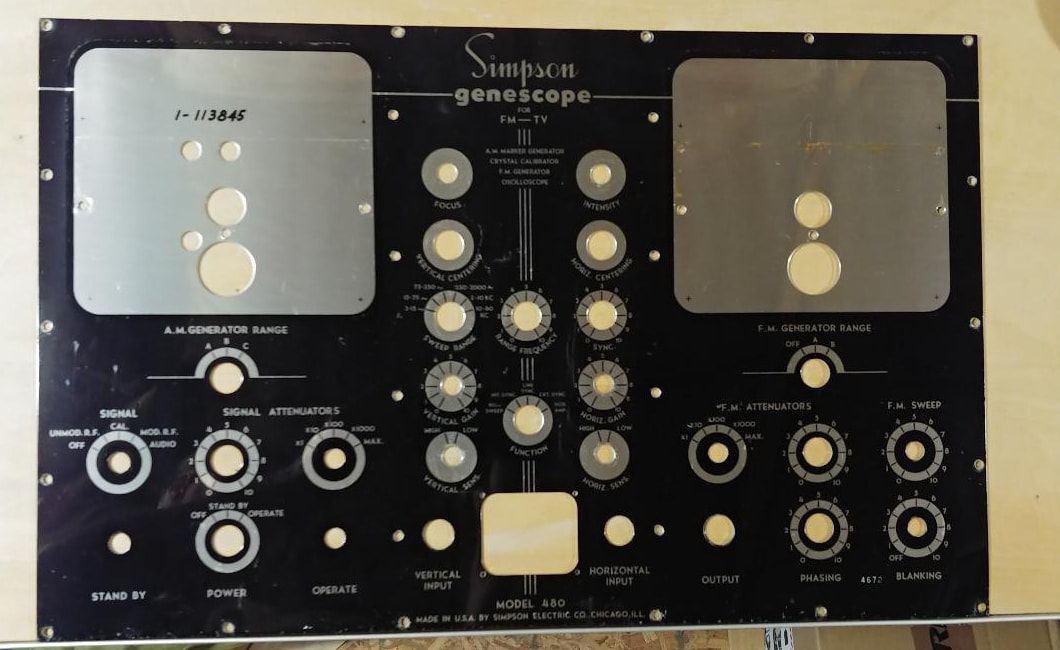
Front panel of the Genescope. Several missing knobs and noticeable scratches near the power switch and the Vertical Centering knob but no rust or peeling paint, mainly because the panel is aluminum.
During the restoration I'll remove the front panel to clean and polish it. Let's see, I've already removed 26 panel screws, so that leaves only 23 knobs, 3 connectors, 2 dials, 2 panel lamps... |
On top is the exposed CRT, where the missing door and mirror should be. If there was a CRT graticule then it has also flown the coop. At least the hard to find 3KP1 CRT is still there.
I've already cut a new door and mirror so just need to finish the mounting brackets and shaft. |
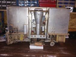
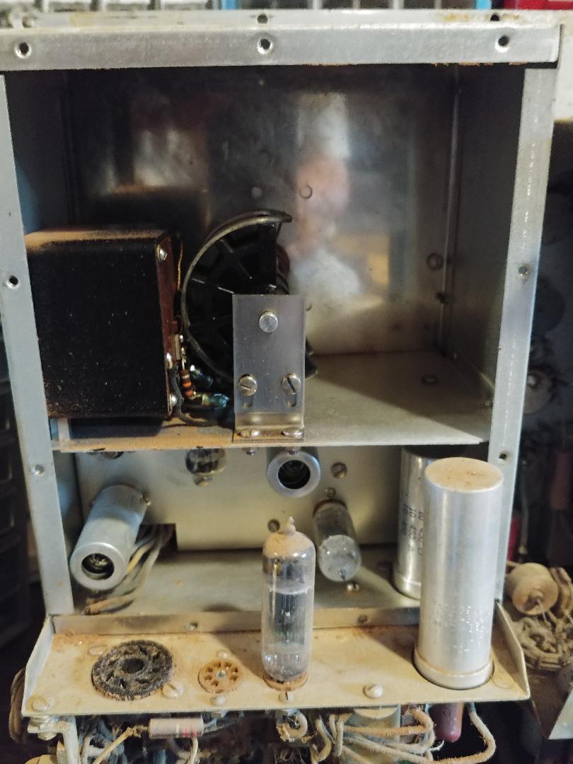
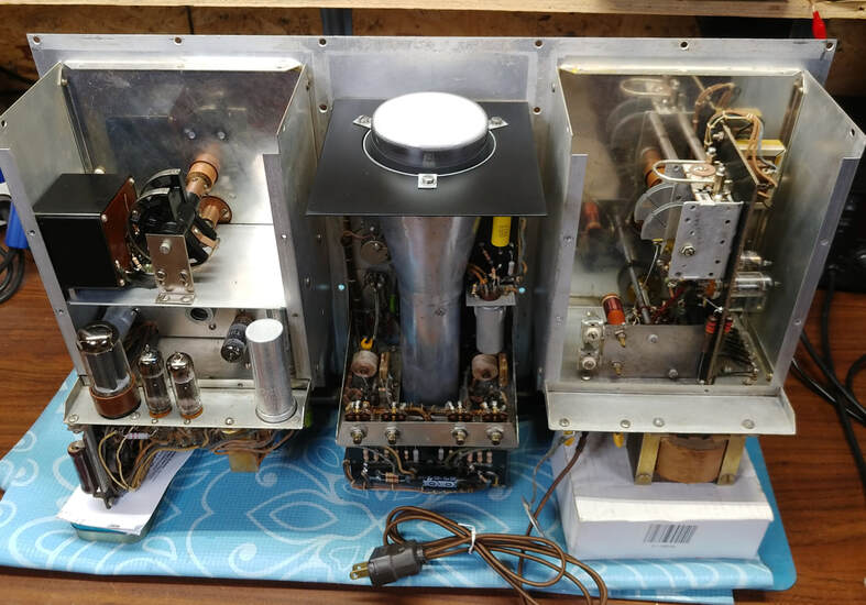
Inside there are three sub-chassis, or sub panels as Simpson calls them, the AM generator, FM generator and oscilloscope, all mounted to the front panel. The power supply components are mounted to the underside of the sub panels.
|
Restoring the Cabinet
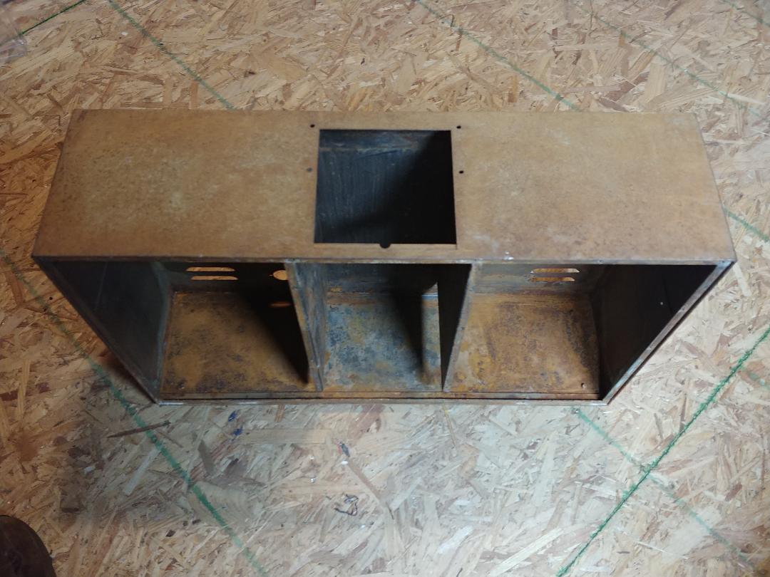
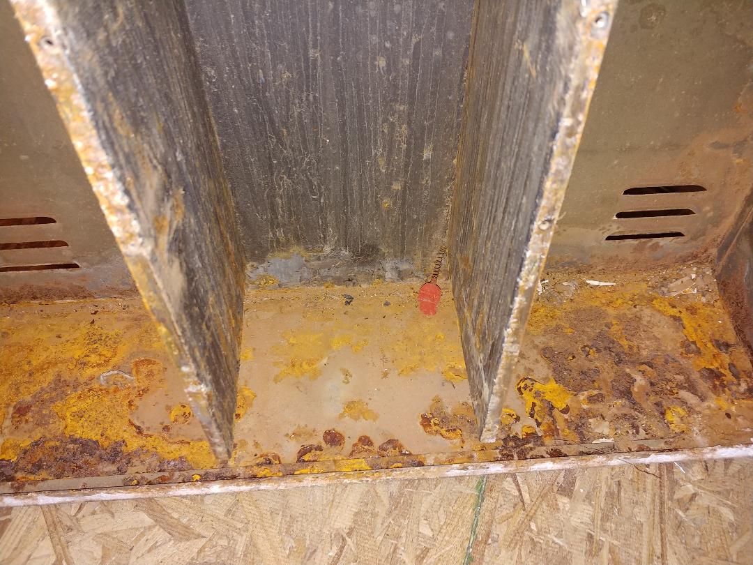
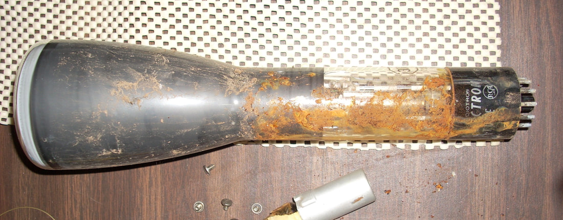
The cabinet is very rusty and dirty. From the seller's photos of the exterior I suspected it had been in a damp environment at some point. But after removing the case it's obvious it was much worse than that: it's actually had water run down into the cabinet. It looks like water might have run in around the open top and down between the CRT shield and the CRT. These are the kinds of details auction sellers conveniently forget to mention. But on the bright side it doesn't look like it's ever had mice in it.
|
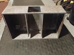
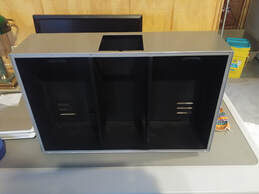
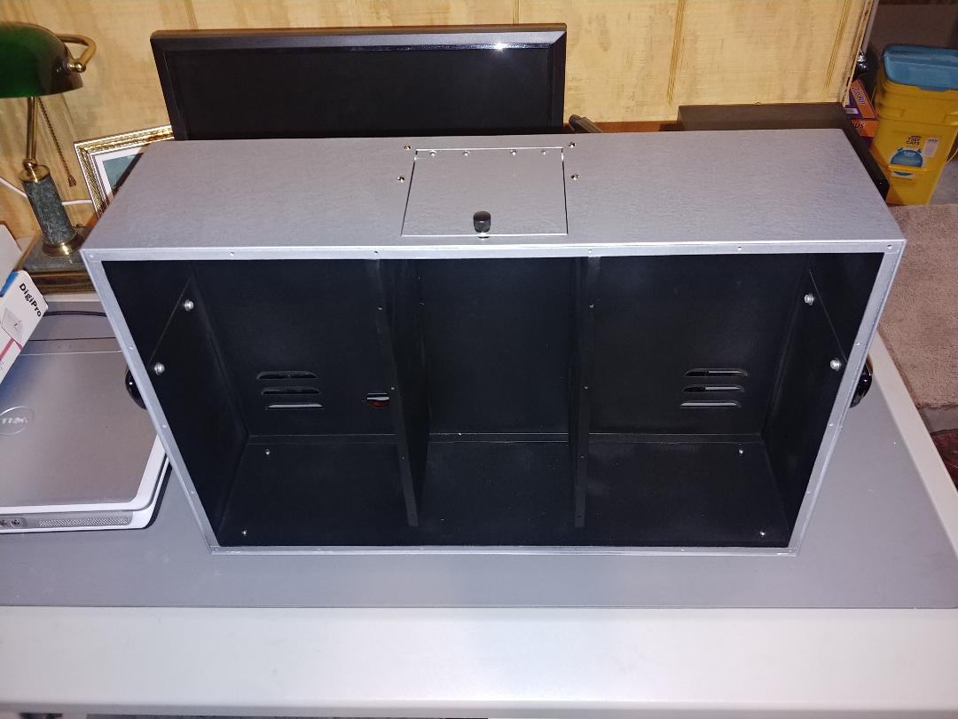
The cabinet had to be sand blasted to remove all the rust. This took repeated cleanings over several days because my air compressor is too small for the sand blaster and I didn't want to overheat it.
|
|
|
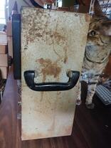
Side view with the handles reinstalled.
Not shown are the large rubber feet on the bottom. They were still soft, but dirty, and were reinstalled with new hardware after a thorough cleaning. |
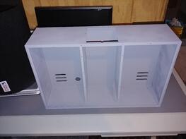
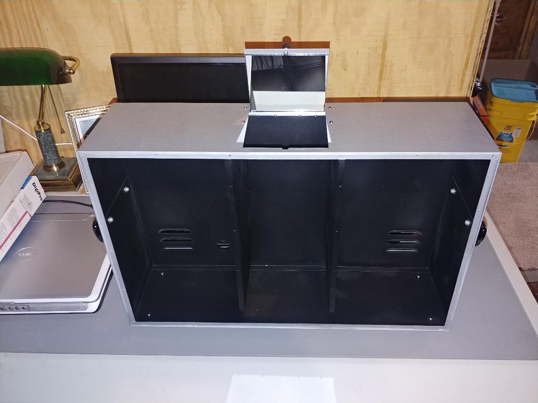
The new top door all finished up and installed.
|
The mirror can be adjusted to any angle needed for a seated person to view the o'scope. This completes the work on the cabinet. Now on to the electronics.
|
The Sub Panels
The shielded boxes of the two generators helped save the day by protecting the main generator components. But there is still a light coating of rust dust even inside the compartments. Outside the shielding it's dirt, dust and rust. And dead spiders. I hate spiders.
|
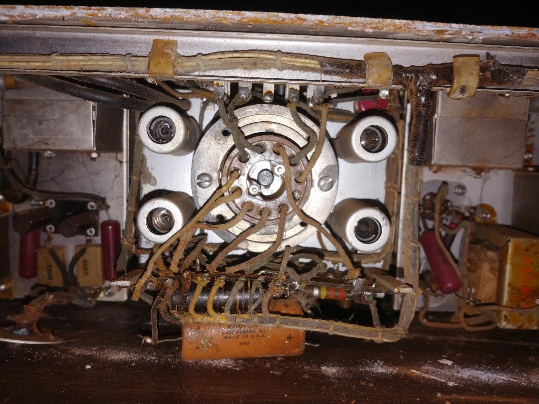
The underside of the sub panels are covered in dust and dirt, and there are dead spiders. Because the sub panels, and all the components under them, are suspended above the bottom, there's no apparent water damage to anything.
|
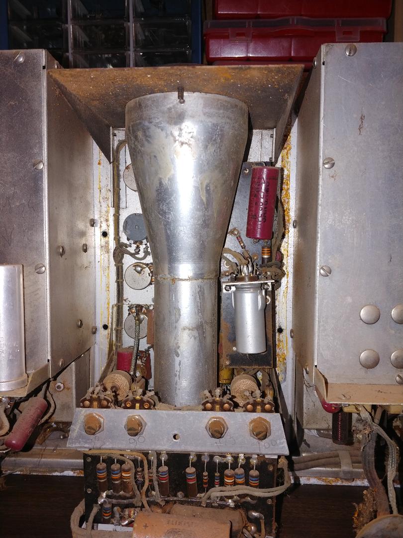
The CRT connector and the vertical and horizontal amplifiers. And more dirt, but now I'm looking for spiders.
|
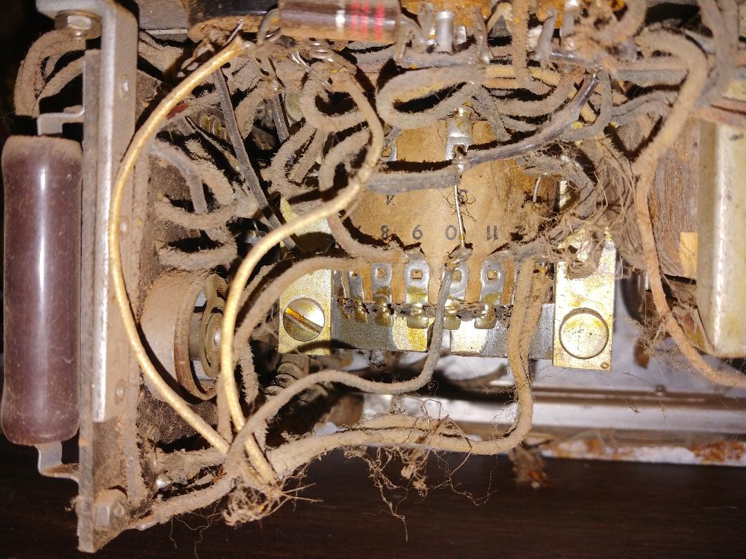
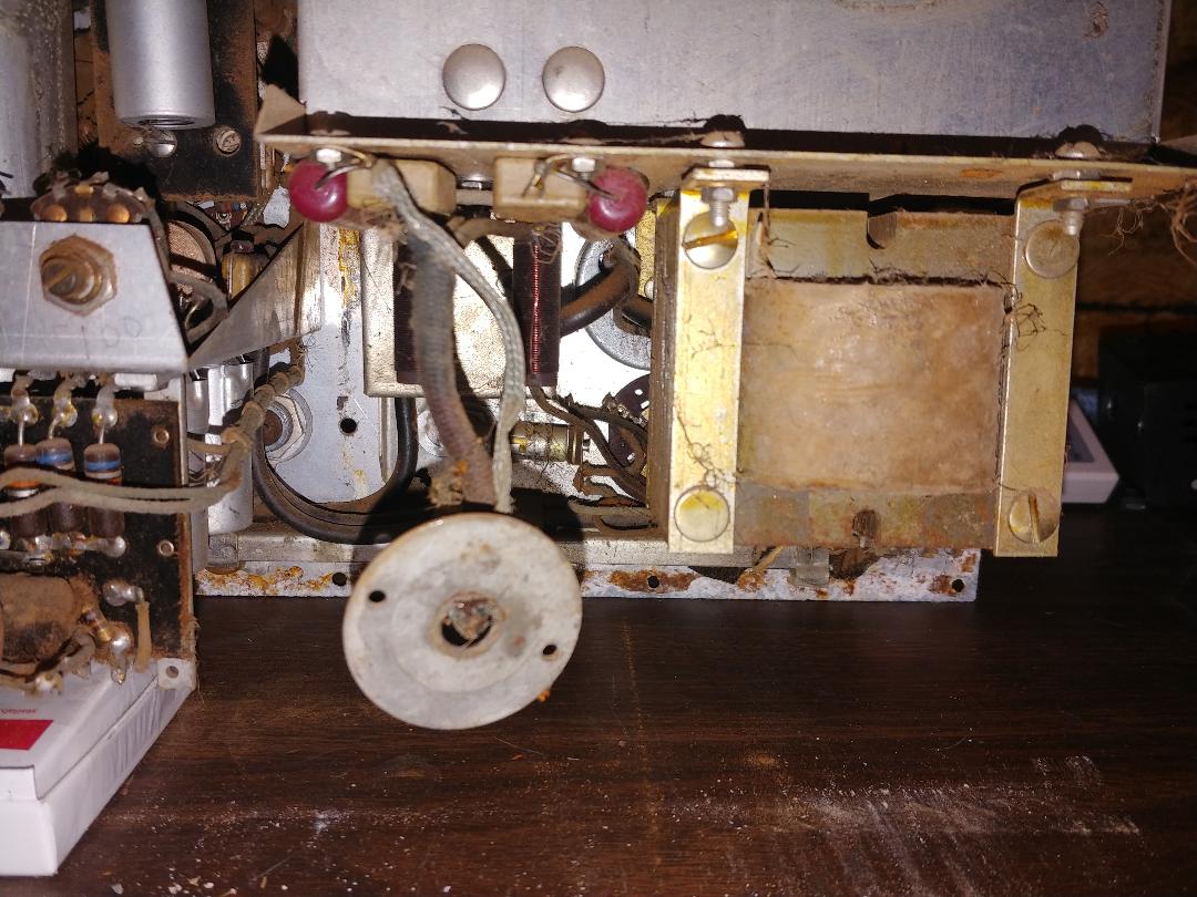
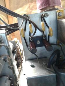
Here's the other transformer and the AC line filters. The cloth covered, shielded power cord was cut off, but the rubber-coated wires inside the braided shield were dry rotted anyway, so no great loss. I will replace it with an unshielded cloth covered cord.
|
Knobs
There are two different size knobs on the Genescope. All the oscilloscope knobs are slightly smaller than the knobs on both generator sub panels. This unit is missing four of the larger knobs. The "white" stripe on the knobs is actually a metal insert.
The steel set screws on three knobs in the o'scope section were rusted so tight I could not get them to budge, even after soaking with PB Blaster and WD-40 for a couple of days. I decided to sacrifice the knobs rather than risk accidentally damaging the front panel trying to remove them.
By cutting slots into the backs through the middle of the set screws with a Dremel tool I was able to unscrew what remained of them. Of course all three knobs cracked, but I got the darned things off without damaging the front panel and the knobs were repaired with epoxy, so I'm still only short 4 knobs.
The AM and FM Generator Dials
|
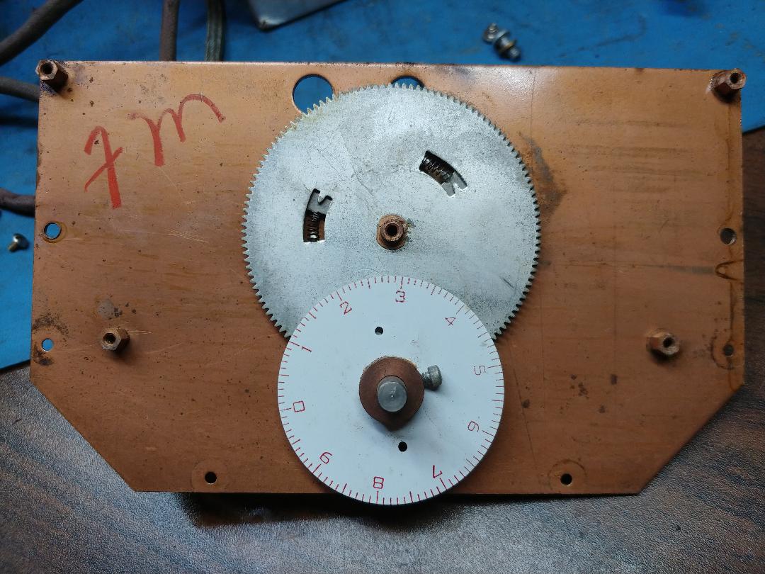
The generator dials weren't too difficult to remove, that is once I figured out which screws to unscrew. There are three screws through the sub panels into the back of the dials and a set screw on the pointer shafts. The FM generator horseshoe will fall out as its dial is removed because there is no other support in front except the dial. I did not touch the screws on the rear pivot of the horseshoe to avoid having to realign it later. I notice the gears in the dials are spring-loaded anti-backlash for better precision.
|
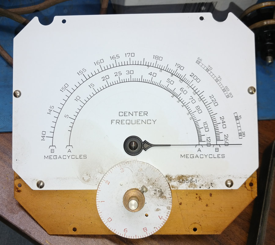
Both the AM and FM dials are functional. The AM generator dial needs cleaned and the Bakelite escutcheon is cracked, but it's a clean break and should be easy to repair. I think someone was trying to pry the face off.
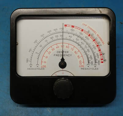
The FM dial is in better shape but also needs cleaned. The red logging scale on both dials has faded away. Not sure how I'm going to fix this yet... |
Removing the Faceplate
Once the knobs and dials are removed the only things left to remove are the control nuts, panel lamps and the output connector. I discovered that some of the controls have different thickness nuts and internal lock washers. It's wise to take notes when removing them or the knobs will not be equally spaced away from the face plate when everything is reinstalled. And it can be a real pain trying to change lock washers behind the panels on certain of the controls. Don't ask me how I know. Apparently some of the switch and control shafts are slightly different in length and the different size lock washers correct for this.
The thicker nuts are used on controls that mount directly to the sub panels where the front panel has a large hole for the nut to pass through. The extra thickness allows the nut to protrude past the front panel just enough to get a nut driver on it.
The thicker nuts are used on controls that mount directly to the sub panels where the front panel has a large hole for the nut to pass through. The extra thickness allows the nut to protrude past the front panel just enough to get a nut driver on it.
|
The face plate is off. Removing the face was necessary to clean and restore the sub panels and to clean the corrosion from the back of the face plate where it was in contact with the steel cabinet. The aluminum is pitted and encrusted in places with rust from the steel so the back was taped off and the affected areas sandblasted clean. The sandblasted areas will be painted to seal the surface.
|
The three sub panels after removing the face plate. At this point only the bar across the bottom, and the wiring, is holding them together. I'll restore one sub panel at a time, starting with the o'scope in the middle, because it's in the worst condition.
|
Restoring the Oscilloscope Sub Panel
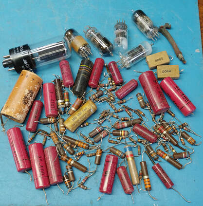
I spent hours cleaning the oscilloscope section as I restored it, using a variety of cleaners and rust remover. It took a lot of Q-tips and scrubbing with toothbrushes to remove the years of accumulated crud, but it looks worlds better now. Nearly every capacitor and resistor was replaced and all the control pots were flushed with contact cleaner and in some cases disassembled and cleaned. Even the CRT needed a scrubbing. All the switches needed cleaning and contact cleaner alone wasn't enough, I also had to use Deoxit on them (I ended up using Deoxit on every switch in the Genescope).
|
The first step was to remove the CRT. It was fairly easy to remove by following Simpson's instructions to gently pry up the tube's base and pop it out of its socket. I have a small vintage pry tool from GE just for popping out tubes and such, but a small screwdriver also works.
|
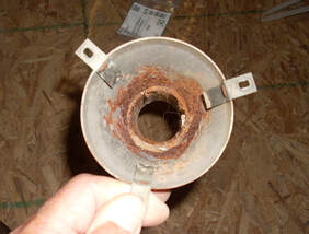
The CRT shield was crammed with dirt and rust all around the neck of the CRT. Looks like water ran down between the shield and tube.
|
The CRT shield after sandblasting off the rust and coating the interior with cold galvanizing compound.
|
|
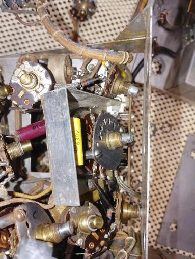
To replace the capacitors in the scope section I had to pretty well disassemble the whole sub panel. Simpson even placed one capacitor behind the shield covering the front wafer of the Function switch.
All the paper capacitors were electrically leaky (the Sangamo caps may be plastic on the outside but they are still paper and foil on the inside). The only caps not replaced are the mica capacitors on the Sweep Range switch and one each in the vertical and horizontal amplifiers. |
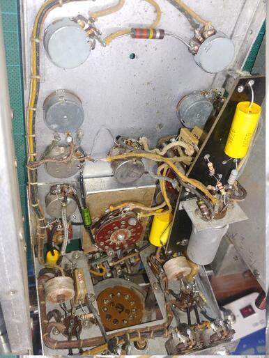
The scope section reassembled and it's a lot cleaner now. All the paper capacitors and all the resistors except the 220K resistor at the top between the two pots have been replaced.
All the resistors had drifted high and were out of tolerance or very close to it. Just the one 220K was still well within 10%. The CRT won't go back in until the Genescope is ready for testing. |
Four of five 6J6 tubes in the vertical and horizontal amplifiers, and the sweep circuit, had one side much weaker than the other. Four new RCA tubes were installed in the amplifiers and the one good original tube was reused in the sweep circuit.
Restoring the FM Generator Sub Panel
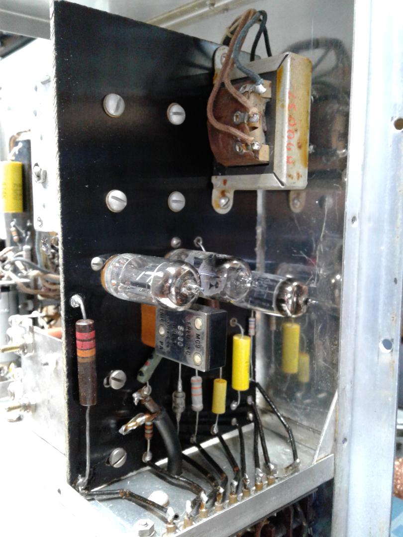
The FM shielded compartment had to be disassembled to get at all the generator components. Almost all of the resistors and all the paper capacitors were replaced. The two 6AK5 tubes and one 6C4 tube tested good, but the getter was white in the other 6C4 (V7), indicating a problem, and sure enough it was bad. It was replaced with a new tube.
|
|
|
All resistors for variable oscillator V4 were out of spec and replaced. The capacitors are ceramic and still good.
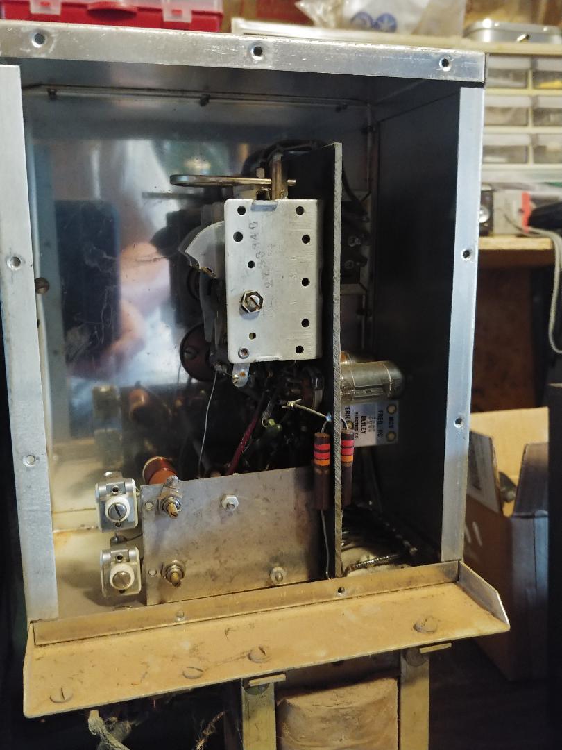
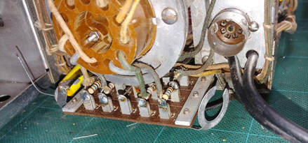
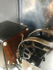
The Bakelite box houses the sweep motor. The easiest way to access the motor is to remove the housing's panel screws and then the 3 screws holding the box to the chassis. The box can then be slipped off to expose the motor. |
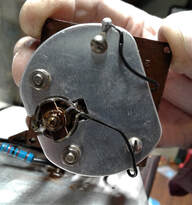
The sweep "motor" is actually a meter movement. This is delicate stuff so after a few photos the box went back on. No resistors or paper capacitors in there.
This is a part that's irreplaceable short of buying another unit to pull one from. It's good Simpson put it in its own housing for protection, and it appears to have survived the years unscathed. |
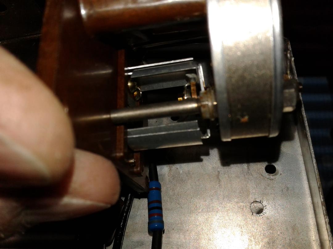
Here is a side view of the motor. Looks like the movement swings the small vanes back and forth with the AC drive signal creating a variable capacitor.
|
|
Unsoldering the coax line allows the center panel to swing out to gain access to the components mounted behind it.
|
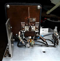
All the "roundy" resistors and paper caps behind the panel were replaced even if they were still in tolerance because of the difficulty in getting to them. Resistor R20, a 6.8K 2-watt resistor, was open. The only resistor not replaced was R19, the 7.5K wirewound resistor.
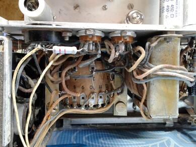
The Band "A" position on the switch was not working and needed cleaned with Deoxit and contact cleaner. |
Sometimes even the factory makes a mistake. On the lower center black wire the solder does not wick onto the wire. This wire goes to the rear motor terminal.
With a gentle tug the wire came right out of the solder ball. This bad solder joint appears to be straight from the factory and has gone unnoticed for over 60 years. |
Restoring the AM Generator Sub Panel
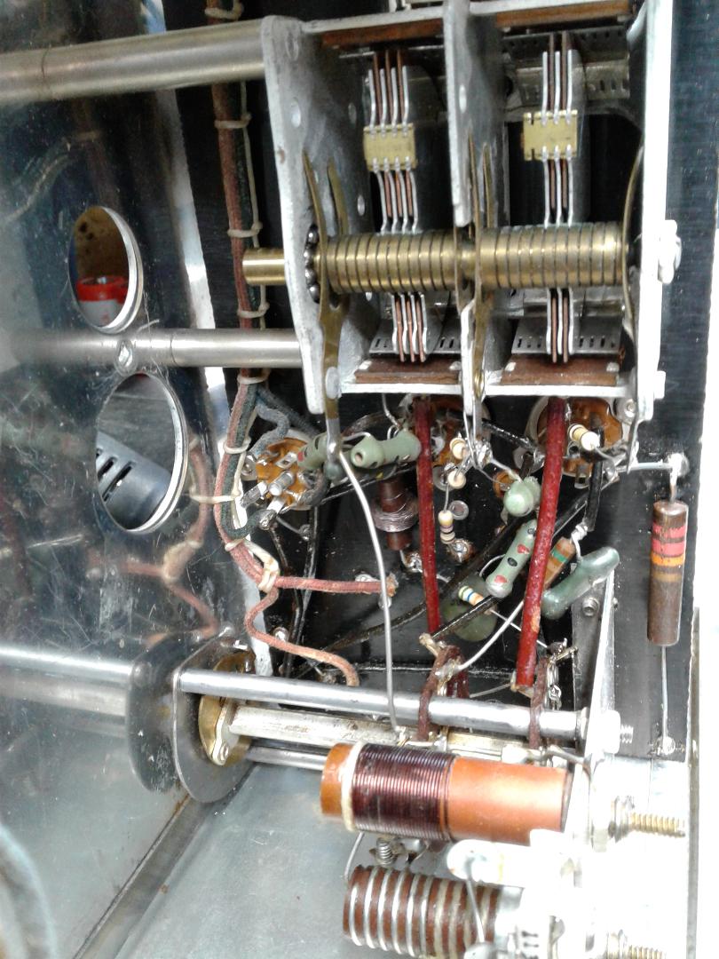
The AM generator is a little more open than the FM side, but still a pain to get at some components. All the out of tolerance resistors and all paper caps were changed. A couple of resistors were newer Allen Bradley style and still in spec, so they were left. The rest of the resistors were the older "roundy" style and all but three were out of spec. Those three are the 22K 2-watt 5% resistors. If they ever need changed they are easy to get to.
|
The tube side of the AM generator board. All three tubes checked good.
|
Another angle of the top of the board. The shielding around the generator sub panels unscrews to allow better access to the components.
|
The back side of the AM board. It's a bit tight to work on but not quite as bad as the FM side.
|
Restoring Components Mounted Under the Sub Panels
There's a lot of components mounted under the three sub panels. Some, like the attenuators, are associated with the AM and FM generators and most of the rest is the power supply section.
AM and FM Attenuators
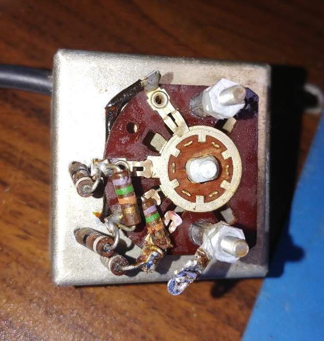
Inside and back of the shielded FM Attenuator before and after repairs. All the resistors had drifted high, some more than double their original value. To replace them the switch had to be completely disassembled, which is harder than it looks because there are wafers on both sides of the inner shielded box. I took photos before taking it apart to be sure I could get it back together correctly. The AM Attenuator is nearly identical to the FM section.
|
Inside of the AM Attenuator. The only difference from the FM side is one less 91-ohm resistor. Both generators are 75-ohm output impedance and the coax is RG-59U.
|
On the AM side one of the dual potentiometers of the Signal control has a 75-ohm resistor across it that has drifted high. It's under a shield which makes it a little harder to get at, so I replaced the resistor and cleaned the control while the AM Attenuators were removed which made it easier to access.
|
Power Supply Section
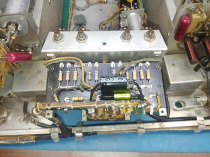
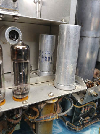
Just like the other sections all the resistors and capacitors were replaced. I restuffed the electrolytic cans C54 and C56 with new caps to keep the power supply looking original.
|
I originally replaced the electrolytic capacitors by mounting new caps on a ceramic turret block. That worked OK, but I thought it made the power supply look a little cluttered. So I pulled the block and rebuilt the power supply again by stuffing the old electrolytic cans with new caps. Looks much cleaner now.
|
At this point all the known bad components have been replaced. Power on testing will reveal if anything more needs to go. Next the two generator dials need cleaned and the dial's scales restored. Then everything can go back together and the Genescope will be powered up on an isolation transformer and current limited Variac for testing and alignment.
Impedance Matching Output Cable
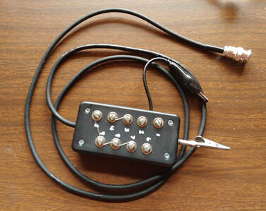
Haven't had much time to work on the dials and my computer with my graphics software crashed, so I decided to work on something a little more fun and recreate the signal generator output cable and termination box. Nothing fancy, just made from parts on hand.
|
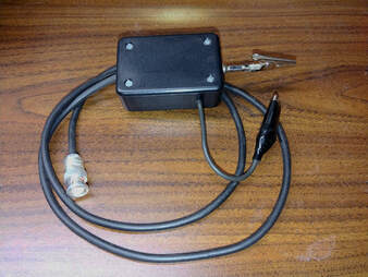
The completed termination cable. I have it strapped for 300-ohms in the photo. The case is an old Radio Shack project box and digging through some parts drawers turned up the appropriate alligator clips. The coax is 75-ohms to match the generators.
|
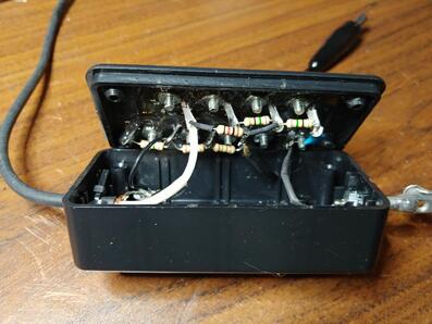
Inside it is wired according to the schematic in the 480 manual. I made the nine screw terminals by first soldering lugs to some 6-32 nuts. Next I drilled and tapped the top of the box, threaded 6-32 screws through the top and screwed the nuts on underneath. Then the nuts were epoxied in place.
|
High Frequency Probe
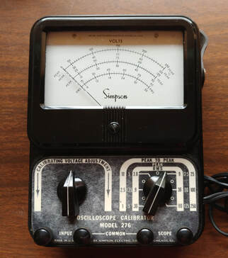
The Simpson Model 276 CalibratorAnother accessory Simpson sold for use with the Genescope is the model 276 Calibrator. It's AC operated and provides an adjustable sine wave output to the scope that is set and read on the meter. In use, the scope's vertical input is connected to the output of the model 276 and the signal to be measured is connected to the calibrator's input terminals. Every other switch position of the voltage selector passes the input signal directly to the scope so the signal amplitude can be adjusted and noted. Then the selector switch on the 276 is changed to the appropriate voltage range and the Calibrating Voltage Level control is adjusted so the calibration voltage displayed on the scope is the same amplitude as was the signal. The voltage is then read on the meter. There's a diagram and complete description of the process in the 1958 Howard W Sams book "Know Your Oscilloscope".
|
Spare Parts Have Arrived
|
I found a Simpson 479 AM/FM Generator at a very reasonable price and bought it for spare parts. It has the same generators as the Genescope and most of the power supply section, but doesn't have the oscilloscope. The dials are still readable including the logging scales so I will use these dial plates on the Genescope. I will also pull the four missing knobs and the AM Generator dial Bakelite escutcheon for the 480.
I plan to put the old dial scales and the cracked escutcheon back on the 479 and when time permits restore it too. It's too nice to junk. |
Restoring the Dials
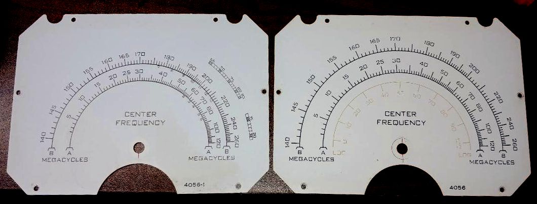
The dials need a cleaning and the Bakelite polished. The big issue is the faded red ink of the logging scales. I can replace the AM dial with the one from the model 479 generator that isn't as faded, they are identical, but I discovered there are two versions of the FM dial.
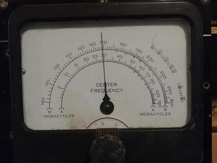
I also discovered on closer inspection of the original dial that there is a faded UHF scale I missed seeing before, and a label -"UHF CHANNEL NUMBERS".
I also discovered on closer inspection of the original dial that there is a faded UHF scale I missed seeing before, and a label -"UHF CHANNEL NUMBERS".
|
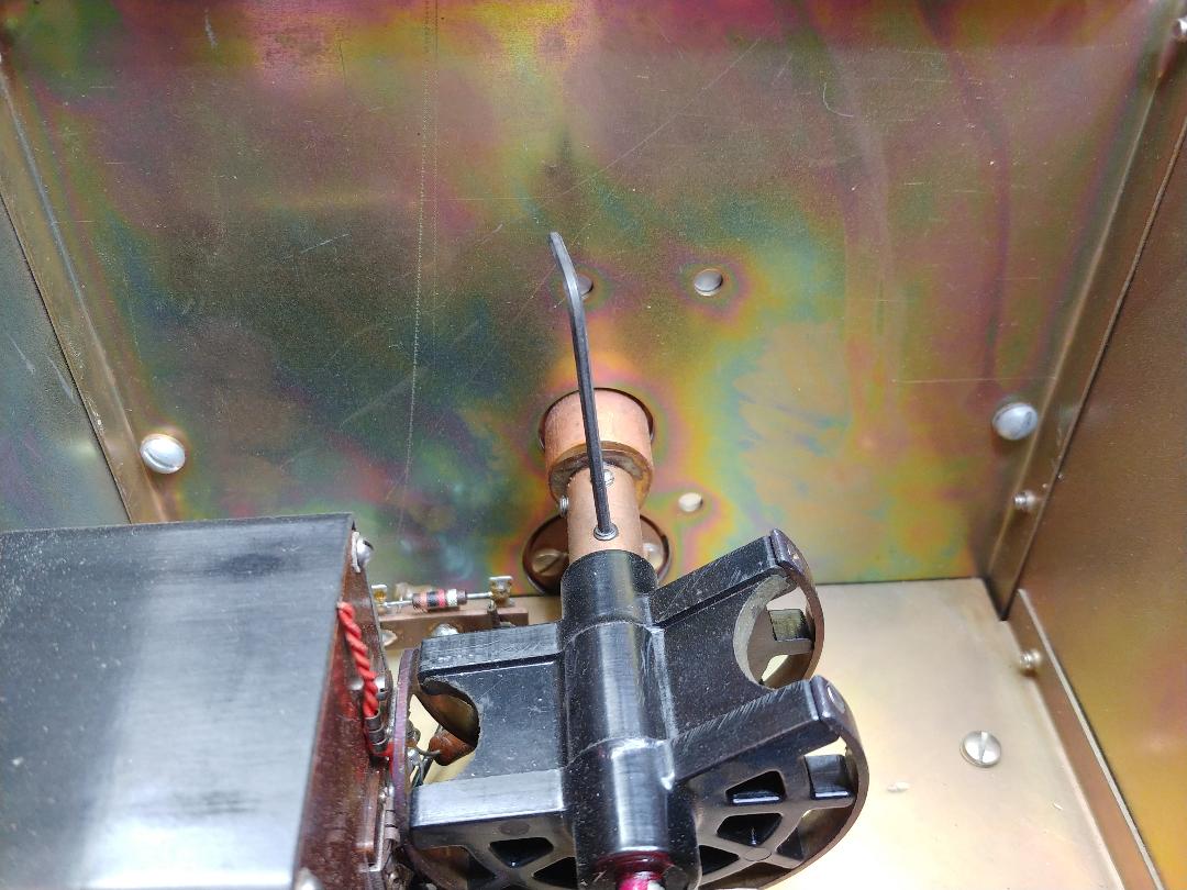
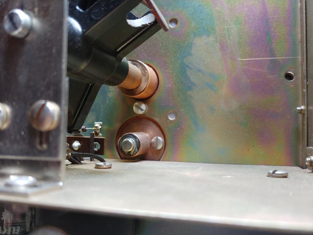
To remove the dial assembly there are three screws inside the sub panel. Two are seen in this photo, plus the set screw (with hex key inserted) to release the shaft of the horseshoe (FM) or variable capacitor (AM).
|
The third screw is directly below the drive shaft of the dial assembly. This center screw is shorter than the two outer screws because of less clearance inside the dial.
|
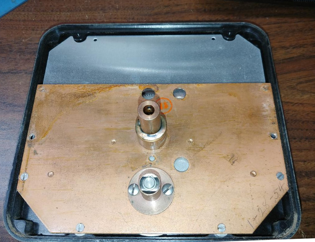
The back of the dial assembly. The penciled in date is in the lower right "corner".
|
|
The model 479 has a handwritten date of 1952 inside its dial, and does not have the UHF channel numbers and scale. The Genescope FM dial has a date of 1954 and has both the numbers and scale. And because the 479 generator dial has no UHF scales, the other three scales are larger. So it looks like I'll still have to restore the logging scale on the original dial and use it after all. |
The dial gears after removing the dial scale plate. Fortunately, the red numbering of the vernier is still readable on both dials.
|
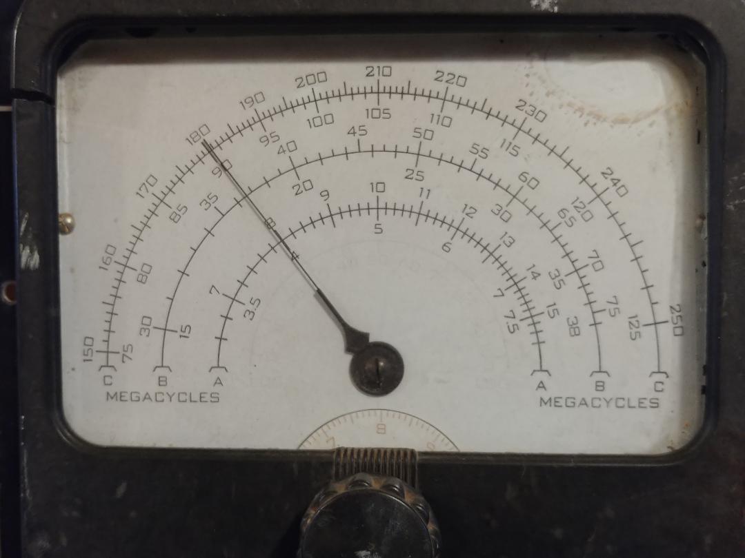
Finally got the dial face for the FM generator done. Here's a before and after comparison. All the missing red ink is back. It's not perfect, but it is functional. Now I need to get the FM side put back together. The AM generator is already reassembled, and the face plate and knobs are already back on the unit.
Finishing Touches and Calibration
Front and rear of the finished Genescope. I left some of the generator panels off for testing. I've reinstalled the CRT and the next step is powering it up. On the front panel the old, obsolete Amphenol jack's have been replaced with SO-239 bulkheads. I wanted BNC jacks but I used the 239's instead because they were the best fit for the large holes in the panel. I'll just have to use BNC adapters on them. The front panel has such a mirror finish you can see the reflection of my hands holding the camera.
When the face plate was off the unit I was able to remove all the shielding panels around the two generators to make it easier to work on the sub panels. When reassembling everything the inside shield panels, on either side of the o'scope, need to go back on before reinstalling the face plate, or two of the three inside shield screw holes down the front edge become virtually inaccessible. The catch 22 is, if you need to work on the o'scope afterward you'll have a more difficult time of it. Since I hadn't yet powered up the scope I left the panels off. After I finished with the scope testing I was able to get the top and bottom side screws back in, but no amount of futzing around with forceps and needle nose pliers got the center screws back in.
I did have a couple of issues with the scope. First I had to replace the 6J6 in the horizontal sweep generator. It tested OK originally but I see it's getter spot has turned white and it tests bad now. I also had forgotten to reattach the ground wire of the Sweep Range switch causing all but one sweep range not to work. I could also push on the sweep generator board causing the sweep to stop. I had replaced all the components in the sweep circuit, but not the original wiring, and all the frayed cotton ends of the wires made it difficult to see what was going on. So I removed the CRT again, pulled the board back and replaced most of the old wiring with new cloth covered wire. That took care of the problem, and it looks better too.
While I was doing a final inspection, looking for solder balls and cut off leads that might have fallen into the circuitry, I discovered two 56K resistors hiding under the two chokes in the scope vertical and horizontal amplifiers. One was in spec but I had to dig the other out and replace it. And finally, I had to change the 2.7K resistor R78 to 3-watts because the 2-watt metal film resistor I originally installed was getting discolored by the heat. I calculated it is dissipating 1.7 watts.
|
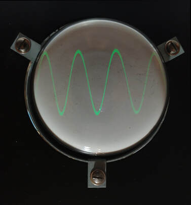
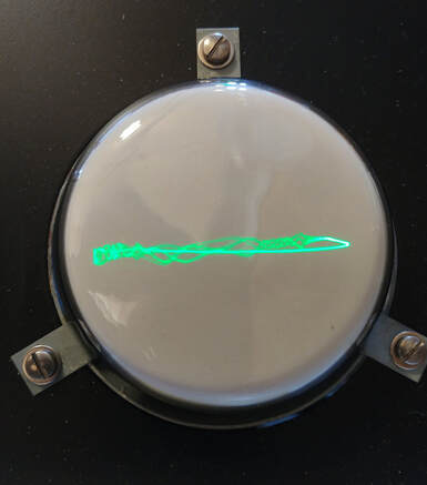
It lives! The oscilloscope is functional now and both generators are putting out signals. There's still a lot of testing to do: first confirming all the power supply voltages are correct, next testing all the functionality of the AM generator and calibrating it, and then doing the same for the FM generator. The AM gen is used to calibrate the FM gen so it needs tested first.
The scope is needed for alignment too, so I followed the steps on page 49 of the manual to realign it. |
I have a schematic for the unit, but it has no voltages listed on it, except for three handwritten ones someone added, but I know are not correct. The 5Y3 rectifier output is penciled in as +350V. However the filter capacitors are rated at 350WVDC so the B+ has to be less than that. I originally installed a 5Y3WGTA (a military grade tube) in place of the weak original 5Y3, and it gave me a B+ of 230V at the choke input. So I pulled it and installed a standard 5Y3GT which raised the B+ to 250V at the input side of the choke and 230V out of the choke. It also brought the outputs of both 6X4 rectifiers up too, because all three rectifiers use the same high voltage transformer winding, so I'll stick with the standard tube.
The outputs of the two 6X4 rectifiers are marked + and - 450V respectively, but again the max working voltage of the filter capacitors is 450WVDC, so the output voltage has to be lower than that. The two 6X4 outputs combined are the CRT high voltage, which is stated as 800V in another note scribbled on the schematic. With the standard 5Y3GT the outputs of the two 6X4 rectifiers is -423V and +380V respectively. That's a difference of 803V.
Also, because the -423V is getting close to the working voltage rating of C55, the 10uf electrolytic filter capacitor, I substituted a 500V rated cap just to be safe.
Interestingly, all the voltages are even higher when the Signal switch is in the Audio position. Then the B+ rises to 280V and the two 6X4 tubes are at -429V and +390V, giving a CRT potential of 819V. There is a 7000-ohm 20-watt power resistor, connected through some of the front panel switching, directly across the 5Y3 B+ line. I assume this is used to help keep a constant load on the B+ as functions are switched on or off. In the Audio position I'm guessing it is switched out of circuit.
Some notes on the alignment (and corrections to the manual)
Page 49 in the manual has the alignment procedure for the oscilloscope vertical and horizontal amplifiers.
Step 18 on page 46 is specifically for checking if the dial and horseshoe in the FM generator are aligned if the dial has been previously removed.
Page 49 in the manual has the alignment procedure for the oscilloscope vertical and horizontal amplifiers.
Step 18 on page 46 is specifically for checking if the dial and horseshoe in the FM generator are aligned if the dial has been previously removed.
|
C27 in the FM alignment procedure is the twisted wires "gimmick" capacitor on the front panel of the sweep motor housing. Untwisting it lowers the frequency reading on the dial. It is not the rear mounting bracket/pivot for the horseshoe as shown in the picture on page 45. I had to untwist it a couple of turns when checking the dial alignment at 160MHz, the zero beat was reading about 3MHz high on the scale, and untwisting it put the frequency right on the 160 mark.
|
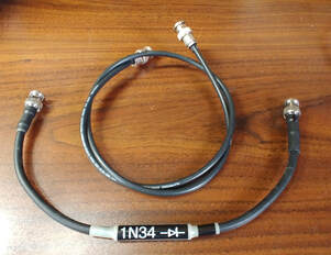
The sweep adjustment procedure on page 48 should be done to confirm the sweep is limited to no more than 15MHz, or the sweep motor could be permanently damaged. To get the oval/circle display the 1N34 diode needs to be replaced with a coax cable after setting up the generators. Otherwise you only get half a circle.
Adjusting C34. I don't have a TV IF strip to align the 140MHz fixed oscillator in the FM generator so I cheated and set the frequency using my digital storage oscilloscope's frequency readout. I pulled back the oscillator tube's shield and laid the probe on the tube to get the frequency reading. I then reinstalled the shield and checked the adjustment using the procedure in the manual.
Adjusting C34. I don't have a TV IF strip to align the 140MHz fixed oscillator in the FM generator so I cheated and set the frequency using my digital storage oscilloscope's frequency readout. I pulled back the oscillator tube's shield and laid the probe on the tube to get the frequency reading. I then reinstalled the shield and checked the adjustment using the procedure in the manual.
|
To get the claimed accuracy of the Genescope, the AM generator is zero beat against the 5MHz crystal oscillator. The FM generator dial can then be set with the same accuracy by zero beating it against the AM generator. Once a frequency is accurately set the logging scale reading is recorded. Then anytime that particular frequency is needed it's dialed in using the logging scale.
To zero beat the AM generator the Signal switch is set to the Cal position and the scope Function switch is set to 60Hz sweep. The zero beat signal is internally routed to the scope. To zero beat the two generators together a 1N34 diode is connected between the generator Output and scope Vertical input jacks. |
|
Because the 1N34 diode will be used anytime it's necessary to zero beat the FM oscillator against the AM oscillator I made it into a test fixture so it's always ready when needed. It's made from two cut off pieces of coax with BNCs attached, a piece of copper tubing just the right size to slip over the coax with the braid folded back, to make a shell covering the diode, and of course a 1N34 diode. The diode is soldered between coax center conductors and the heatshrink seals it all up.
|
It's finally back in its cabinet. This has been on one bench or the other, being worked on when time allowed, since last September and it's April now. All the functions are now working and calibrated, and it's ready to be put to work.
In operation the Genescope generators cover a frequency range from about 3 to 260MHz but the oscilloscope frequency response starts rolling off at about 1.3MHz. It works well at audio and radio IF frequencies, and to zero beat generator frequencies, but it needs the high frequency probe connected to the Vertical input to look at any higher frequency TV waveforms. I wish I had an old 1950's TV to try this out on, but I traded off my antique TVs when I moved.
I'm calling this one done.
I'm calling this one done.
Page created 9/7/2019
Last updated 4/15/2020
Last updated 4/15/2020

