
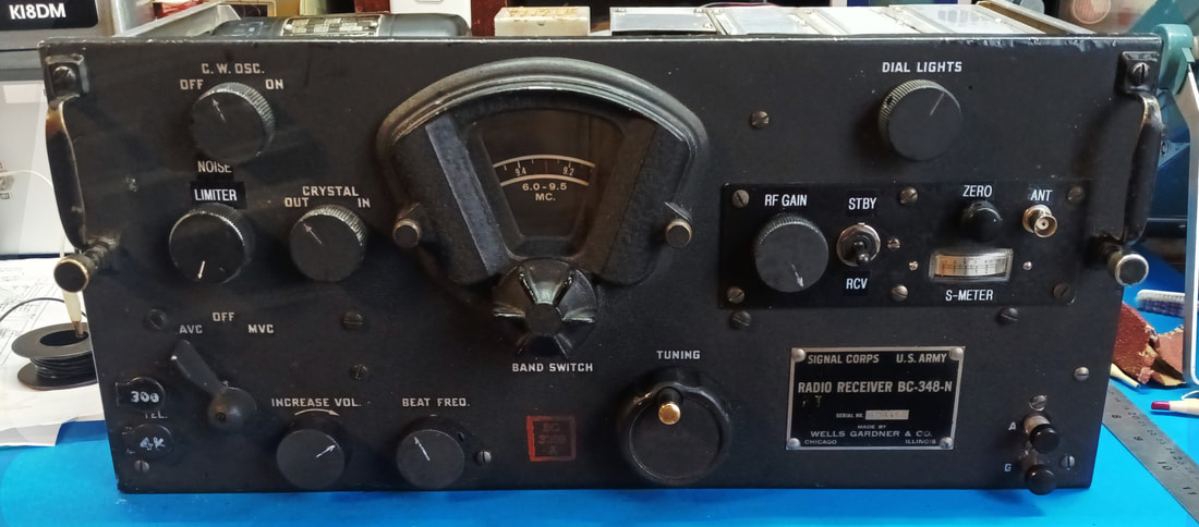
BC-348N WWII Aircraft Shortwave Liaison Receiver
|
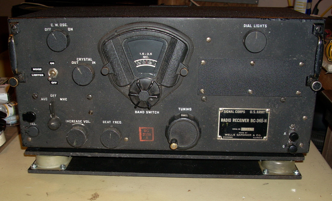
I picked up this WWII and Korean War era radio at a flea market around 10 years ago. It's a medium and shortwave receiver tuning 200 to 500Kc and 1.5 to 18Mc. It skips most of the AM radio band because its IF frequency is 915KC, which is right in the middle of the band. It doesn't have a built-in speaker and it runs on 28VDC, the battery charger voltage on American aircraft.
According to what I read online, this was the liaison receiver in American heavy bombers such as the B-17, B-24 and B-29 (the B-29 Enola Gay supposedly had one), and it was also used on large multiengine transport aircraft as well as by our Allies. |
Over 100,000 sets were produced with various updates and changes designated by letter codes and some were still in service as late as the early 1970's. This BC-348 is an "N" model and was manufactured by Wells Gardner & Co.
Un-Hacking The Radio
|
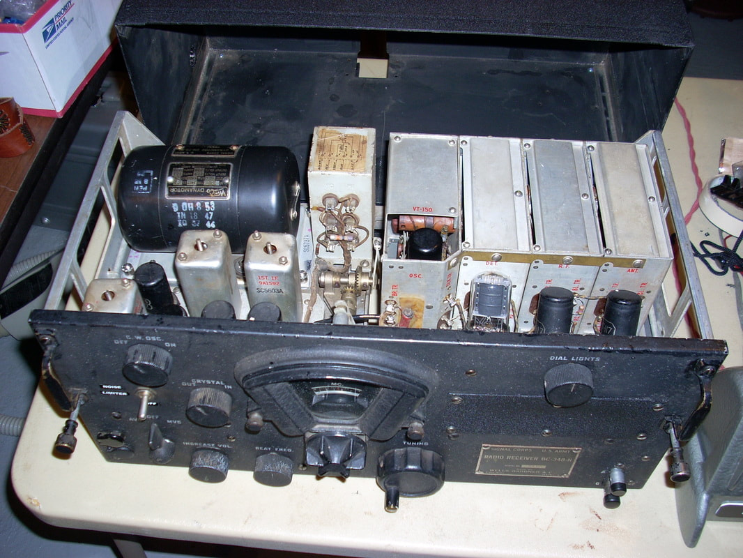
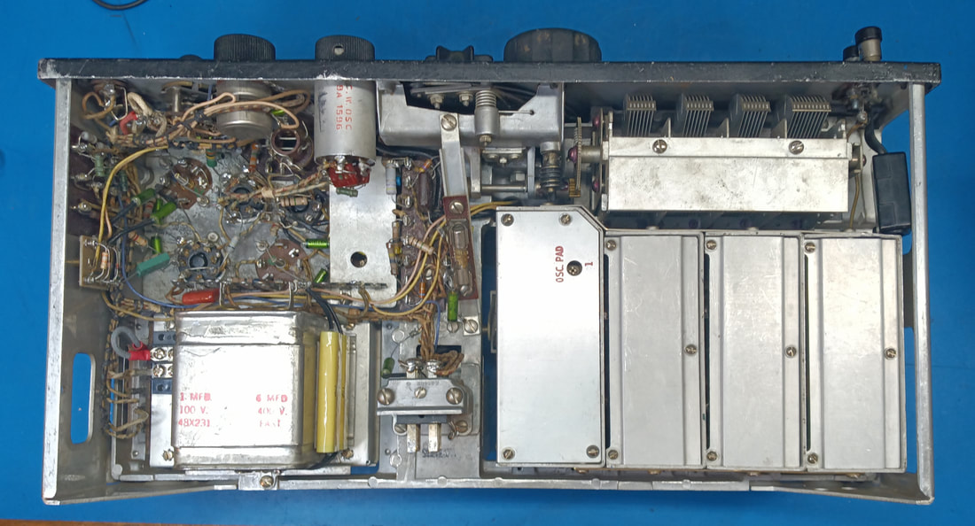
A look at the topside of the chassis. Somebody in days past did a lot of poorly wired modifications to this set, including removing:
|
These mods were taken from Surplus Radio Conversion handbooks that came out after the war. Personally, I think the handbooks should have been sub-titled "How to hack up really nice radios".
I am restoring the receiver to as close to original condition as I can, even installing a replacement dynamotor that I stumbled upon at a hamfest. The only modification I've retained from the original mods is a noise limiter circuit since there's already a hole for the switch in the front panel. I also built a 28-volt power supply to power the dynamotor and the radio's tube filaments.
I am restoring the receiver to as close to original condition as I can, even installing a replacement dynamotor that I stumbled upon at a hamfest. The only modification I've retained from the original mods is a noise limiter circuit since there's already a hole for the switch in the front panel. I also built a 28-volt power supply to power the dynamotor and the radio's tube filaments.
|
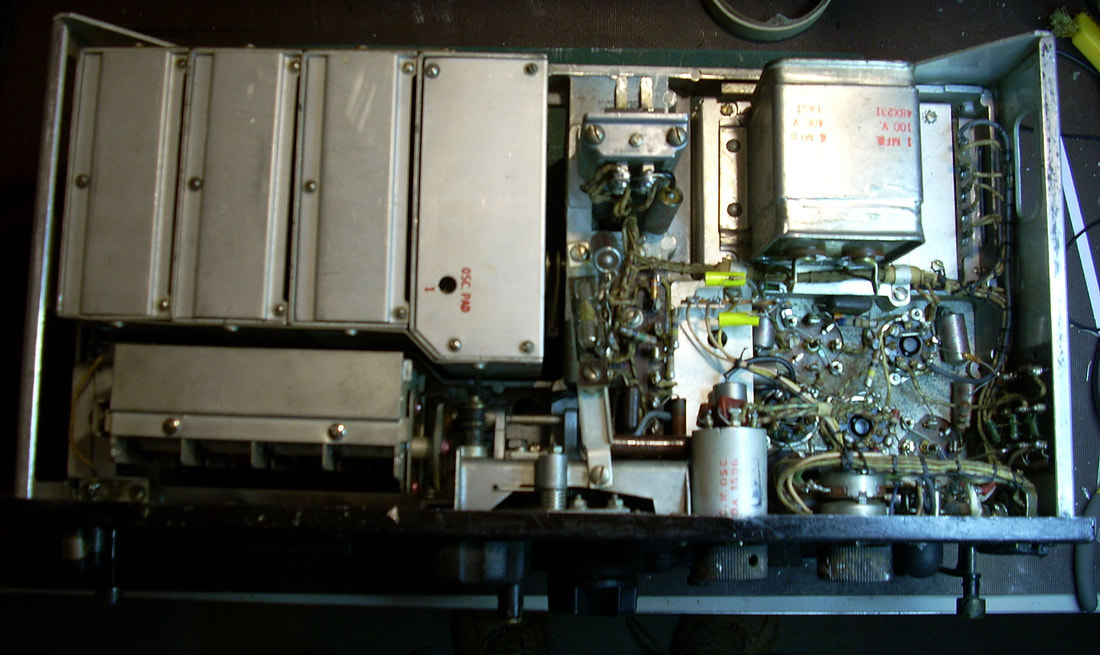
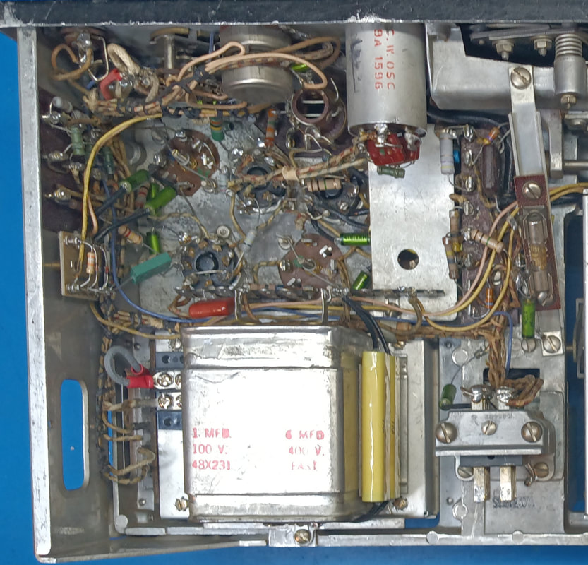
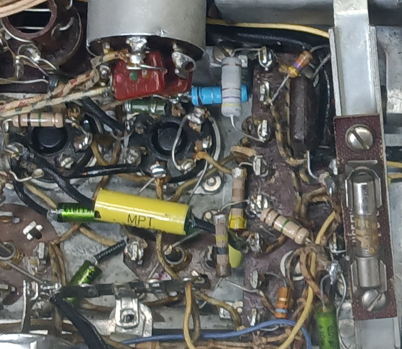
The underside of the chassis. To undo the mods I need replacement parts for the dual Audio and RF gain control, the AVC-OFF-MVC rotary switch and "toilet flusher" knob, and the dial lamp control rheostat and knob. Fair Radio Sales of Lima, Ohio came to the rescue with some original replacements from a parts set. They also had an original style of power connector (PL P-103) for the set, too.
|
Other repairs I had to make to get the set working included:
- replacing the c.w. oscillator VT-233 tube because it was weak.
- replacing several out-of-tolerance resistors, plus a couple that were just plain missing because of the mods.
- disassembling, cleaning and oiling a non-functioning C.W. Oscillator switch. It clicked when rotated but did not actually turn off the C.W. oscillator, so it was always on which may explain why VT-233 was weak.
- cleaning and lubricating the bearings of the main tuning capacitor - they were making intermittent electrical contact, causing the frequency to shift slightly when reversing directions while tuning. It was maddening to jump off-frequency every time I tried to fine-tune a station.
CW Oscillator Repair
|
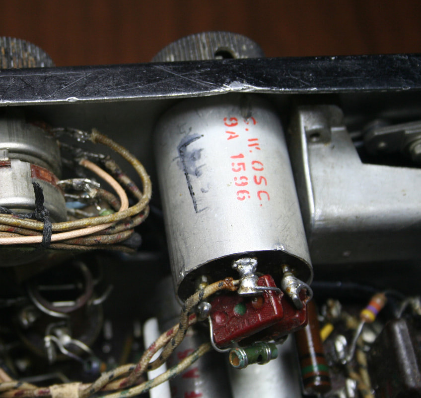
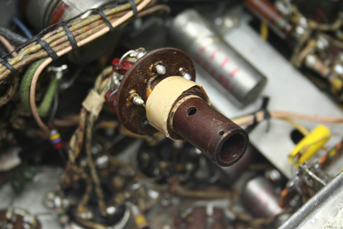
The C.W. Oscillator (BFO). Turning the front panel knob had no effect on the BFO frequency. I found the tuning shaft was sheared off inside the can by a previous owner. After the repairs below, and adjusting the frequency per the manual, it works like new.
|
|
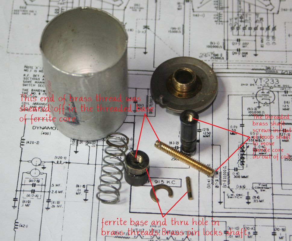
The BFO coil after removing the outer can and shaft assembly.
Not seen is a slot in the coil form on the opposite side of the form for a brass pin. The visible hole in the coil form is for inserting a tool to push the pin out the slot side when disassembling. The pin keeps the ferrite core from rotating and limits how far in and out of the coil the core can travel. |
|
The threaded screw shaft was sheared where it was screwed and pinned into the ferrite core base (the weakest point due to the hole through the screw for the pin).
The threaded knob shaft and brass screw were seized tight and would not budge, even after a good dose of penetrating oil. Apparently someone forcibly trying to turn the knob is what sheared off the brass screw. The broken screw was drilled out of both the knob shaft and ferrite base and both were rethreaded with 6-32 threads. Drilling the broken screw end out of the brass base caused the ferrite to detach from the base even though I did not drill into the ferrite core itself, just the base. After re-threading the brass base I epoxied the ferrite core back on. |
I drilled a 1/16" hole through the new brass screw shaft at the base end to accept the brass pin. The final shaft screw length (~.875") needs to allow the pin to travel forward and back the full length of the slot without the threaded shaft unscrewing from the knob shaft.
|
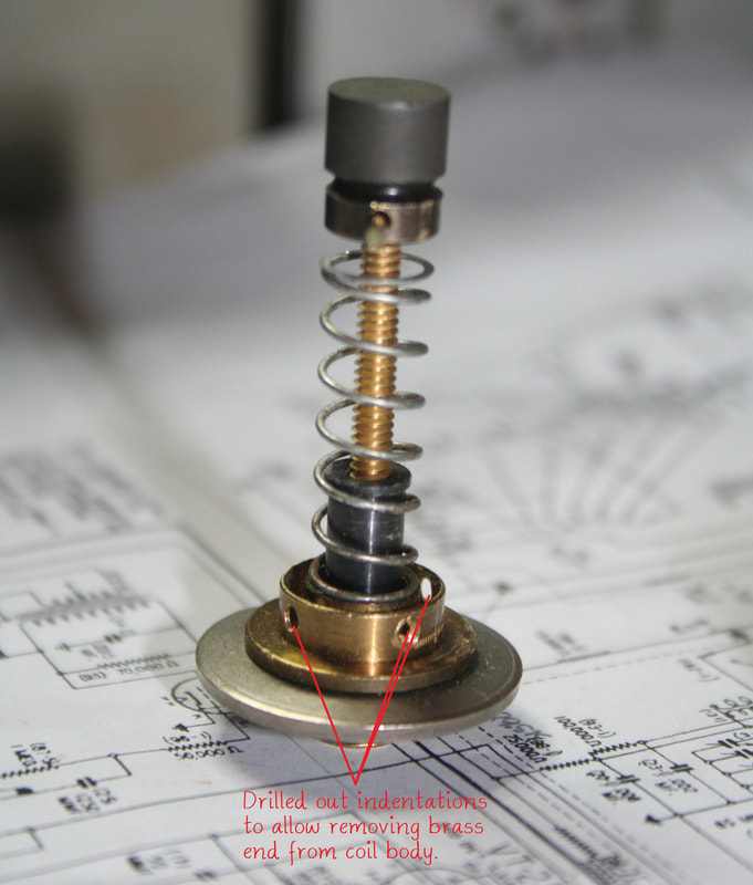
The reassembled components. After reinstalling the rebuilt assembly into the coil form, the brass pin is reinserted through the form's slot and into the hole in the core base.
When the front panel knob rotates clockwise it screws the brass screw shaft into the knob shaft, pulling the ferrite core back away from the coil. Likewise, if the knob rotates counterclockwise the threaded brass shaft is unscrewed from the knob shaft pushing the ferrite core into the coil. To disassemble the BFO coil required bending out the four small tabs on the rear of the can so it could be removed and then drilling out the four press fit indentations on the brass cap. Three of the four drilled out indentations can be seen in this picture. I only pressed the brass end back on the coil form. The snug fit of the brass cap and bending the tabs back over on the coil can seem to hold everything together just fine. |
Crystal Filter
|
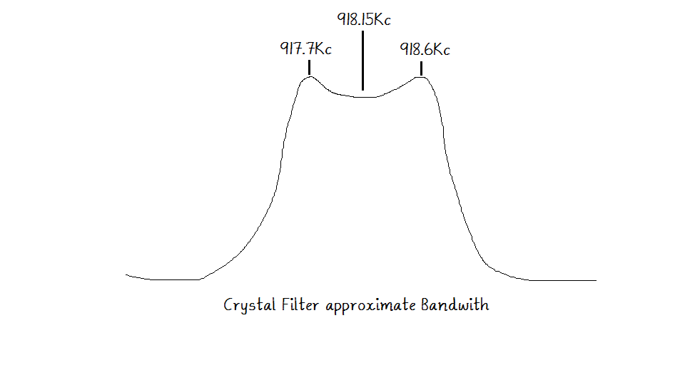
The crystal filter wasn't working so with my frequency meter and o'scope I did a rough check of the frequency response of the crystal filter in-circuit which is illustrated in the drawing. This gave me an approximation of the center frequency which has apparently drifted a bit from the design frequency of 915KC. Then I checked the IF alignment and discovered the IF transformers were peaked on ~908KC, so I realigned the IF to 918KC and the filter came to life - just needed to get everyone operating on the same frequency.
|
Noise Limiter Mod
|
A previous owner drilled a hole in the front panel and mounted a switch and a simple audio diode noise limiter. Not much I could do about the hole that didn't involve repainting the front panel, so I made a new audio noise limiter taken from an old ARRL Radio Handibook and left the switch in place. Audio diode limiters do cause some distortion in the output so I replaced it again with a modified IF limiter circuit taken from the same handbook that doesn't cause audio distortion.
|
DM-28 Dynamotor
|
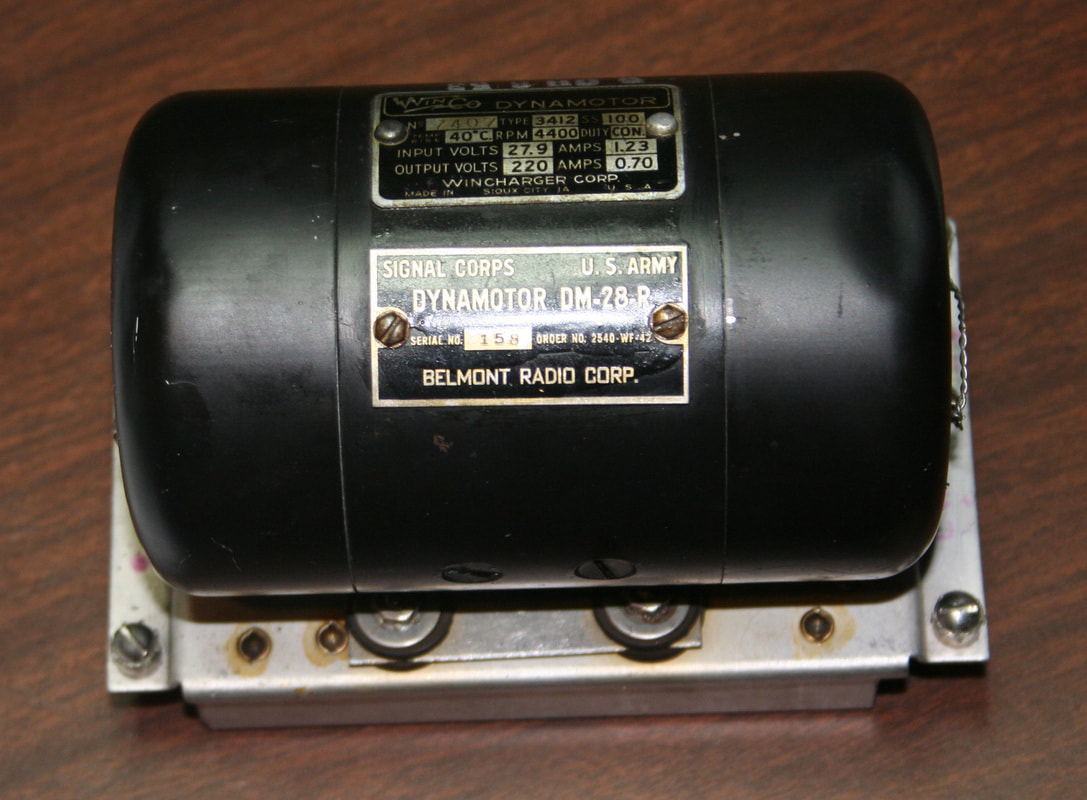
The DM-28 Dynamotor. It is a motor-generator that produces the high voltage for the tubes. Routine maintenance for the dynamotor includes re-greasing the bearings every 1000 hours or about 6 months of normal operation.
Some online comments I've seen regarding the dynamotor are that it's noisy. I'm not sure how many of the commenters have ever actually used a set with the dynamotor in it, but the dynamotor just purrs along in background, and after having run the radio on it for good while, I hardly even notice it. I think it's rather unique compared to my other radios. I actually have an AC power supply for this set, but I don't have any intentions of installing it. |
|
|
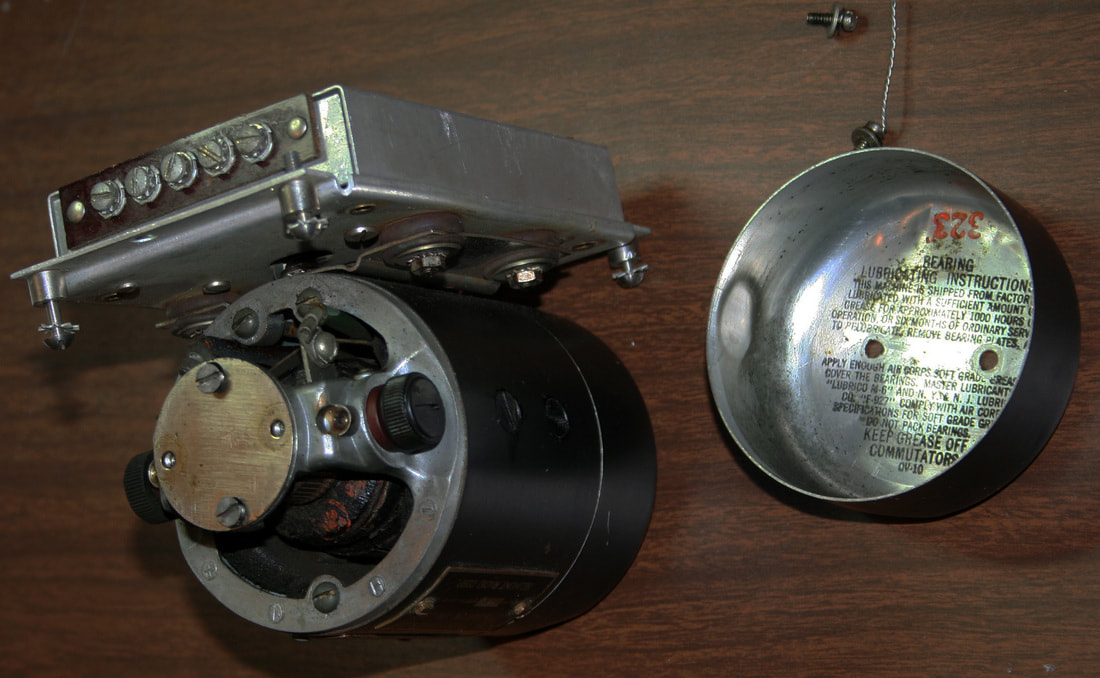
The end cover slips off after removing the two end screws. Inside the cover are the re-greasing instructions.
|
|
|
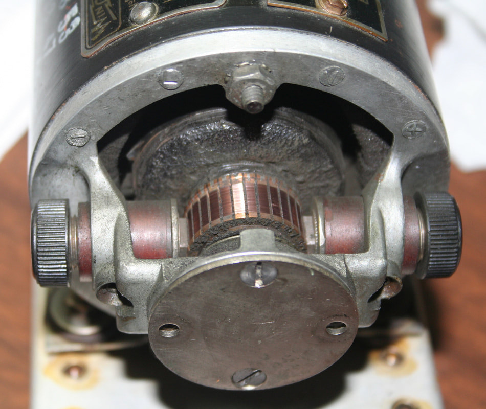
One of the two sets of commutators and brushes. The bearing is under the end plate. Both ends of the dynamotor look the same.
|
|
The cover plate, gasket and stack of spacers.
|
Adding an FT-154-J Shock Mount
|
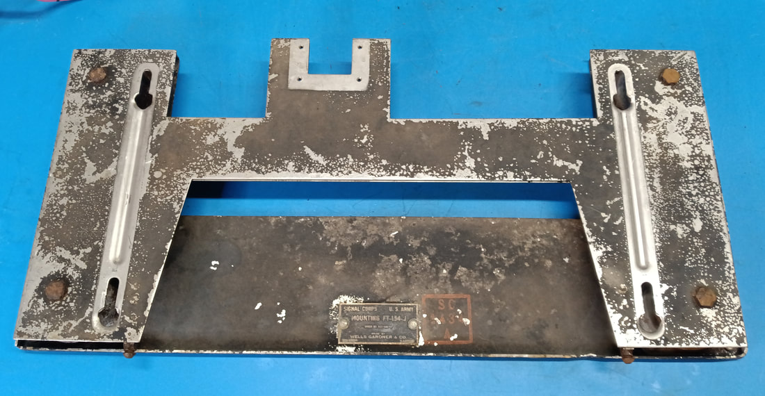
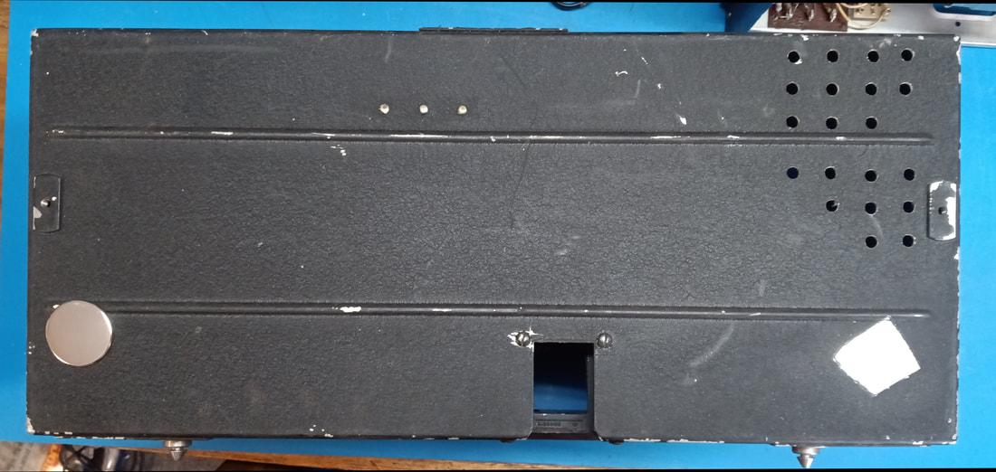
The original DM-28 dynamotors are hard to find, but an original shock mount is even harder to come by, so I originally made a simple replacement mount for the radio to sit on (see photo at top of page). It just looked incomplete without something under it, and it needed to be up off the table for the rear power connector to fit in the back. I used my home made mount for about ten years, until I recently came across an original shock mount. It's not in very good condition as found, but is complete and I will clean it up and repaint it. It was also made by Wells Gardner.
|
|
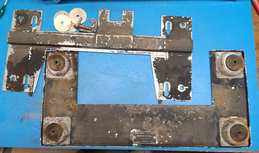
The two halves of the mount are bolted together by four 1/4" bolts and nuts, one in each of the shocks, but the ends of the bolts have been stamped down over the nuts so they won't unscrew. Nothing a little grinding couldn't fix.
|
|
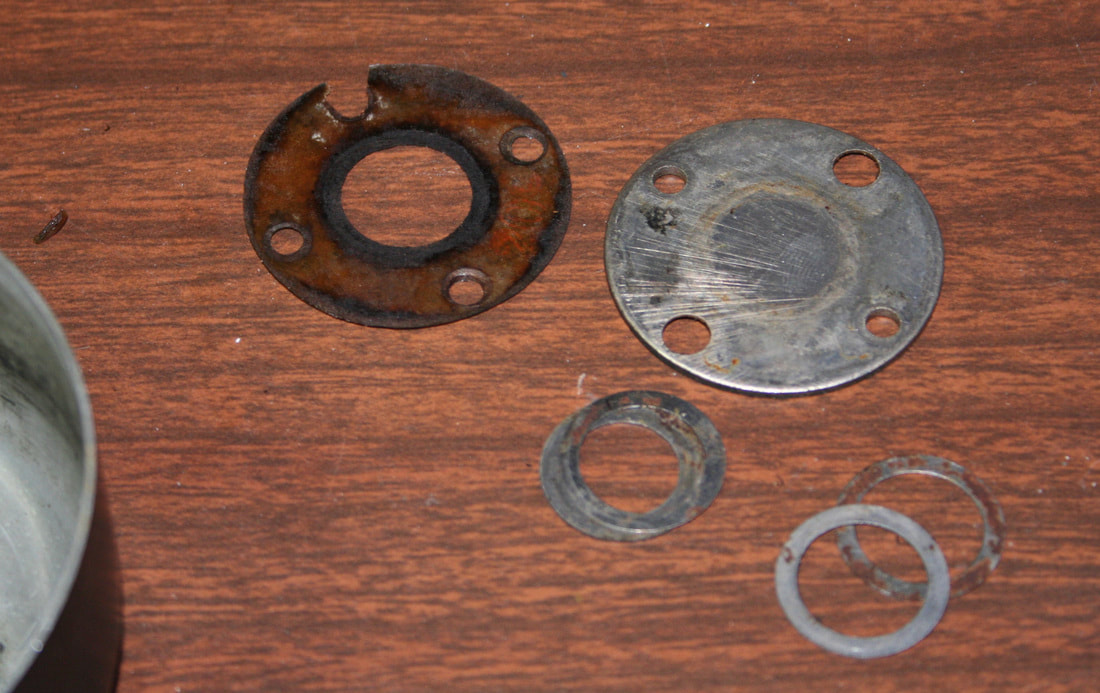
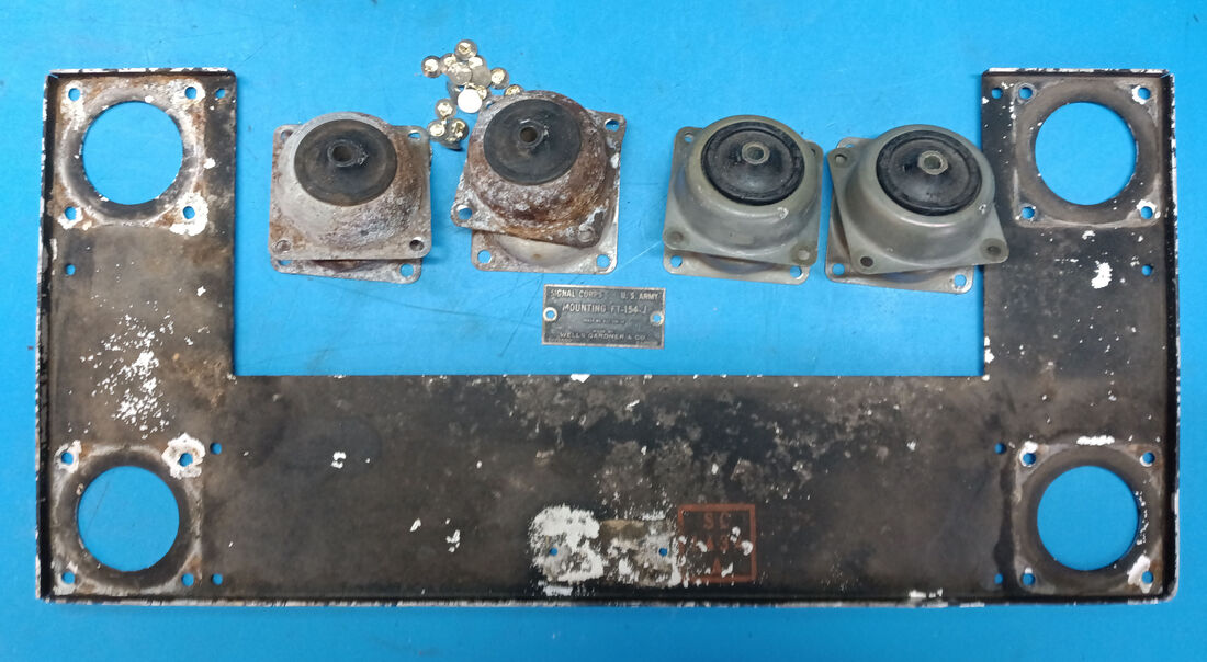
Now that the two halves are separated I removed the old, rusty shocks by drilling out the four nickel-plated brass rivets in each one. I have four new shocks ready to install that I originally bought to build my fake shock mount years ago, but now they'll be installed on the real one. They are identical to the old ones except they are labeled #12 and the old ones are #10. The new ones are stiffer so they may be rated for more weight.
|
|
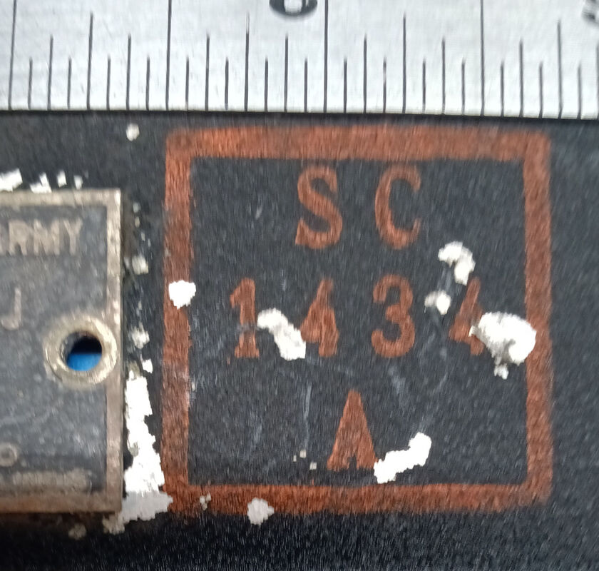
I also removed the rivets for the nomenclature tag, too, but one thing I can't remove is the orange stamp. I could try taping it off before painting or I could make a decal to put on afterwards. I'm not sure if tape would pull the old paint and label off or not.
|
|
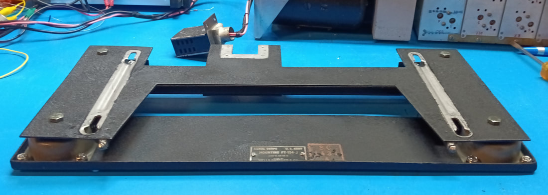
The shock mount has been cleaned up and given a quick coat of wrinkle paint. The new shocks were remounted with screws instead of rivets temporarily until I can order the rivets. Same goes for the nomenclature plate. I managed to save the original orange stamp and touched up the missing paint around it.
|
|
I thought it would just be a simple matter of pulling the old fake shock mount from my radio cabinet and installing the real one, but nothing is ever that easy. Because I had never paid any attention to how to mount the radio on a real shock mount before this, I didn't realize someone had gone to great lengths to hack up the bottom of the cabinet.
|
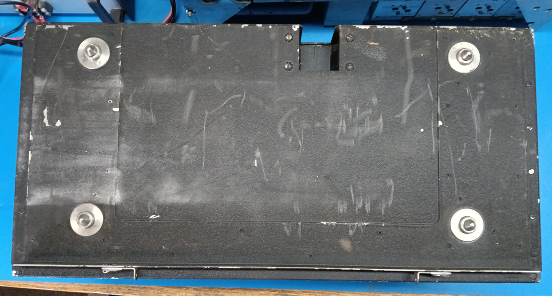
Turns out some genius decided to remove the plate on the bottom that the shock mount mates with. They meticulously drilled out ever single little rivet, and there's a bunch of them, in order to pull off the attachment plate. I see no good reason for doing this, since all they had to do was just screw some rubber feet to the bottom and call it a day. So now I had to buy another cabinet. The photo shows the new cabinet's bottom with its attached U-shaped mounting plate and pins that were missing from mine.
|
|
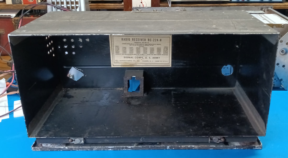
This replacement cabinet came from Fair Radio Sales. It's from a BC-224 "H" model and my original one was for a BC-348 "R", so it wasn't really the original cabinet either. But this was common for sets that were actually in service. I read that repair depots would slap a chassis in the first cabinet in the pile, because they were all interchangeable.
As can be seen, the new cabinet had a couple of holes in the back, but I've closed them up. The original cabinet had some added holes, too.
As can be seen, the new cabinet had a couple of holes in the back, but I've closed them up. The original cabinet had some added holes, too.
In the first photo the new cabinet is test mounted on the new shock mount, which is a "J" model, but like the cabinets, the shock mounts were interchangeable, too (except for the very first model which had no letter designation).
Completing the Restoration
|
The original work of restoring this set was done back before 2015. The radio's capacitors were not replaced at that time, but it's 2023 now and they really need checked and the bad ones replaced before they damage tubes or other parts. Also, the old carbon resistors are prone to drifting with age and need rechecked, too.
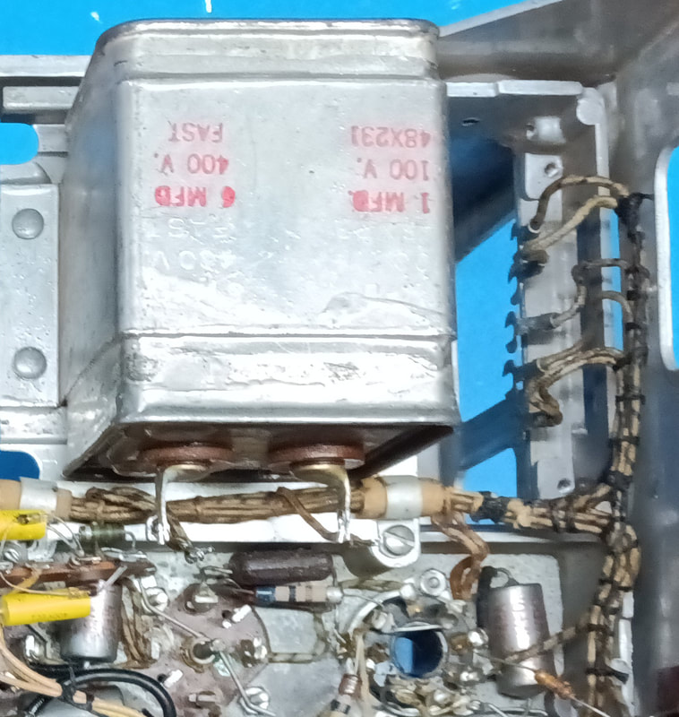
All the tubular capacitors are paper-in-oil, close to 80 years old, and testing shows they are now electrically leaky. Some are also physically leaking oil, so all of them will be replaced. There is also a large sealed can with two more oil capacitors inside which amazingly still passes a leakage test, at least up to 1GΩ anyway, but the caps in it will still be replaced as a precaution. The can itself is not physically leaking oil so it can be left in place for originality's sake. The wires to it will be pulled and soldered to terminal strips that were added for attaching the replacements. In all, 18 oil capacitors were replaced. |
The mica capacitors were also tested but none of those were bad. I've seen claims online about BC-348's having Micamold paper capacitors, but I did not find any in this set. Maybe the online comments were referring to the older grid cap circuit in earlier sets. All these mica caps tested as micas. I didn't cut any open to double check, but if any were paper inside, it would have been obvious during leakage testing.
The ceramic caps are not prone to failure and should not be replaced unless one is absolutely proven bad, especially in RF circuits, or it might screw up any number of things such as tracking, etc.
The ceramic caps are not prone to failure and should not be replaced unless one is absolutely proven bad, especially in RF circuits, or it might screw up any number of things such as tracking, etc.
|
The resistors in this set are old pre-Allen Bradley style, except a few that were previously replaced, and many are now out of tolerance. I'm replacing them with either metal or carbon film 1-watt resistors even though the originals were only 1/2-watt. The 1-watt resistors are a closer physical size match to the old ones, and they have a higher voltage rating than modern half watters. A total of 26 resistors were replaced.
|
|
The chassis is finished, and the circuitry matches the schematic except for the added noise limiter. Now that I'm working with a relatively clean radio, I want to add a couple of the most useful mods, but mods that are 100% reversible and non-destructive (i.e. no new holes, no major parts removed, etc). Since the radio is not pristine due to past hacks to it, there's no reason not to add a few simple and useful mods.
|
The mods I'm thinking of adding are an S-Meter, a BNC ANT IN jack, and a Standby switch. But the list might change by the time I'm done.
|
One other mod I've decided is a must is separating the AF and RF gain controls. I'll leave the AF section of the double pots as is and move the RF wiring to a new 20KΩ control.
|
As originally wired, the RF potentiometer is disabled when switched to AVC, and the AF pot is bypassed when in the MVC position. To enable the AF pot in MVC mode, the wire from the AVC/MVC switch to the audio potentiometer was disconnected from the bottom terminal and resoldered to the center wiper of the pot. To enable the RF potentiometer when in AVC mode I simply disconnected the wire from the switch that goes to the center wiper of the RF pot.
To accomplish the mods without drilling any new holes in the radio, the meter, RF pot, Standby switch, and BNC Jacks are mounted on a replacement front panel access cover plate. The physical size of the pots, switches, and meter dictated component choices, and which mods could be included. I would like to make a new mounting plate with engraved labels but I'm not sure when I'll have time to get to it. Also, the original plate will be tucked away inside the set so the set can always be returned to original.
The mods can be easily removed by simply unsoldering or snipping them out, except the wiring to the RF gain would need to be resoldered to the original control, and the B+ line to the dynamotor would have to be unscrewed from the terminal block I double-sided taped under the chassis and reconnected to the screw terminal on the dynamotor. The noise limiter could also be snipped out and the front panel hole plugged, and the antenna impedance matching transformer to the BNC can simply be removed. That's about all it would take to return the set to original.
The mods can be easily removed by simply unsoldering or snipping them out, except the wiring to the RF gain would need to be resoldered to the original control, and the B+ line to the dynamotor would have to be unscrewed from the terminal block I double-sided taped under the chassis and reconnected to the screw terminal on the dynamotor. The noise limiter could also be snipped out and the front panel hole plugged, and the antenna impedance matching transformer to the BNC can simply be removed. That's about all it would take to return the set to original.
The last step was an alignment and now the radio is fully functional. Separating the audio and RF gain controls allows adjusting the audio without lowering the RF Gain, which then allows installing the S-Meter. The meter is connected across the RF amplifier cathode resistors using a similar circuit to the one in my Lafayette K200, which keeps all the meter wiring within the compartment. Although I had some more period correct square miniature meters, I had to use the Calrad edge S-meter due to the space constraints. The BNC antenna jack connects to the original antenna input through a 300Ω to 75Ω "TV" transformer, otherwise the impedance mismatch to the coax kills the input signal. And the Standby switch allows cutting the instantaneous B+ from the dynamotor so the tube filaments can warm up first.
Page recreated 12/17/2023 (original 2013)
Last edited 2/22/2023
Last edited 2/22/2023
