Hickok Model 225K Vacuum Tube Voltmeter
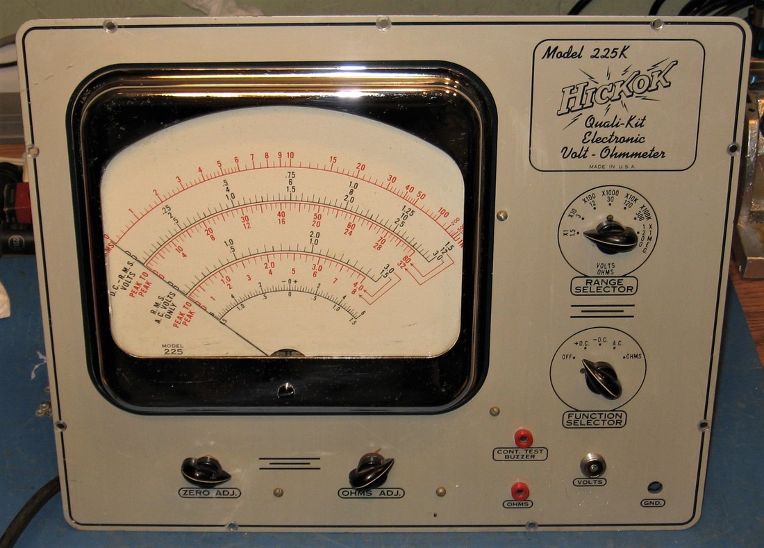
I picked up this Hickok 225K because I wanted a large analog meter that was easy to read, and I think this is about as big as they get. It's got a 9" meter movement and this one was sold as a kit, hence the "K" on the model number. It's around 60 years old and I found the kit listed in a 1960 Hickok catalog. The copyright date of the manual I purchased is 1956, but the schematic inside is dated 1953. The manual refers to pin jacks for the test leads but this unit has banana jacks so it may be from a later production run, or someone swapped them out.
|
The meter movement is in good shape, but the unit needs to be restored. Unfortunately it was missing the original AC/DC probe so I will have to make one. The only other missing part is the banana jack for the ohmmeter ground, but I found a replacement in a parts bin.
The original probe consists of an inline 560K ohm resistor used for DC measurements and a SPDT switch which bypasses the resistor when measuring AC. Pretty simple. I made a replacement probe which is detailed at the bottom of the page. |
|
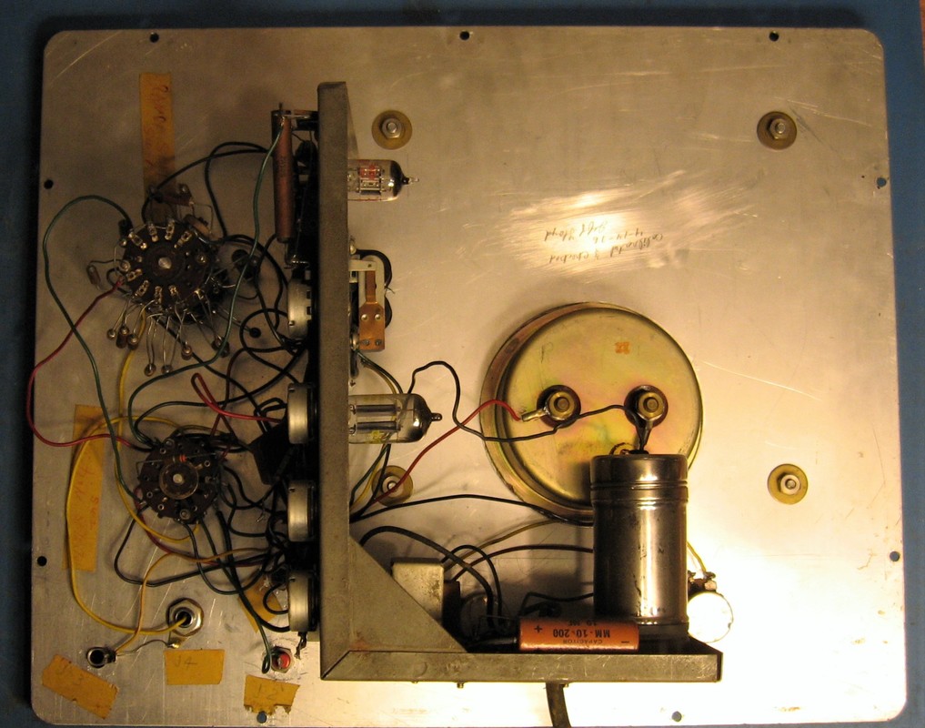
A look at the back of the front panel. The VTVM circuits are on the vertical part of the chassis and the power supply is on the horizontal portion. The silver can is a D-cell battery holder.
The first task was to rebuild the power supply section because there was a large puddle of wax under the power transformer, so it was obviously get pretty warm. I left the selenium rectifier in place but replaced it in circuit with a silicon diode. The old 10uF filter cap was also replaced as were two out-of-tolerance resistors (R24 and R25). The manual says the B+ should be around 170VDC and the silicon diode was providing about 184VDC out so I upped the value of R24, the 2.2K resistor, to 8.2K to bring the voltage back down. |
|
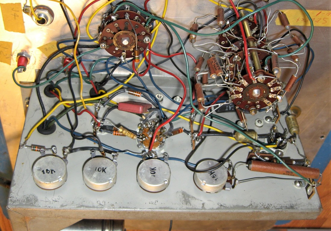
A closeup of the electronics. There are two bad .025uF capacitors, plus several out-of-tolerance carbon composition resistors, and there's also a .05uF "Black Cat" molded capacitor that tested OK but was replaced anyway because of it's age.
It looks like someone has been monkeying around in here since there is a 30K resistor connected on only one end and a 15K resistor added in series with a control wiper. I guess now I'll have to check all the wiring against the schematic. Some of the soldering is not very good either so that needs cleaned up. Both the 12AU7 and 6AL5 tubes checked good and the switches and pots were cleaned with Deoxit and contact cleaner. |
|
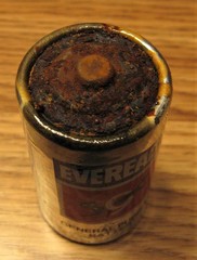
Seems every time I buy a piece of vintage gear that uses batteries this is what I find inside. Does anyone ever take old batteries out of stuff? I'm pretty sure this EverReady's 9 lives are all used up. Fortunately it did very little damage inside the battery holder, just a little corrosion in the bottom.
|
|
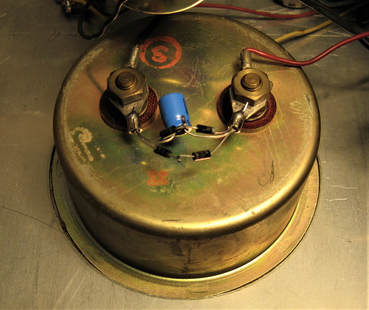
The meter needle bangs off the end stops every time I go from zero to full scale or vice versa, for example when using the ohmmeter, so I added a 100uF electrolytic capacitor across the meter terminals to damp the needle's movement.
I also added protection diodes across the meter. I had to use two diodes in series on each leg because a single diode clips the full scale voltage across the meter, only allowing the needle to get to about 3/4 of full scale. |
After our move I put the 225K back on the service bench and went through the calibration again because I was having problems getting all the ranges calibrated. If I calibrated the DC volts using a 1.5 volt battery following the instructions exactly (calibrating the meter to the voltage "printed" on the battery) then the calibration was reasonably close on all scales except the 3-volt scale used during calibration. The 3-volt scale was off because a 1.5 volt battery is really 1.6 volts when new. But if I calibrate the meter by setting the voltage to 1.6 volts then all the scales are off except the 3-volt scale. This had me scratching my head until I discovered I missed an out of tolerance precision resistor in the voltage divider. Once I replaced it then I was able to get all ranges to calibrate reasonably well.
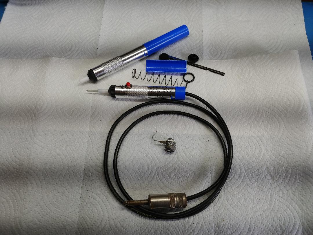
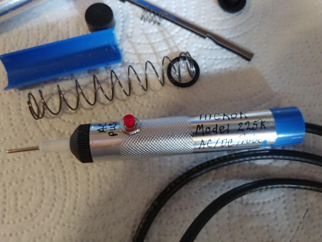
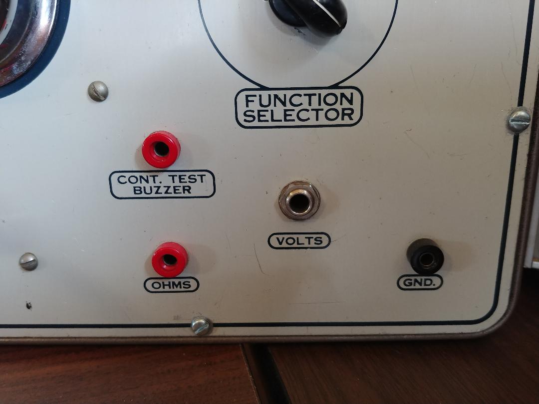
I made a replacement probe from a cheap solder sucker. The first photo shows a solder sucker, the parts removed, and the completed probe. I didn't have a small slide switch on hand for the AC/DC switch so I used a push button. Normally the probe measures DC volts, but press and hold the button and it can measure AC voltage. On this VTVM Ohms is measured by a separate probe plugged into the front panel Ohms jack so the new probe is only for DC and AC volts. I changed the front panel Volts connector to a 1/4" phone jack so I could easily plug and unplug the probe.
Last update 9/25/2019

