
Converting a B&K Oscilliscope into a Component Signature Curve Tracer
A signature, or component tracer is a type of curve tracer for testing various electronic components in and out of circuit, and it's a very handy tool for troubleshooting. This tracer was created by converting a 1980's vintage B&K model 1403A oscilloscope using the curve tracer schematic available from Mr. Carlson's Lab on Patreon. The schematic and PCB files are available to his subscribers.
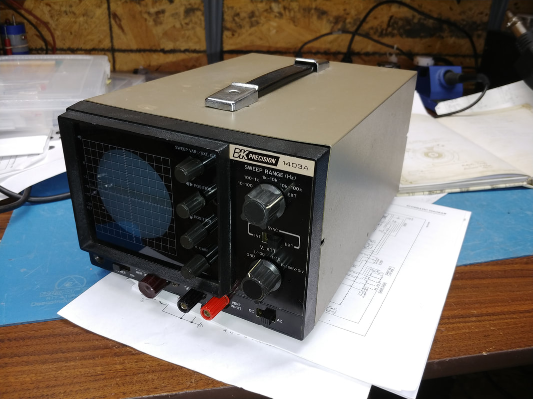
This instrument is a transistorized general purpose compact 5MHz oscilloscope and B&K produced several similar models including the 1403, 1403A and the 1405. It doesn't have the greatest of specs, but it doesn't need them for the component tracer, and it's compact size is perfect for the job.
This instrument is a transistorized general purpose compact 5MHz oscilloscope and B&K produced several similar models including the 1403, 1403A and the 1405. It doesn't have the greatest of specs, but it doesn't need them for the component tracer, and it's compact size is perfect for the job.
A word of warning concerning transistorized scopes like this: there is VERY HIGH VOLTAGE inside. Even though the unit may be transistorized, the CRT is still a tube and there are potentials as high as 1400VDC inside. If you're not experienced working on equipment like this then DON'T! Proceed at your own risk.
|
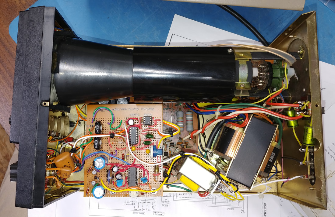
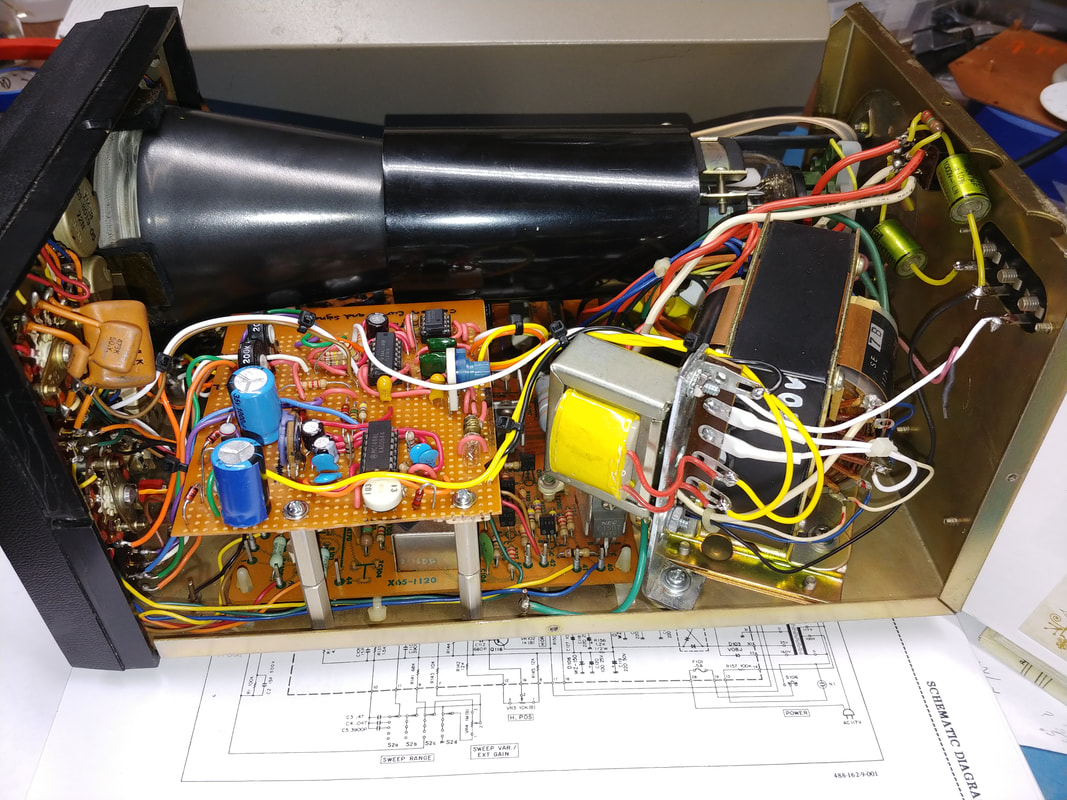
The first step in converting the scope to a tracer was completely recapping it and confirming it is in working condition. Next several components were removed or repurposed on the front panel to accommodate the curve tracer. The EXT Horizontal input jack was removed and the tracer's oscillator level control substituted, and the external horizontal input switch position was connected to the tracer board's Horizontal Out.
The AC/DC switch was rewired to serve as the Lo / Hi current selector and the Vertical Input jack was rewired as the tracer probe input. The tracer board's Vertical Out was connected to the scope's attenuator switch and on to the vertical input. The Z-Axis input terminal on the rear was disconnected and replaced with the Meter Out line, which allows connecting a DVM as a digital readout of the oscillator voltage level. |
The modifications to the scope are reversible, no new holes were drilled or any other changes made that couldn't be undone if desired. The only inputs to the scope circuitry after the mods are from the tracer PCB, but basic scope functions still work and can be used for verifying proper tracer operation. Building the circuit on prototyping board turned out to be a bit time consuming, but the conversion itself was fairly straight forward.
|
Although there are PCB layouts for both the tracer PCB and a power supply on Patreon, this tracer was hand wired on prototyping board because I wasn't setup to make PCBs at the time. The ICs in the picture are op amps and a dual +/- power supply regulator. The board's input power comes from a separate power transformer which was added near the scope's xformer.
|
|
The tracer PCB is attached using standoffs mounted in existing chassis holes. Likewise, the tracer power transformer is also mounted using an existing hole.
The tracer power supply is +/- 17.5VDC. The oscillator runs at 1KHz with a max output voltage of about 15.5V and is adjustable via a front panel gain control. There are two current ranges: Low = 1ma and High =10ma. |
|
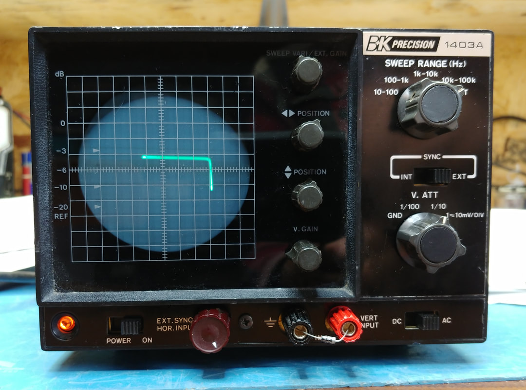
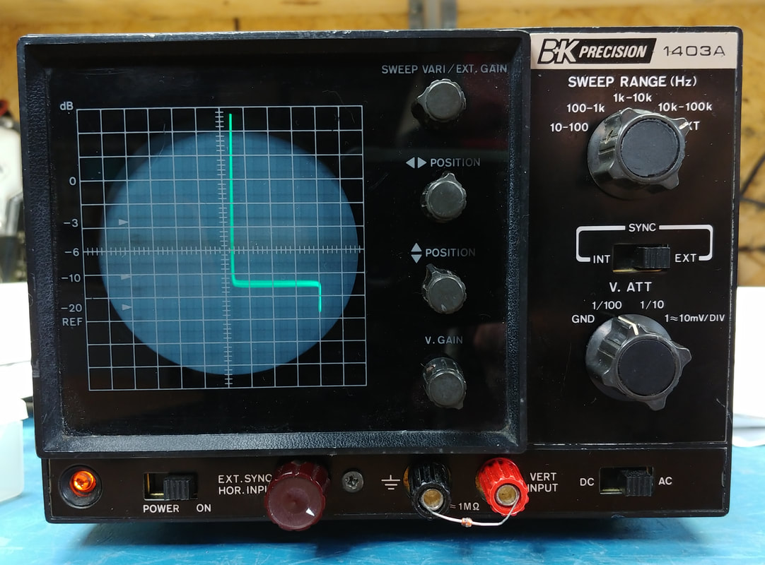
The signature for a diode creates a "knee" (forward and reverse). This particular diode is a 1N4007. Basically, I'm looking for a good, sharp knee. The orientation of the curve depends on which way the leads are connected.
Transistor junctions can likewise be checked by the tracer. |
|
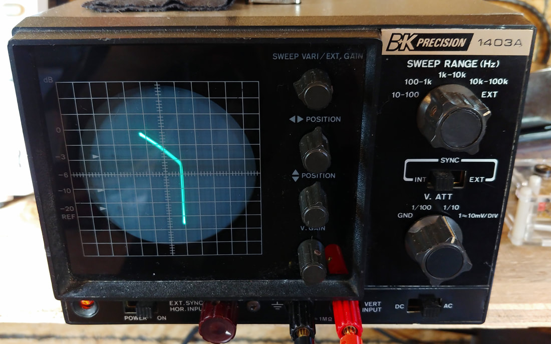
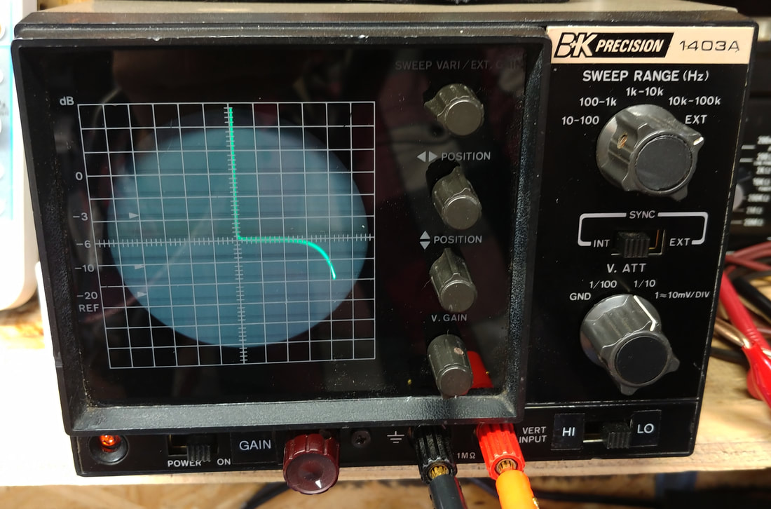
A Zener diode not only has a forward conducting knee like a normal diode, but its signature also has a second knee at the zener's breakdown voltage where it begins to conduct in the reverse direction. The tracer can test Zeners up to 15 volts.
|
|
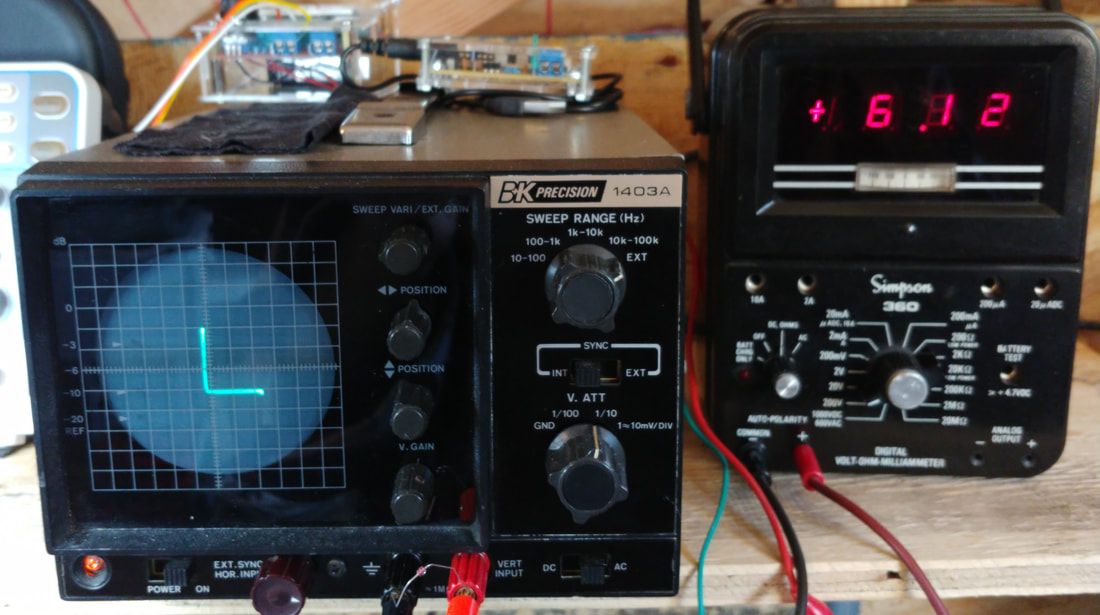
Here is an example of using a digital readout with the tracer. The oscillator gain is adjusted to where the zener's reverse breakdown knee is just beginning to turn. The Simpson 360's display shows this is a bit over 6 volts (the diode is a 6.2 volt zener).
|
|
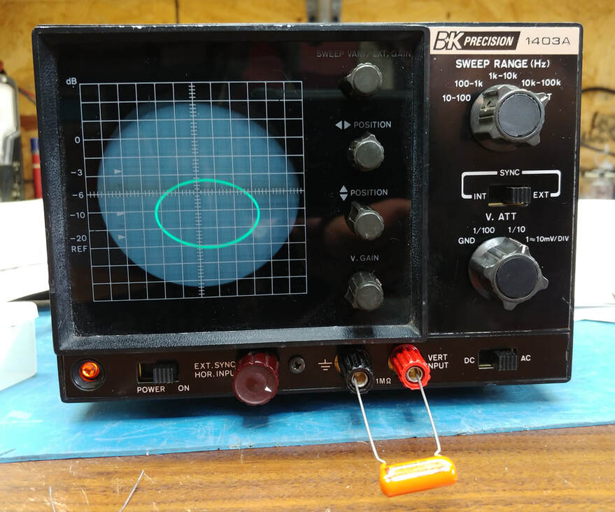
The signature of a capacitor, or an inductor, is an ellipse. How open the ellipse is depends on the value of the component. If there is measurable resistance in parallel the ellipse will be tilted.
|
|
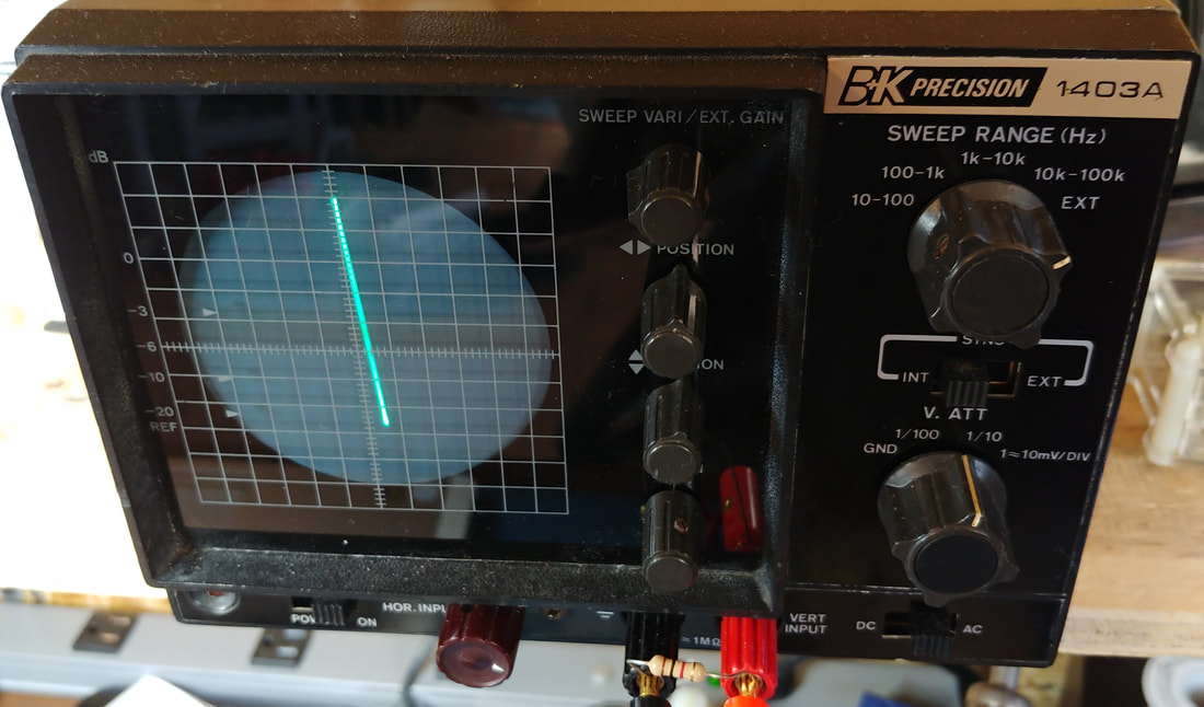
A short displays as a vertical line (zero ohms). A resistor is a line that is tilted from vertical. The degree of tilt depends on the resistance. This is the signature of a 1Kohm resistor.
|
|
This is the signature of a damaged base-collector junction in a 2SC945 transistor from the driver board of a 1970's Luxman R1040 receiver. The output was accidentally shorted which blew output and driver transistors, and damaged this pre-driver transistor.
|
|
Another example of a less than perfect part. The reverse breakdown knee of this zener diode is not very sharp. This is an unmarked part from an old bag of discount components. Probably a factory reject.
|
Page created 2/11/2020
Last updated 4/19/2021
Last updated 4/19/2021
