
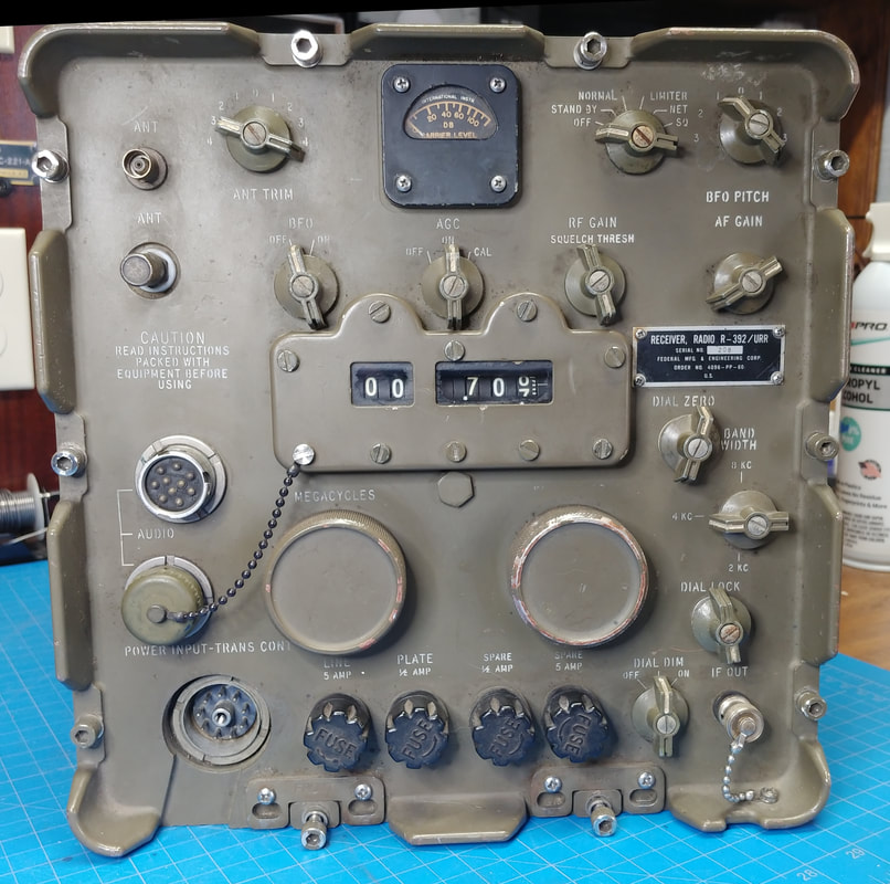
Military R-392/URR HF Receiver
The R-392 is a rugged receiver designed for vehicular use. It covers 500KHz to 32MHz in 32 bands and has a mechanical digital readout. It's from the 1950's and 60's era and is part of the AN/GRC-19 portable transmitter-receiver setup. I just refer to it as a jeep radio since the manual shows it mounted in the rear of an Army jeep and it qualifies as a "boat anchor", weighing in at 52 lbs not including accessories. It normally operates on 28-volts DC, but according to the operators manual can be run on 25-30 volts, and requires 3-amps. Even the tube plates run at this voltage and I've never owned a tube radio that uses a lower B+ voltage.
|
This R-392 is another hamfest find I couldn't pass by. I had one of these years ago that I sold and later regretted letting it go, so when this seller offered me a good deal which included a couple of Power One 28-volt 3-amp power supplies, an original power input connector, and two U-77 audio connectors, all at one amazing low price, I couldn't say no (my wife wasn't there).
This particular receiver was manufactured by Federal Manufacturing & Engineering Corp. and the contract number is dated 1960. That would make it right at 61 years old now. |
|
|
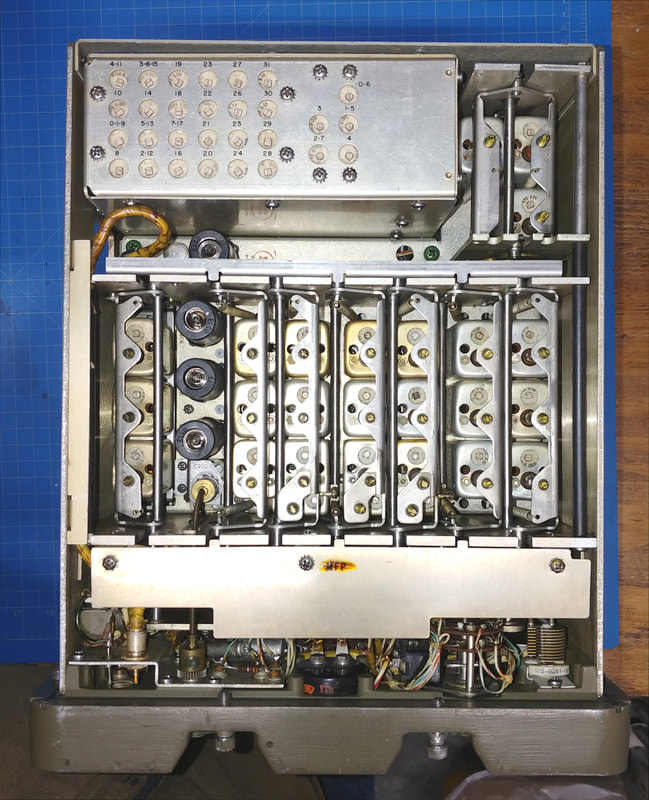
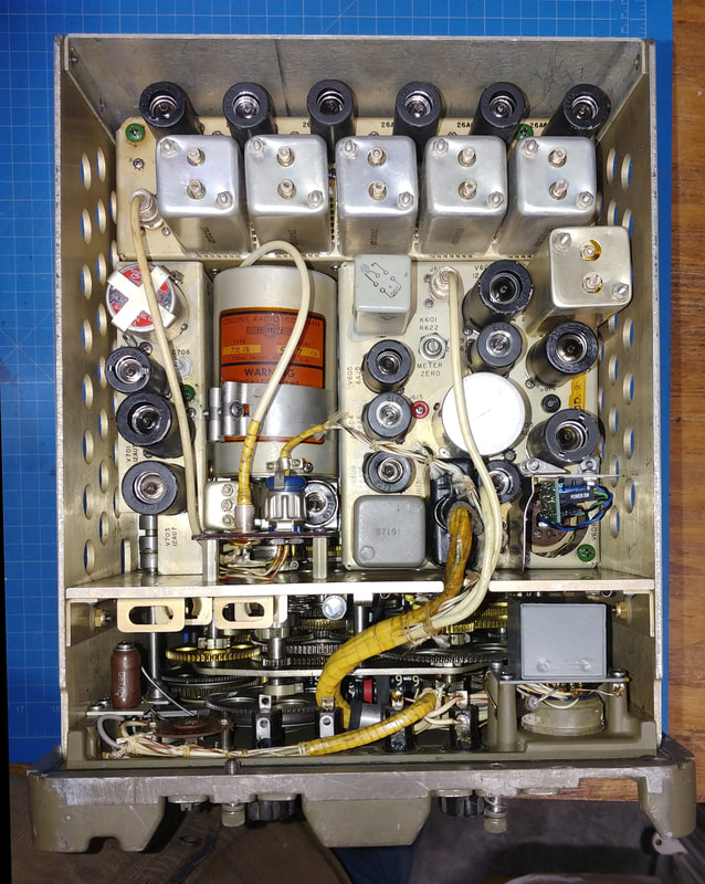
The radio is a sealed, immersion-proof unit so the inside is pristine. It's all complete except the 26A7 audio output tube has been pulled and replaced with a solid state audio amp PCB. This is a fairly common mod, and is reversible if desired. I think the 26A7 produces more excess heat than any other tube in the set, eating up 16-watts of filament power while only putting out a measly 200mw of audio, so it's a good candidate for a solid state conversion.
The only other missing items are the two tube pullers, the right-angle screwdriver and the bristol wrench. Tools just never seem to get put back where they belong.
The only other missing items are the two tube pullers, the right-angle screwdriver and the bristol wrench. Tools just never seem to get put back where they belong.
|
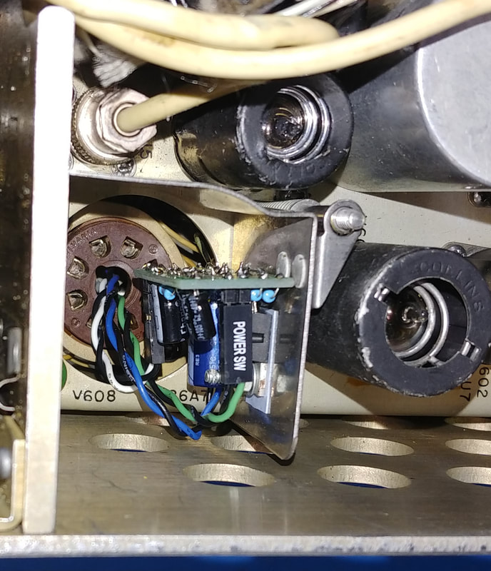
This is a closeup of the audio mod that replaces the 26A7 tube. Not sure who made this audio conversion. I vaguely remember someone selling an audio mod years ago, but I can't find any documentation on it now.
|
|
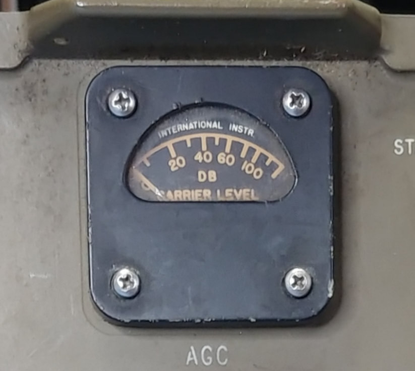
I've seen some R-392 receivers that had their original radioactive, glow in the dark, Carrier Level meters removed when they were sold as surplus, but this one still has the meter with the radium dial. I confirmed it's still radioactive with my Lionel CD V-700 geiger counter, and it reads about 1.2 mr/hr (700 c/m) with the probe placed right up against the glass. As a comparison the check source on the counter reads 1.5mr/hr (1000 c/m). At about six inches to a foot away you can't tell it from the background radiation.
|
|
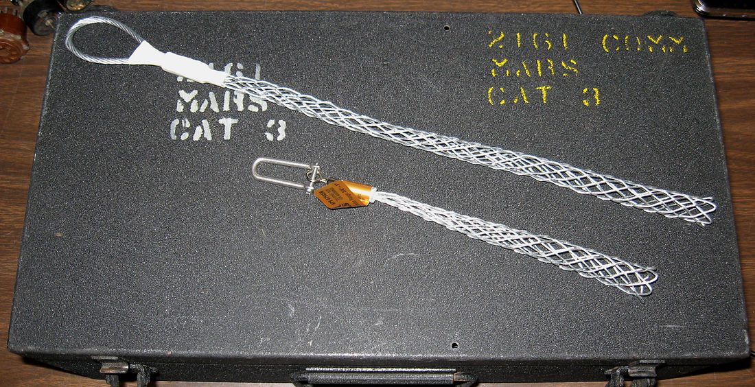
Tube pullers are a necessity to get some of the tubes out of the tight spaces in this radio, but at the time I couldn't find any vintage ones. However I did find the same thing, only different. They are called some variant of cable socks, cable grips or cable pullers, but work the same way as a tube puller. I purchased a Klein 3/4" - 1" cable puller that I was able to pull 9-pin tubes with. For the smaller 7-pin tubes I had to resort to ordering a cable grip online. They're not quite as good as real tube pullers but they work in a pinch.
|
|
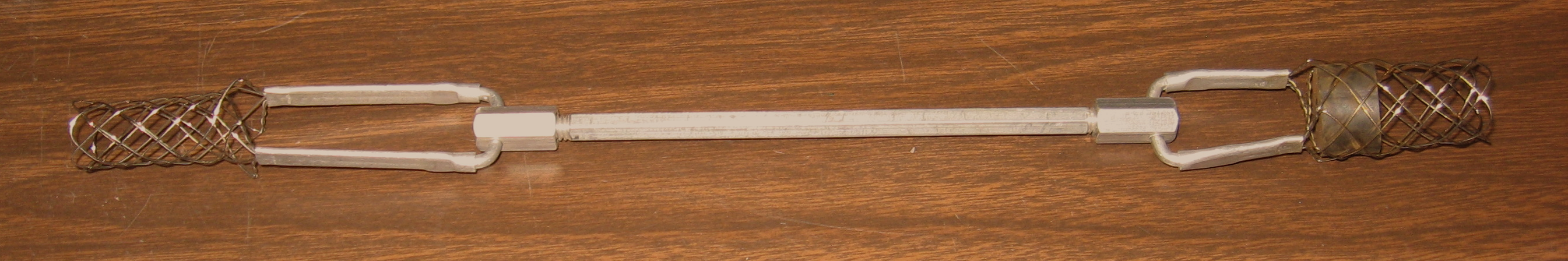
Of course, after purchasing the cable pullers, I actually found a vintage tube puller for both 7-pin and 9-pin tubes.
|
A Power Supply for the R-392
The R-392 requires 28VDC at 3 amps from an external power supply, at least according to the manual. But in reality it needs more than 3 amps at power on with cold filaments.
Power One Supply
|
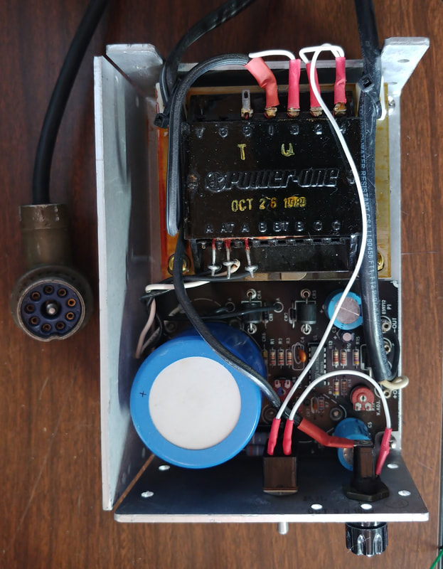
This is one of the Power One brand power supplies (PS) that I got with the radio. I modified it by adding a power switch and line fuse to the chassis. It produces 28-volts (adjustable) at 3-amps, but this one is set to 27.5-volts. The PS sensing lines are tied directly to the output pins and at power on (when the filaments are cold) it drops the output voltage to about 1.5-volts, and as the filaments warm it raises the output in step, and within a minute or so it's up to full voltage and the filaments are all warmed up. Then I can finally switch the radio from Standby to Normal operation. I tried both of them and they behave the same so the radio pulls more than 3-amps at power on with cold filaments. And the supply starts getting a bit warm after the radio has been on for twenty or thirty minutes. I thought about adding the second supply in parallel to share the load, but balancing them would be a pain, and then I found another cheap supply online.
|
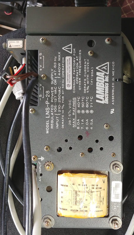
Lambda LNS-P-28 Supply
|
|
This Lambda supply seemed like just the ticket when I bought it. It's rated at 28-volts (adjustable) at up to 8-amps. But it has been nothing but a pain so far.
When I received it and hooked it up for a test I immediately noticed that it was not stable: the voltage drifted higher and higher as it warmed up. So I put about a 3 amp load on it, and instantly blew two diodes in the bridge rectifier. The bridge consists of two sets of dual diodes in TO-3 transistor-style packages, and replacements cost more than the PS, so I installed a 15-amp block-style bridge rectifier instead, and pulled both TO-3's. When I powered it up again it was still drifting so I loaded it once more, and blew one of the pass transistors, which shorted from emitter to collector. Not good as the shorted pass transistor was putting 35-volts loaded (48-volts unloaded) on the output. I replaced the Lambda proprietary TO-3 transistor with a 2N3055, which worked fine and finally got the supply running solid under a load. Apparently the pass transistor was the real issue, slowly failing as it warmed up and that was causing the voltage drift.
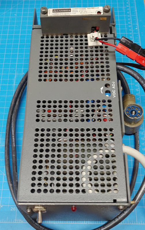
To protect my R-392 from any chance of an overvoltage I modified the PS by adding a Lambda overvoltage crowbar module I found in a parts drawer, along with a 5-amp fuse for the crowbar to blow to disconnect the voltage from the radio. I also added a power switch and fuse holder to the AC input, and an LED for a power on indicator. The PS already has another internal fuse on the DC side, but it's a 20-amp fuse that never blew during any of the troubles I had, so I replaced it with a 6-amp fuse to set it to a more reasonable max current. While adjusting the crowbar voltage yet another of the Lambda TO-3 pass transistors failed with a short. It was replaced with another 2N3055. There's only one of the Lambda transistors left in circuit so I will replace it too, out of an abundance of caution, but first I need to buy more 2N3055 transistors.
I also added a digital voltmeter module on the output so I can monitor the voltage in real time, because I no longer trust this supply, even though it seems stable now, and has overvoltage protection installed to protect my radio.
If I had to do it over again, I would never have bought a Lambda supply. There aren't any free manuals or schematics available online and all the parts have proprietary part numbers. And the original parts are way too expensive.
When I received it and hooked it up for a test I immediately noticed that it was not stable: the voltage drifted higher and higher as it warmed up. So I put about a 3 amp load on it, and instantly blew two diodes in the bridge rectifier. The bridge consists of two sets of dual diodes in TO-3 transistor-style packages, and replacements cost more than the PS, so I installed a 15-amp block-style bridge rectifier instead, and pulled both TO-3's. When I powered it up again it was still drifting so I loaded it once more, and blew one of the pass transistors, which shorted from emitter to collector. Not good as the shorted pass transistor was putting 35-volts loaded (48-volts unloaded) on the output. I replaced the Lambda proprietary TO-3 transistor with a 2N3055, which worked fine and finally got the supply running solid under a load. Apparently the pass transistor was the real issue, slowly failing as it warmed up and that was causing the voltage drift.
To protect my R-392 from any chance of an overvoltage I modified the PS by adding a Lambda overvoltage crowbar module I found in a parts drawer, along with a 5-amp fuse for the crowbar to blow to disconnect the voltage from the radio. I also added a power switch and fuse holder to the AC input, and an LED for a power on indicator. The PS already has another internal fuse on the DC side, but it's a 20-amp fuse that never blew during any of the troubles I had, so I replaced it with a 6-amp fuse to set it to a more reasonable max current. While adjusting the crowbar voltage yet another of the Lambda TO-3 pass transistors failed with a short. It was replaced with another 2N3055. There's only one of the Lambda transistors left in circuit so I will replace it too, out of an abundance of caution, but first I need to buy more 2N3055 transistors.
I also added a digital voltmeter module on the output so I can monitor the voltage in real time, because I no longer trust this supply, even though it seems stable now, and has overvoltage protection installed to protect my radio.
If I had to do it over again, I would never have bought a Lambda supply. There aren't any free manuals or schematics available online and all the parts have proprietary part numbers. And the original parts are way too expensive.
This radio is operational and the alignment looks good, but it appears to still be running on its original capacitors. The ones I could see are Vitamin Q caps, which were good quality in their day, but after 60 years it's probably a good idea to go through the radio checking all of them for leakage. I've also read that some of the original silver mica caps start acting up with age, too. I also notice the S-meter is not working properly, so I'm sure there are issues, but I need to find the time to get it on the bench.
Page created 5/25/2020
Last update 2/24/2021
Last update 2/24/2021
