
Restoring a 1937 Sears Silvertone Model 4465 Tombstone
I did this restoration for a friend and it was their grandfather's radio. It wasn't in great shape, the chassis had a lot of surface rust, the cabinet had been stripped bare, and had some missing veneer and a big water stain on one side. Unfortunately, I forgot to take a photo of the cabinet before I started working on it.
|
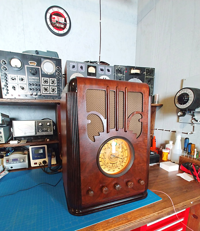
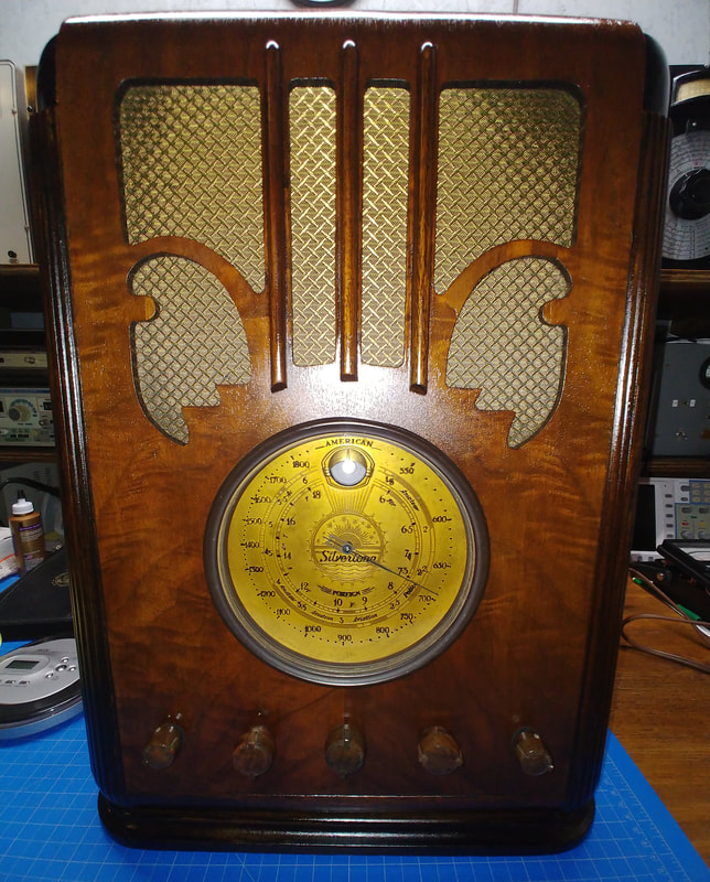
The completed radio sitting on my new workbench, the first project to be completed on it. I really came to like this set as I restored it. The cabinet is trapizoidal, wider at the bottom than the top, and the front slopes back ever so slightly. The brass dial plate is nicely decorated too, and the radio's audio is very mellow and pleasing. In the Riders documentation there is a modification for a phono input, which I added. I used it to connect a CD player and listen to old radio shows, and they sound great on this old timer. I did find the line output of my portable CD to be a bit low for the set, so I used the earphone jack instead and it worked a treat. I made a cable specially for the radio with internal resistors to safely combine the left and right channels into a mono input signal. I could listen to it all day (if my wife would let me).
|
|
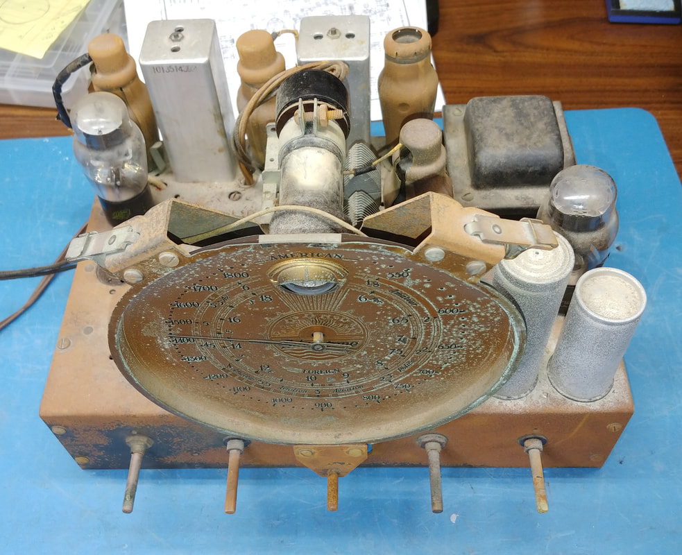
The chassis has a LOT of surface rust. The owner said it had been in Florida before and maybe the salt air did it. And the beautiful brass dial also has its share of corrosion. To keep the repair costs down I did what I could easily and quickly do to get rid of as much rust as possible, but the chassis would probably need painted to get it all.
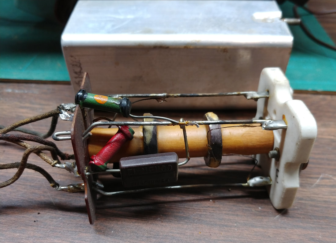
There are 3 disintegrating grommets supporting the tuning capacitor that will have to be replaced as well, and the rubber chassis mounts are gone, so I'll need those too. I also noticed the vernier tuning is seized up so I'll have to clean and lube that to free it, and replace the dial string while I'm at it. |
|
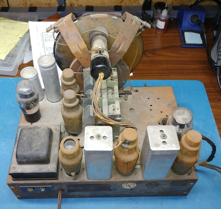
All the goat tube shields are corroded. And the transformer needs repainted. The insulation on the wiring harness to the eye tube is rotten so I'll need to make a new harness using new cloth-covered wire. Same goes for the speaker harness, it is dry rotted too.
|
|
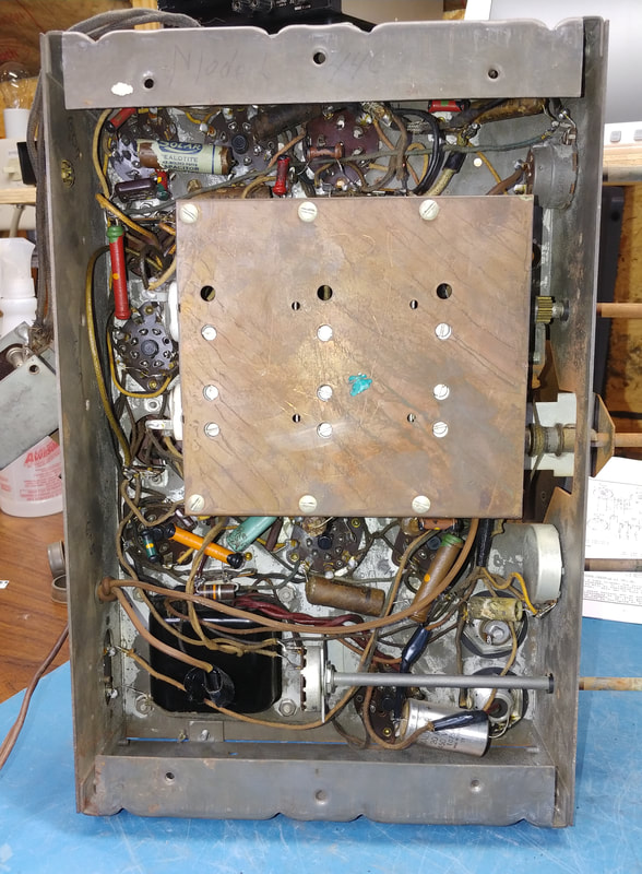
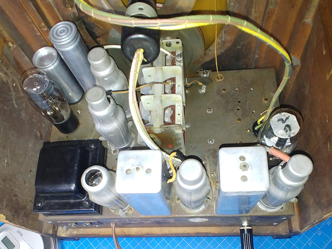
Under the chassis all the paper caps and the two electrolytic filter capacitors need replaced. All but a couple of the resistors have drifted high over the decades and need replaced as well.
Of course the set is going to need a complete alignment. The alignment points consist of the trimmer adjustments visible through the holes in the copper shield, plus the two trimmer capacitors facing, and accessible, through the rear panel, and the trimmer adjustments on top of the two IF cans. |
|
There are also resistors inside the last IF can that need replaced along with the dry rotted grid cap wire. Plus a connection or two to the eye tube comes out of It.
|
|
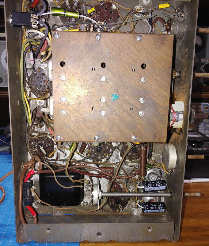
A top view of the completed chassis. Among other things, I also replaced the dry rotted shielded lead to the grid of the first AF amp. The new wiring harnesses for the speaker and eye tube are also shown. And I repainted the tube shields with silver leaf paint and then rubbed them down some to disguise the paint job. The only tube that needed replaced was, of course, the 6G5 eye tube. Prices for a NOS American-made eye tube are astronomical these days.
|
|
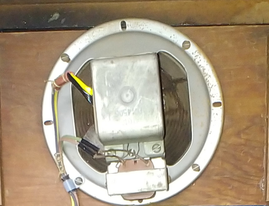
Some speaker cone cracks were repaired and the wiring to the field coil repaired. It was shorting to the frame due to dry rotted insulation. The speaker harness was strapped to the speaker frame to remove all stress from the field coil and output transformer connections.
|
|
Under the chassis all the bad caps and resistors have been replaced. I also added a fuse holder and fuse to the AC line for safety. Of the two original electrolytic caps one was rated at 450 volts and the other at 350 volts, which is fine after warm up when the B+ settles down to a bit over 300 volts. But I discovered that at turn on the high voltage surges to 475 volts across both caps. The surge only lasts about 5 seconds but I'm still kind of surprised the 350-volt cap could handle that much over-voltage. I replaced both with 500-volt capacitors just to be safe.
|
A final look at the completed radio. Hope I still look this good at 83.
Page created 10/05/2020
Last edited 10/06/2020
Last edited 10/06/2020
