Restoring a Hickok Model 19X Crystal Controlled Microvolt Generator
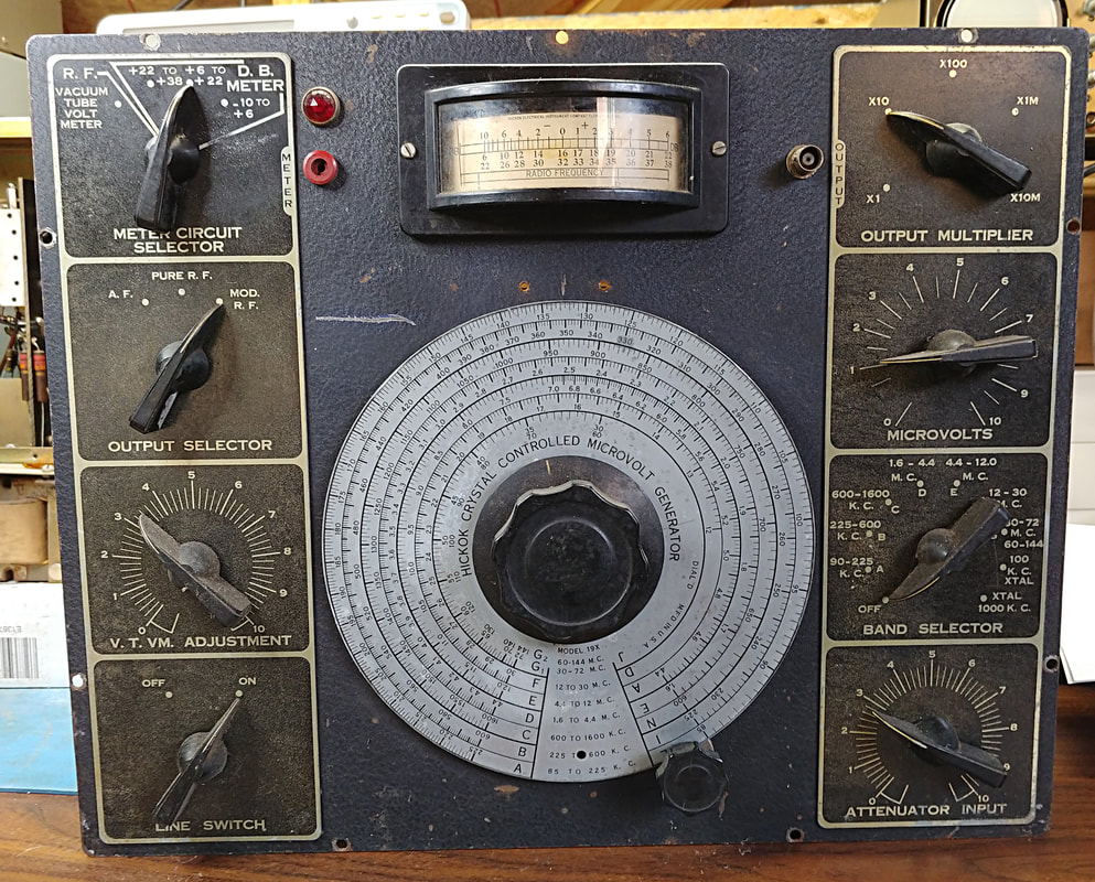
I found this signal generator at a hamfest for free. Couldn't pass that up so home it came and it's been sitting in a corner awaiting its turn on the bench. It dates to circa 1940 and is in good condition for its age.
|
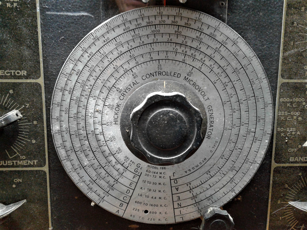
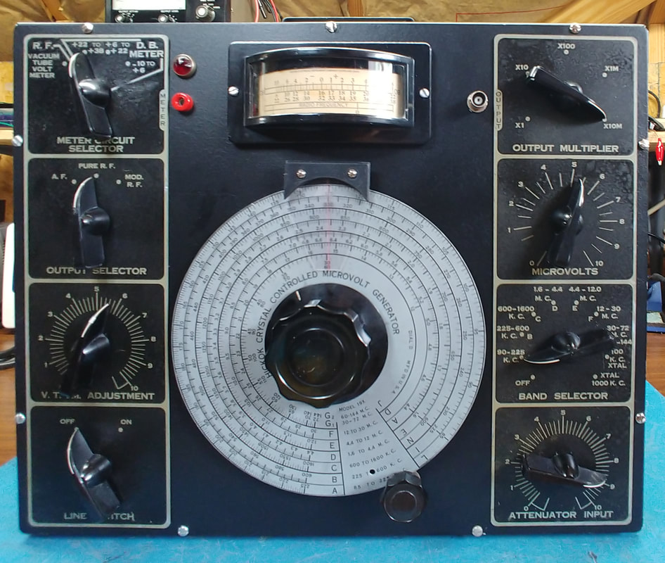
Close up of the frequency dial scale plate. It's just a bit tarnished and only has a minor scratch or two. Identifying information for the generator is on the dial, and there's a plate with the model and serial number hiding on the bottom of the case. It's a model 19X and I found a manual for a 19XD which matches this unit. The only difference I can see with the "D" model is a different knob style.
|
|
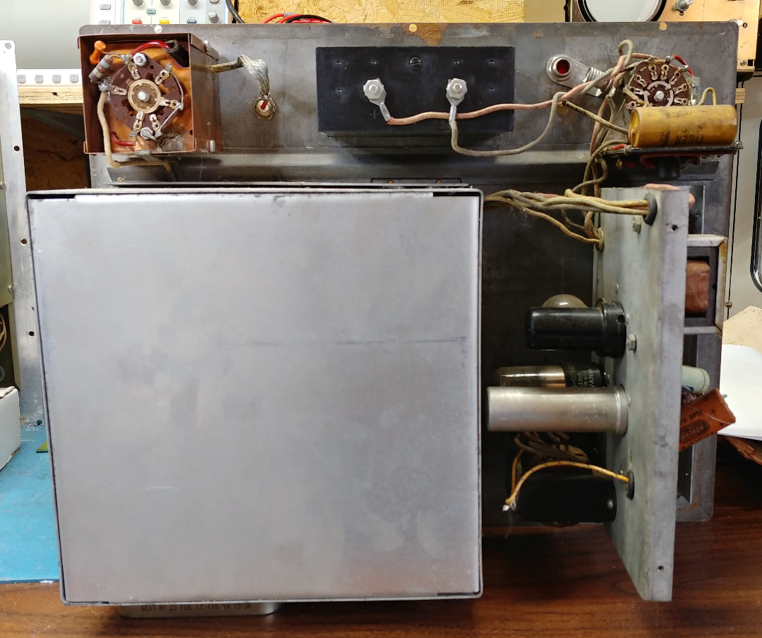
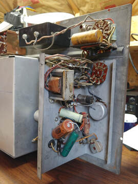
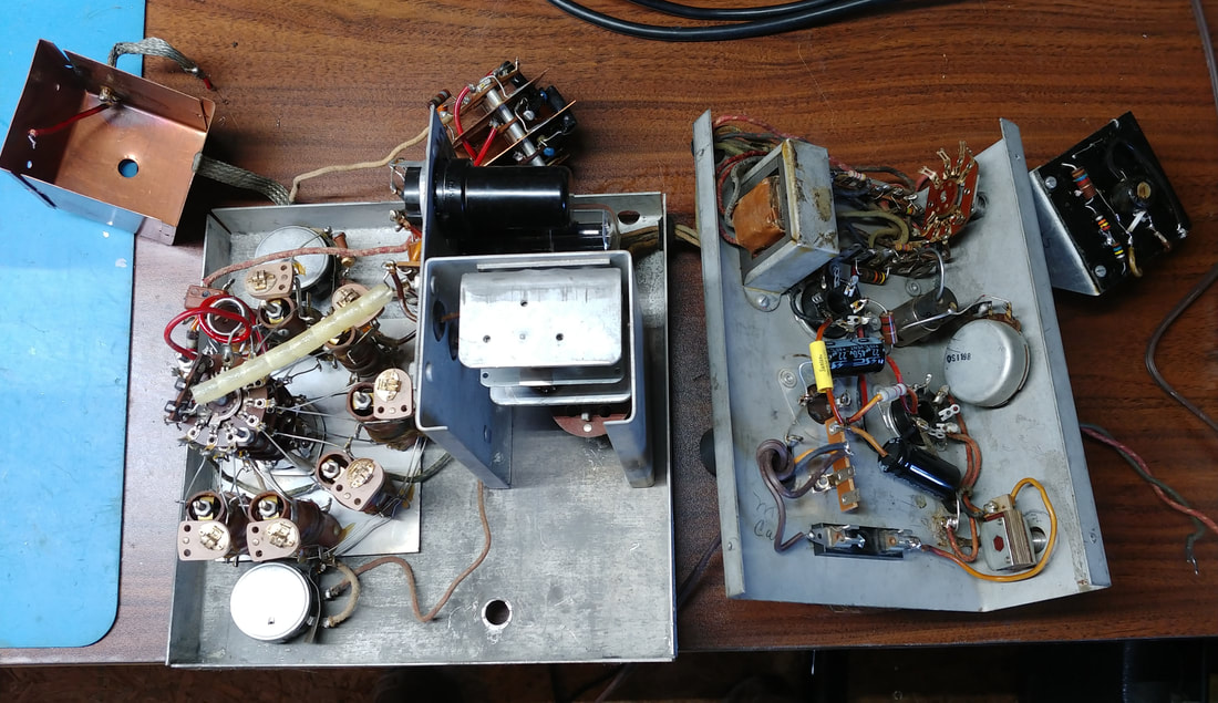
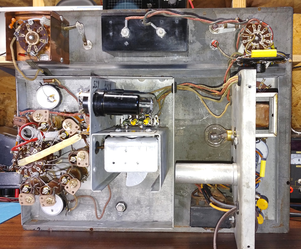
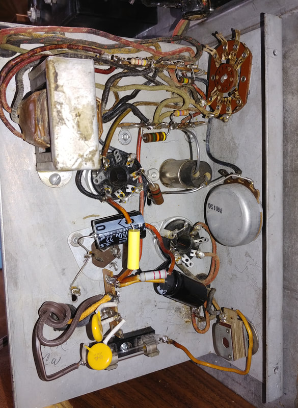
Inside the shielded compartment containing the audio modulator and power supply. Someone changed a filter capacitor by unhooking the wires and soldering them to the replacement and letting everything just hang loose. There are also leaky paper capacitors tied from both sides of the AC line to the chassis that must be replaced.
|
|
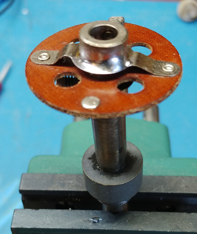
One big problem with the generator was the dial was slipping and couldn't be kept in alignment. The reason turned out to be the shaft coupler between the dial and tuning capacitor. The two-piece crimped mount on one side of the coupler was not crimped tight enough and was slipping when the tuning cap hit fully open or fully meshed. The fix was to solder the two pieces together. This might have been one reason this unit was sitting in the grass with a free sign on it.
|
|
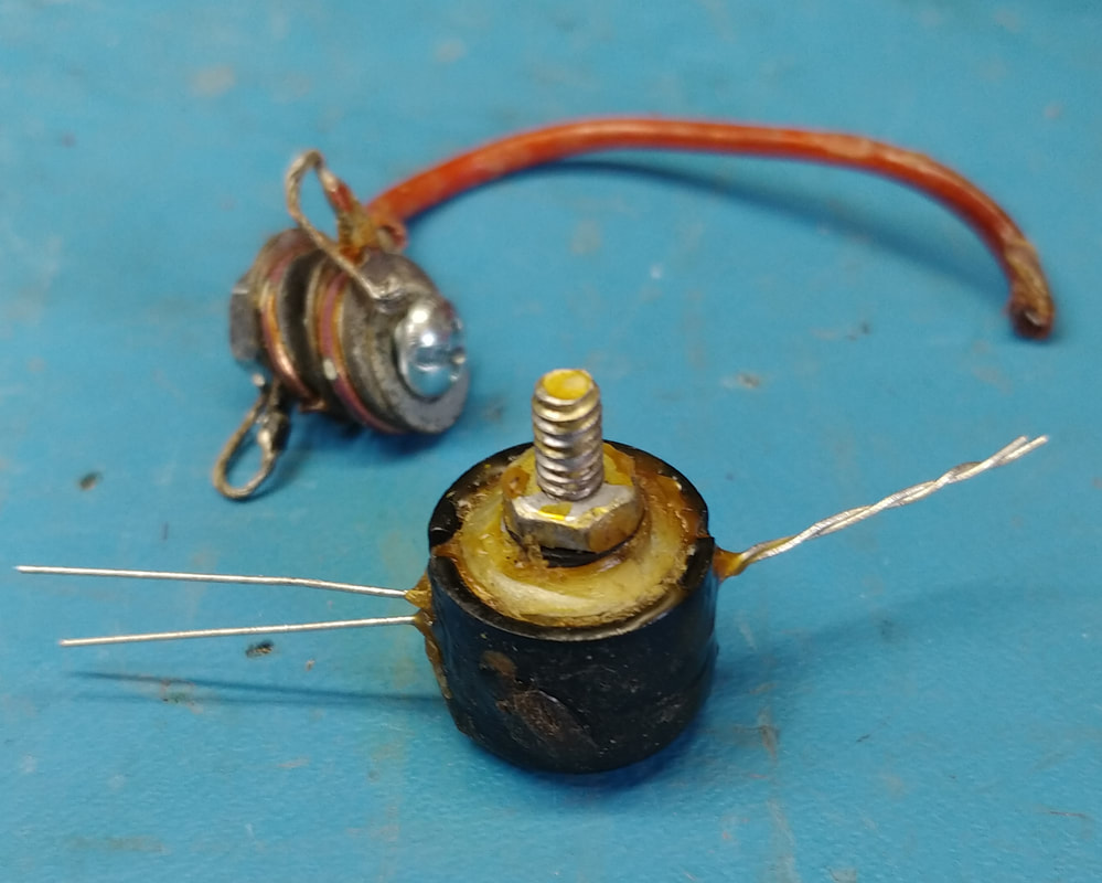
There's a copper oxide rectifier assembly in the voltmeter section that is used by the output meter. The two diodes in it are shown on the schematic if you look close, but are not identified in the parts list. The only other reference to them is in the theory section of the manual. I rebuilt the assembly with two germanium diodes and the old copper disks are shown on the screw beside the rebuilt assembly.
|
|
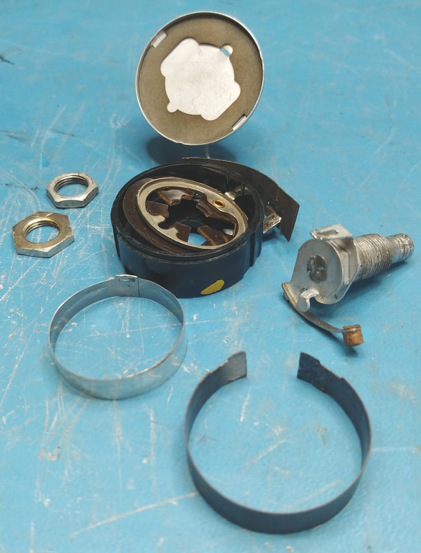
Just when I thought I was finished I found one last problem while checking the attenuator section. The Microvolts pot has a bad connection (high ohms) on its low end to ground. Even with the control at minimum there is still about 200-ohms resistance to ground, and the pot is only 200-ohms to begin with, so it's turned into a 400-ohm pot that can only be turned down halfway. I disassembled it and the carbon track has flaked off at the connection to the end terminal. I didn't have a suitable 200-ohm replacement and had to order one. It's now been installed and the Microvolts control works properly, so I'm ready for the alignment.
|
The front panel paint has been refreshed, the dial plates cleaned and coated with clear satin enamel, as was the dial scale, and all the Bakelite was polished. A replacement for the missing dial marker has been created and installed and the Microvolts pot replaced. It's now ready for a final alignment.
The manual's procedure uses a receiver to listen for the zero beat of the generator and a crystal calibrator. I gave it a try and it is very accurate but a bit tedious compared to just using a frequency counter. But I guess they didn't have those back in the day. The alignment went smoothly and it's back in its case now. This will be a handy generator for radio alignments.
Page created 12/23/2019
Last update 7/12/2020
Last update 7/12/2020

