
Lafayette KT-200 Shortwave Receiver
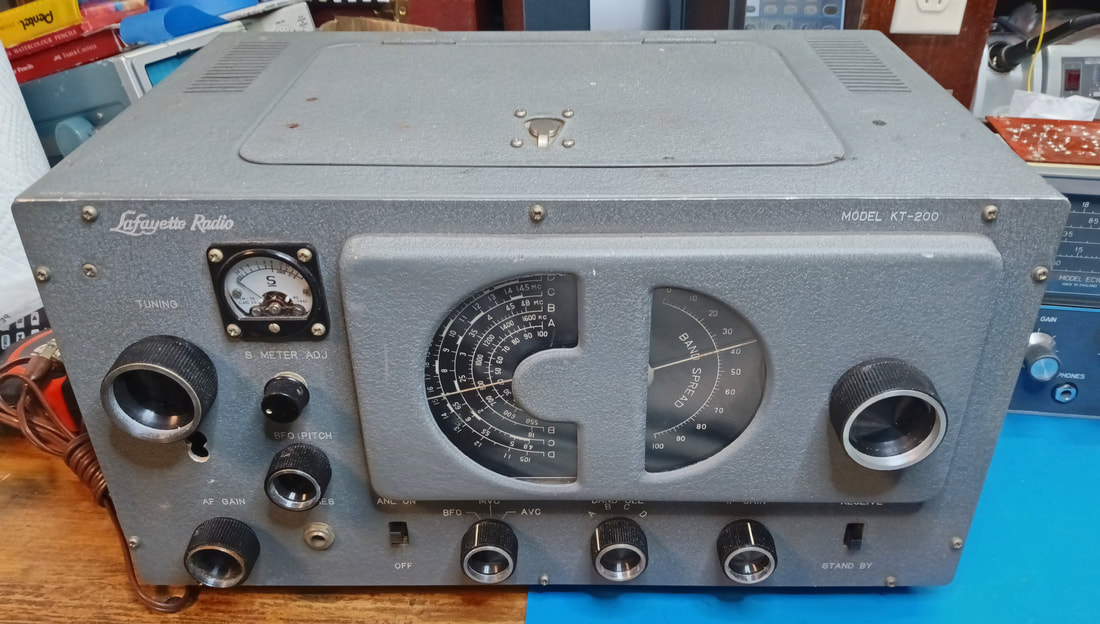
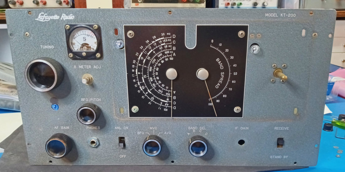
This general coverage communications receiver came out in 1959 and was sold by Lafayette as either a kit (model KT-200) like this one, or as the factory assembled model HE-10. It was also sold by Trio of Japan (Kenwood) as the model 9R-4J. At first glance it might be mistaken for a Hallicrafters S-38, from which it's dial layout is copied, but it's actually a step up. Its frequency range covers 500KC to 30MC and the tube complement is all miniature tubes except for a 5Y3 octal-base rectifier. It also sports an RF amplifier stage, an S-Meter, and a Beat Frequency Oscillator (BFO).
|
This set is a Hamfest find and is in pretty good shape for its age. There's no real rust to speak of, the paint is in good shape, it looks to be complete and unmodified, with a couple of exceptions, and I snapped it up as soon as I saw it.
The exceptions are a double hole someone punched in the front panel right below the tuning dial, and another hole that was added in the back for an RCA jack. Beats me why they punched two holes together on the front. I guess they missed on the location the first time so they did it again. I'll have to get creative to fix or hide this. Someone also drilled a couple of small holes in the top lid to mount something. |
|
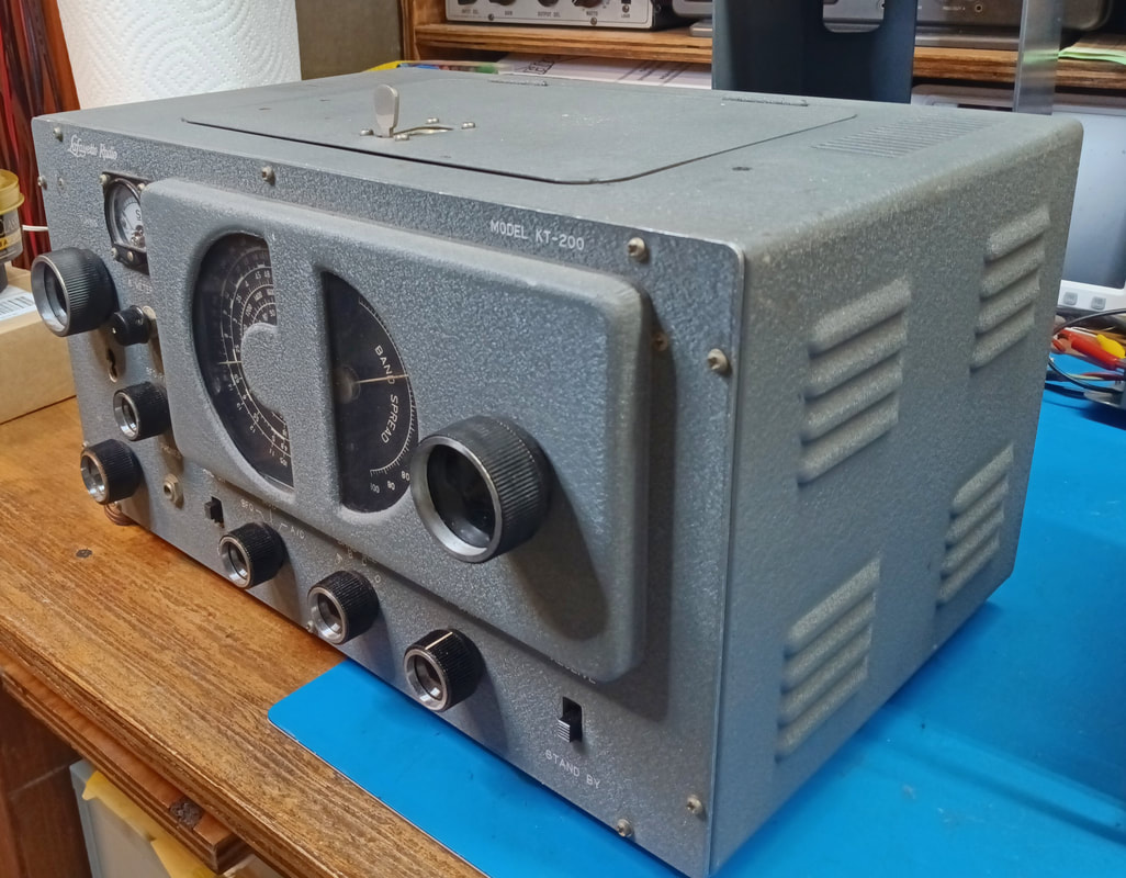
A view from one side shows what a nice retro design it has. It has the looks of a big boat anchor radio, but in a smaller package.
|
|
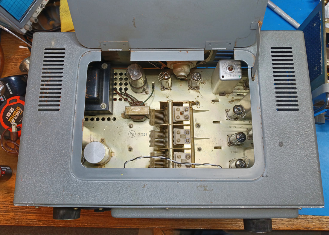
Inside is reasonably clean and it appears to be complete. It should make for a fun restoration. Someone mounted a small speaker to the rear panel, but I'm going to remove it.
|
|
The chassis removed from its cabinet. There's dust on it, plus a few small spots of oxidation here and there, and the tuning capacitor is grimy, but really nothing too bad.
The weighted tuning is a bit stiff and doesn't spin as smooth as it should, so it needs cleaned and lubed. Someone also rewired the panel lamps with wiring that doesn't match the chassis wiring, so it will get replaced. And the top of the power transformer is scratched and needs repainted. |
|
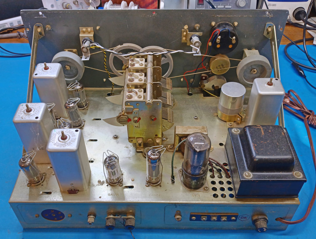
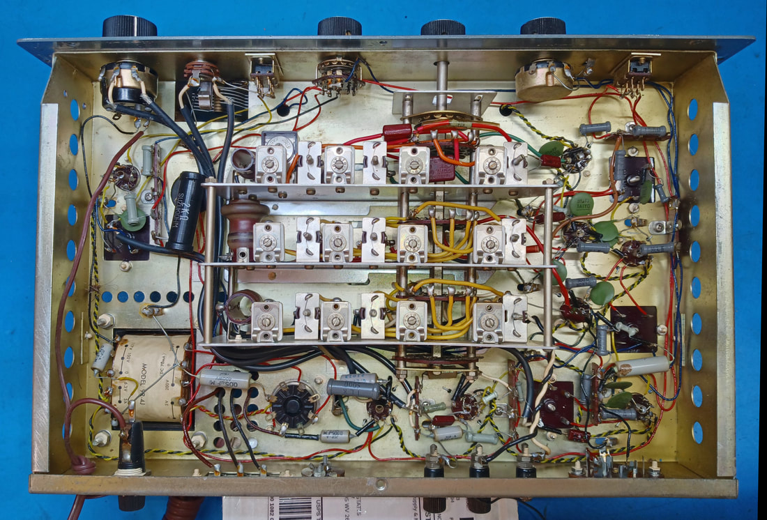
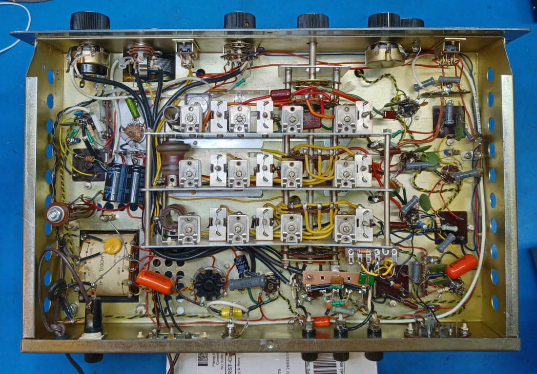
Under the chassis looks to be 100% original. This was a kit radio and whoever built it did a decent job. There's a couple of ground connections that need resoldered, one or two wires were melted by a soldering iron, and the ends of a lot of the chassis wires are stripped back a bit too much. I think the wires were probably stripped OK to begin with, but the heat from soldering caused the plastic insulation to shrink back.
|
The resistors look to be tubular film and all of them check good. Most of the capacitors are ceramic or mica, but I see six oil-filled capacitors installed that I know from experience are going to be leaky or shorted. There's also a 10uF electrolytic across the audio amp cathode resistor that needs replaced and two 40uF power supply electrolytics. The 10uF is shorted, while the two 40's actually test OK, but they will get replaced anyway due to their age.
|
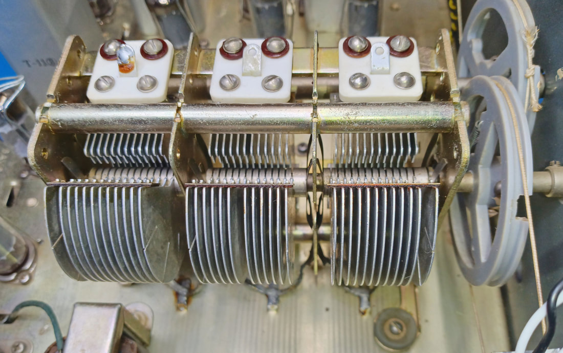
The 3-gang tuning capacitor cleaned up nicely and the bearings were relubed. The tuning mechanism was also relubed and now spins smooth and free. It's weighted tuning is not quite an Eddystone, but you can still spin across the dial in just a couple of flips of the wrist.
|
|
After replacing the six bad oil-filled capacitors and the 10uF cathode bypass electrolytic, the set was powered up on a variac with its original power supply filter caps still installed. All functions were checked and confirmed to be working and even the alignment is very close. At first it appeared the BFO wasn't functioning, but turning down the IF gain showed it was actually oscillating, it's just a bit weak.
|
|
|
Now that I know the radio is functioning I'm going to make a few modifications before going over the alignment. While this set was pretty good for a kit radio, there was still room for improvement in its design. And since it already has a couple of extra holes punched in it, I might as well take advantage of them. For a start there is an article that was written by an amateur radio operator named Bill Orr for 73 magazine back in June 1961, and in it he describes some of his modifications.
The small changes include adding a decoupling resistor and bypass caps to the screen grid of the RF amp, changing a cathode resistor to improve the gain of the 2nd IF amp, adding better filtering to the diode detector audio output and AGC, adding a shield to the mixer tube, and replacing the RF and IF tubes with 6BA6 types.
Some of the changes in the article were actually addressed by Trio (the manufacturer) in their follow on model, the KT-340/HE-30. So I'm actually just going to compare schematics and update the radio as needed.
The biggest mod in the article, and the one most worth implementing, is adding a voltage regulator tube to the B+ line, which will improve the frequency stability of the set. This mod as written requires an extra hole be added in the chassis for the tube, but I want all my mods to be completely reversible, which means no new holes.
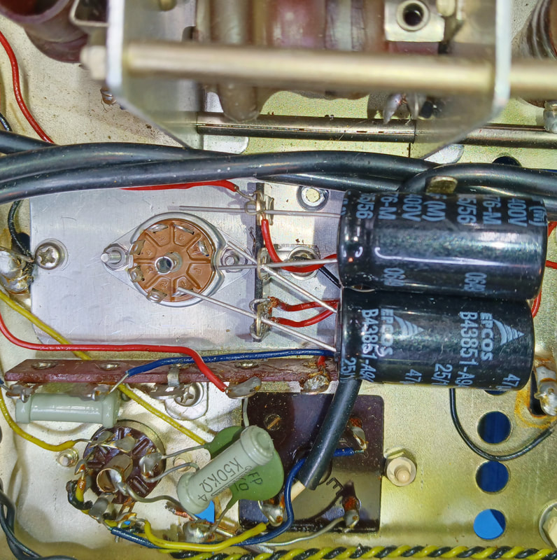
Since I plan to replace the filter capacitors, I decided to remove the old filter can and add the tube socket for the regulator in its place. Normally I would have left the filter can installed for originality, but this time I need its space. The hole is larger than a 7-pin tube socket so I cut a small aluminum adapter plate that attaches to the chassis using the same screws that held the old filter can clamp.
To mount the new filter caps under the chassis, a terminal strip was added at the same time. So far no holes have been drilled, and this mod is completely reversible.
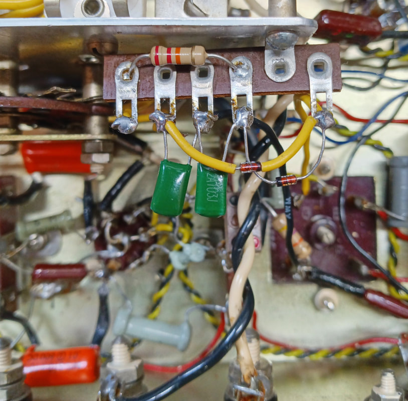
The regulator turned out not to be quite as simple as the article makes out. The 0B2 spec sheet clearly states that any capacitor across the regulator should be limited to 0.1uF or less. Anything larger could cause the regulator to oscillate and destroy itself. But in the magazine article the regulator tube is placed in parallel with a 47uF electrolytic filter capacitor. I tried isolating the tube from the electrolytic by placing a 100Ω resistor between it and the tube anode, however when powering on, the radio's miniature tubes come into emission fairly quickly before the B+ has had time to rise high enough, which pulls the voltage back down, preventing the regulator from striking. I found a fix on the valveradio.net website in an article on optimizing a regulator tube circuit. The solution is to use diodes instead of resistors.
The small changes include adding a decoupling resistor and bypass caps to the screen grid of the RF amp, changing a cathode resistor to improve the gain of the 2nd IF amp, adding better filtering to the diode detector audio output and AGC, adding a shield to the mixer tube, and replacing the RF and IF tubes with 6BA6 types.
Some of the changes in the article were actually addressed by Trio (the manufacturer) in their follow on model, the KT-340/HE-30. So I'm actually just going to compare schematics and update the radio as needed.
The biggest mod in the article, and the one most worth implementing, is adding a voltage regulator tube to the B+ line, which will improve the frequency stability of the set. This mod as written requires an extra hole be added in the chassis for the tube, but I want all my mods to be completely reversible, which means no new holes.
Since I plan to replace the filter capacitors, I decided to remove the old filter can and add the tube socket for the regulator in its place. Normally I would have left the filter can installed for originality, but this time I need its space. The hole is larger than a 7-pin tube socket so I cut a small aluminum adapter plate that attaches to the chassis using the same screws that held the old filter can clamp.
To mount the new filter caps under the chassis, a terminal strip was added at the same time. So far no holes have been drilled, and this mod is completely reversible.
The regulator turned out not to be quite as simple as the article makes out. The 0B2 spec sheet clearly states that any capacitor across the regulator should be limited to 0.1uF or less. Anything larger could cause the regulator to oscillate and destroy itself. But in the magazine article the regulator tube is placed in parallel with a 47uF electrolytic filter capacitor. I tried isolating the tube from the electrolytic by placing a 100Ω resistor between it and the tube anode, however when powering on, the radio's miniature tubes come into emission fairly quickly before the B+ has had time to rise high enough, which pulls the voltage back down, preventing the regulator from striking. I found a fix on the valveradio.net website in an article on optimizing a regulator tube circuit. The solution is to use diodes instead of resistors.
|
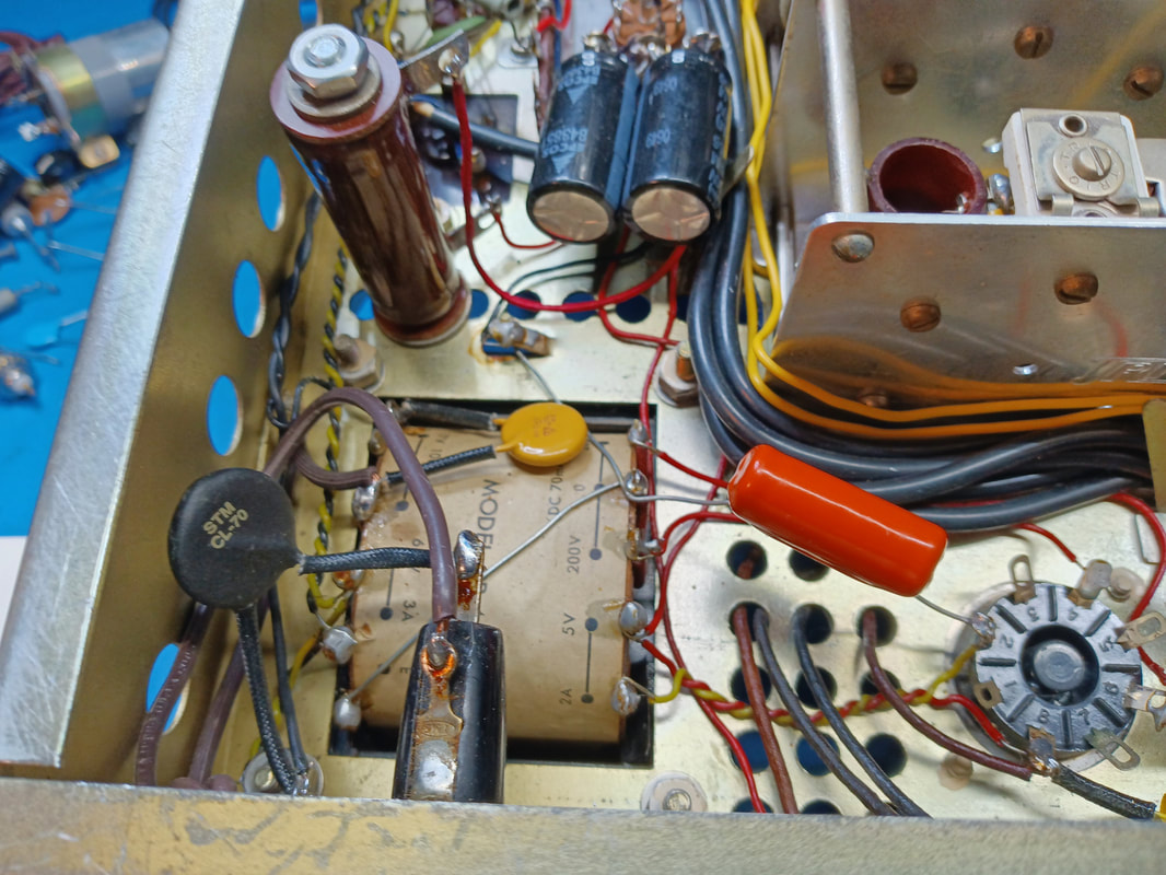
Because of the regulator tube I changed the power supply filter resistor from 2KΩ to 1.5KΩ although the magazine article used 1KΩ, but that was exceeding the 70ma rating of the B+ winding of the transformer and running the regulator tube harder than needed.
To keep everything looking neat I installed a chassis mount Ohmite ceramic brown devil power resistor instead of paralleling resistors as in the article. The regulator is a good idea to help keep the radio from drifting, but the '73 article didn't work as expected. |
|
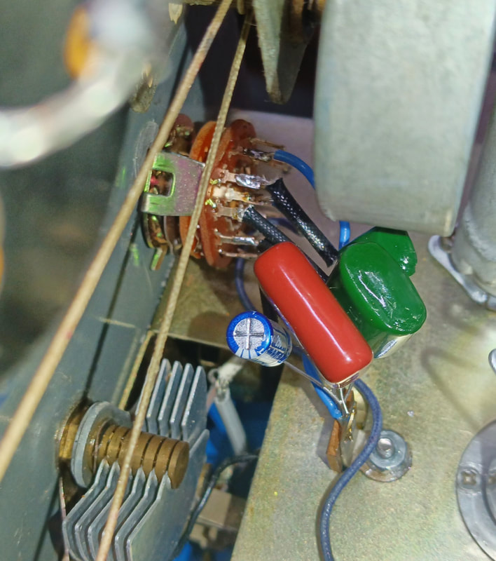
The KT-340 Trio added an antenna trimmer capacitor to the front panel which I tried out on the KT-200 using one of the double holes someone drilled, but I didn't find it very useful, so I reused its panel hole for a switch to change AGC time constants. I filled the top hole of the pair with epoxy and mounted the switch in the lower hole.
|
|
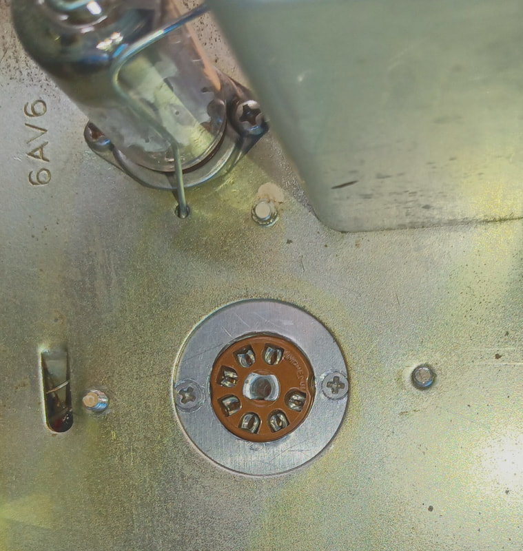
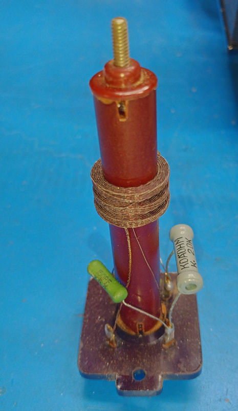
Trio also modified the BFO circuit in the KT-340 to make it a combination BFO and Q-Multiplier. I was thinking of adding it to this radio, and even started rewiring the 6AV6 and BFO transformer, but then changed my mind and decided adding a product detector using the 6AV6's tube socket would be a much better mod.
Inside the coil assembly of the BFO there are two 150pF capacitors and a 20K resistor. For the Q-Multiplier these parts would need to be removed, but now for the product detector they can stay. The tube socket is being rewired to use a 6BE6 as the product detector. The BFO will use grid 1 and the IF input will be on grid 3. The audio output at the plate will be switched to the input of the volume control when the front panel mode switch is set to BFO. The mode switch in the KT-200 has one unused pole which makes it simple to switch between the AM and product detectors. The two detector diodes of the 1st Audio 6AV6 were originally tied together, but will now be used separately. A 1N5711 Schottky diode will be the new AM detector and will use one of the tube diodes for a small forward pre-bias by thermionic electron emission which will make the detector more sensitive to weak signals. The output of the AM detector will also be wired to the mode switch, and will be active in the AVC and MVC positions, but not in the BFO position. |
The second tube diode will now be a dedicated AGC rectifier and the AGC circuit will be modified to add different time constants for AM, CW and SSB.
These detector mods are also adapted from circuits described on the valveradio.net website for the KT-340/HE-30 and the Eddystone 680 models.
These detector mods are also adapted from circuits described on the valveradio.net website for the KT-340/HE-30 and the Eddystone 680 models.
|
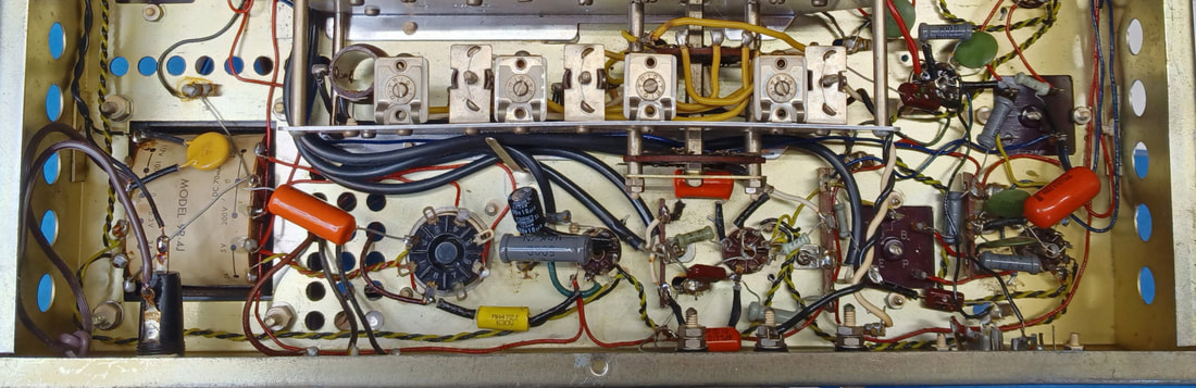
Next is a mod upgrading the ANL from a simple diode audio limiter to an IF noise limiter. It fits on a small terminal strip and is wired across the tapped secondary of the last IF transformer and still uses the ANL ON/OFF switch on the front panel. This noise limiter circuit came from an old 1975 ARRL Handbook.
|
|
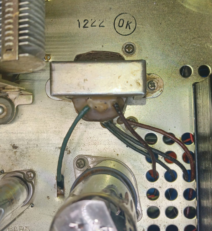
The enameled stranded primary leads of the output transformer have insulated sleeving over them, but the wires are still exposed where they enter the top of the winding, making it a weak point. To protect them I sealed the top of transformer winding with bees wax.
|
|
The dial cover was pulled for cleaning and to repaint the two slightly rusted dial pointers. They're nice and shiny again. The fine tuning pointer was not on zero so that was reset, too.
|
|
Most of the work is finished. A summary of the changes include:
- adding a B+ voltage regulator for the the oscillator, mixer and product detector 6BE6 tubes. - replacing the 2000Ω power resistor in the power supply filter with a 1.5KΩ resistor. |
- replacing the BFO 6AV6 tube with a 6BE6 and rewiring the circuit into a product detector.
- adding separate AM and AGC detectors.
- replacing the 6BD6 IF amplifier tubes with higher gain type 6BA6 tubes.
- replacing the 6BD6 RF amplifier tube with a higher gain 6BA6 tube.
- adding a 1KΩ resistor and a 0.01uF capacitor to decouple the RF amplifier screen grid.
- replacing the 1KΩ cathode resistor in the 2nd IF amp with a 500Ω resistor to increase gain (the Bill Orr mod used a 300Ω resistor, but I found this to be too much gain).
- adding a rotary switch and capacitors to provide a choice of different time constants for the AGC.
- adding a S-9 calibration potentiometer
- adding an external digital display by installing a BNC connector on the rear panel connected via a buffer amp tapped off the cathode of the mixer tube.
- adding CW and SSB audio filters.
- adding a 22pF mica capacitor in series with the BFO pitch trimmer cap to reduce it's range for easier tuning of SSB and CW signals.
- replacing the 10KΩ IF Gain control with a 5KΩ control because it has a bad spot at the top end, and also to spread out its range when reducing the gain.
- adding a polarized power plug and rewiring the AC to place both the fuse and the power switch in the line side.
- adding a surge limiting thermistor to the AC line.
- replacing the 0.01uF capacitor across the power transformer primary with an X1Y2 rated capacitor.
|
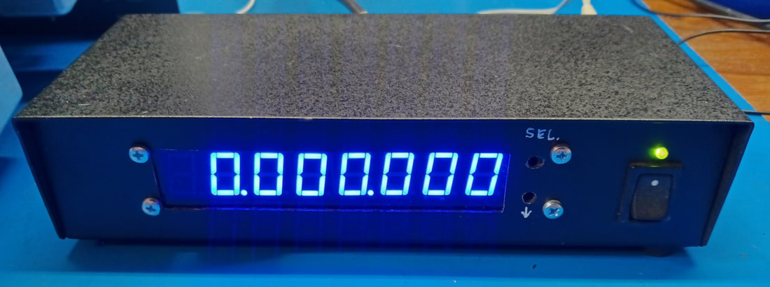
This frequency display is a little project I did a while back and has a programmable IF frequency. The actual frequency counter module inside was purchased online. The counter connects to the BNC installed on the rear panel that taps off the radio's oscillator.
|
|
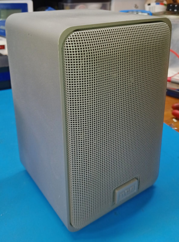
I found an old RCA bookshelf speaker and repainted it gray for use as the radio's external speaker.
|
|
The radio works about as well as it's capable of now. The tuning is pretty narrow and touchy, especially on the highest bands but that's just the nature of it's design. With the product detector, and reduced range of the BFO trimmer, tuning sideband signals is now much simpler. The sensitivity is improved and dial accuracy is good. Plus it now has a digital frequency display.
|
Page created 8/9/2023
Last edited 9/17/2023
Last edited 9/17/2023
