
Restoring an Echophone EC-1
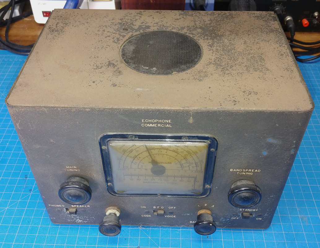
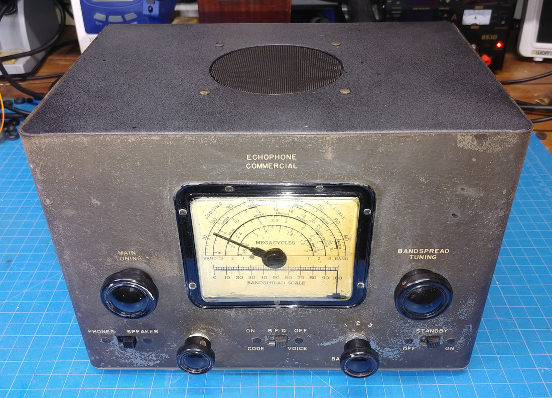
The EC-1 is a simple radio with an interesting history. It was manufactured from late 1940 through 1946 and was advertised and sold by Hallicrafters under the Echophone brand as a morale radio for GI's. It was one of the few commercial radios allowed to be produced during the war and was sold to GI's or their families to be sent as a gift. Hallicrafters would also arrange to ship the radios direct to the GI. Rather clever of Hallicrafters. There is a lot more info online about the EC-1, which I won't repeat here. There was even a cartoon character, nerdy Private Hogarth, seen in advertisements getting all the girls because they want to listen to his EC-1.
This radio is basically a 1940's transformer-less AA5 design with extra band coils to cover the shortwave bands, and an added tube for a BFO.
This radio is basically a 1940's transformer-less AA5 design with extra band coils to cover the shortwave bands, and an added tube for a BFO.
|
The set definitely needs a paint job. I think I purchased a set of decals for relabeling it, but right off hand I can't remember what I did with them. Another little challenge is that the three slide switches are riveted to the front panel, and will need to be unsoldered from the chassis wiring, then taped up while painting. And the dial plastic is also riveted to the front.
|
|
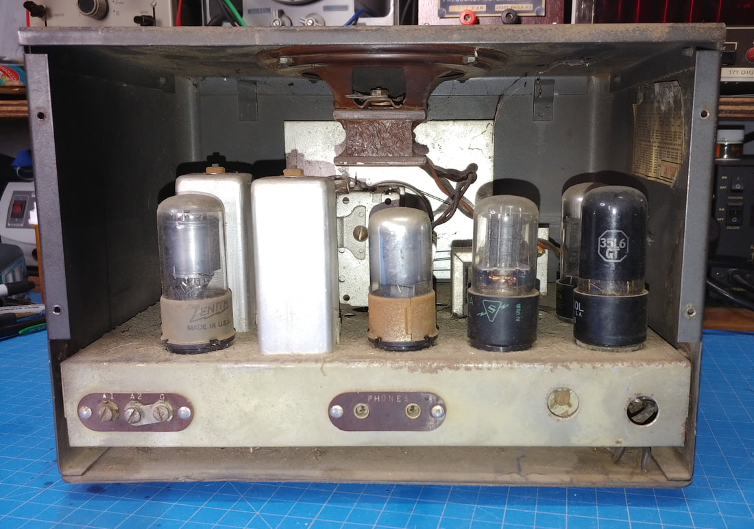
The rear of the set originally had a hardboard back to keep fingers away from the live chassis. To keep the chassis isolated from the metal cabinet, it's mounted on the left and right sides using screws through rubber grommets. But there is one waxed paper capacitor that connected between the chassis and cabinet.
|
|
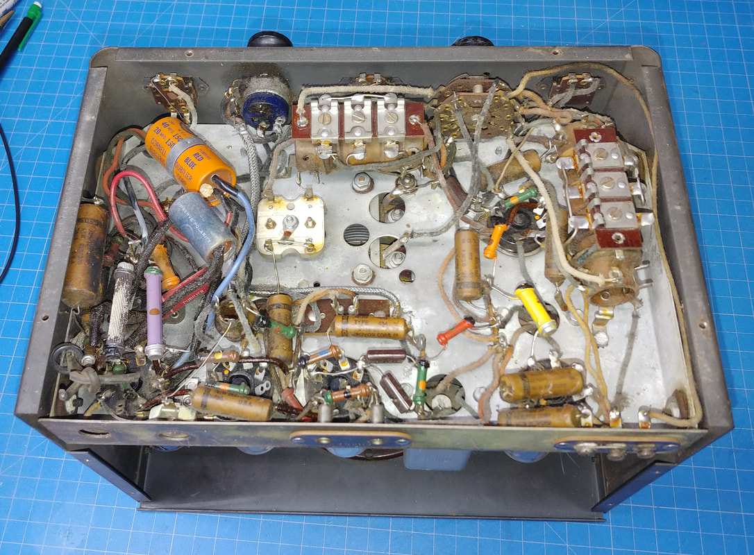
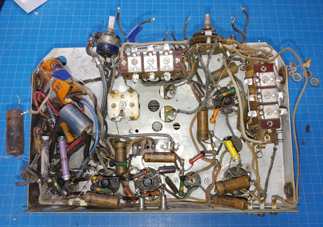
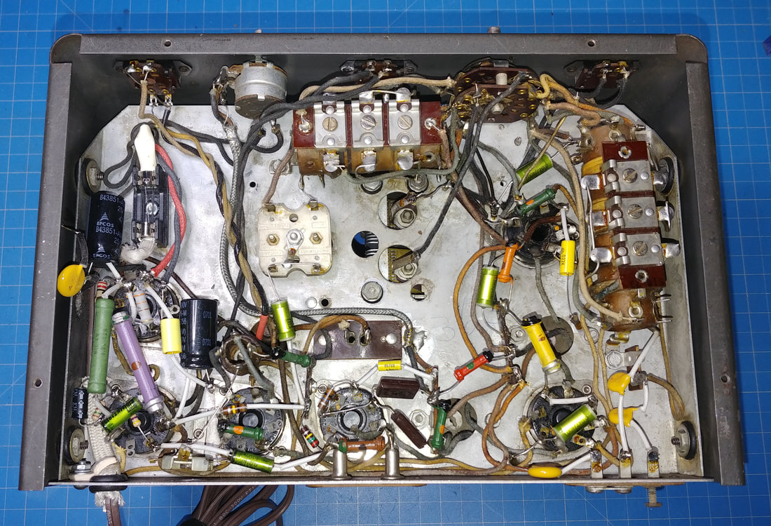
Under the chassis is much cleaner than the top side, but there are visible issues that need addressed around the 35L6 tube. Most of the components are original, but not all.
|
|
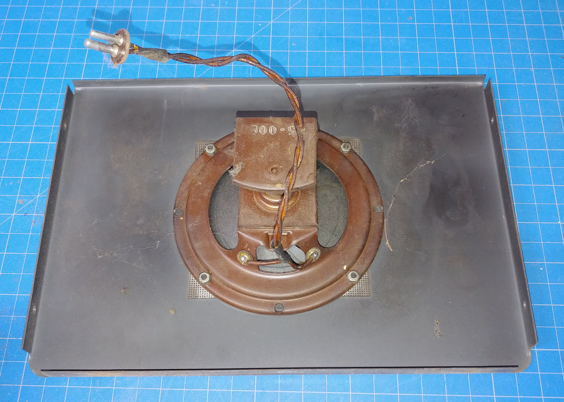
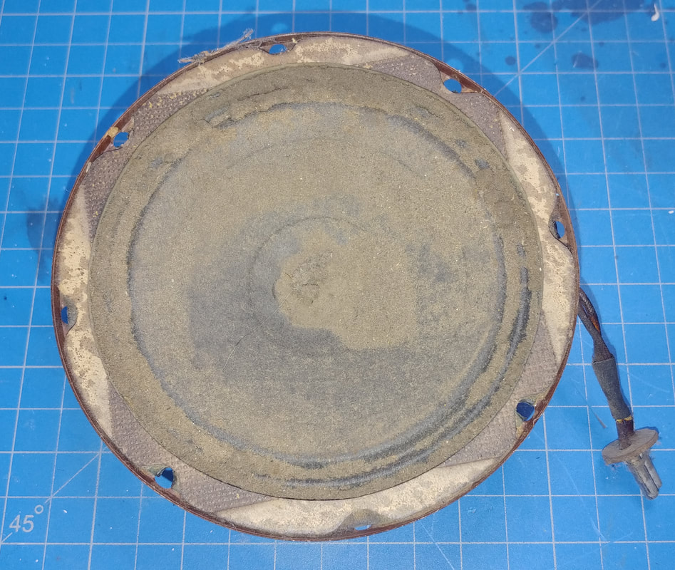
The top panel has the speaker. It comes off by removig four screws and unplugging the speaker.
|
|
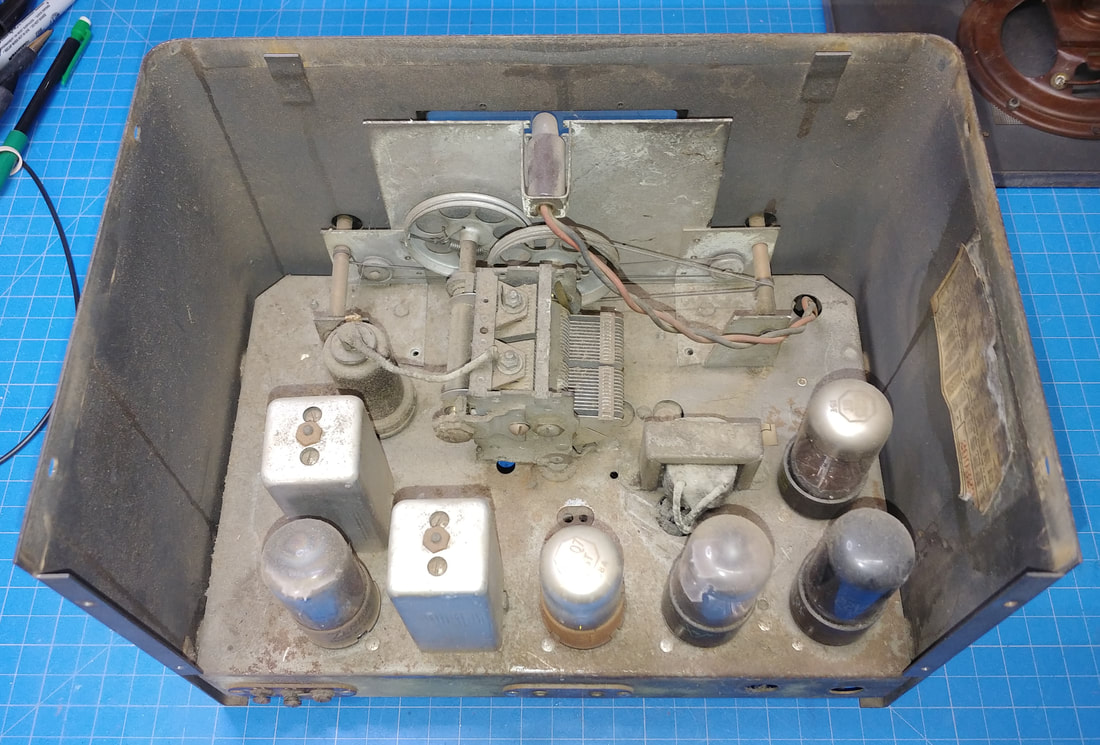
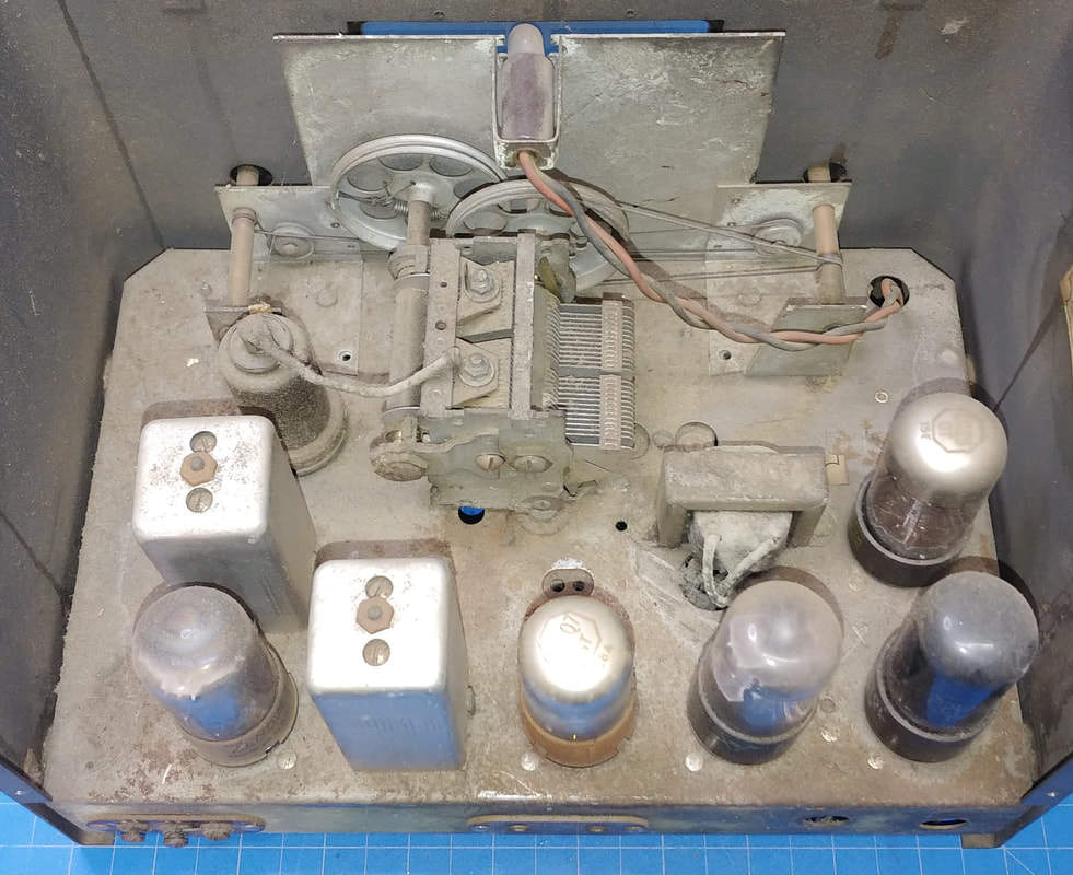
The top of the chassis is buried in dirt and has its fair share of rust too.
|
|
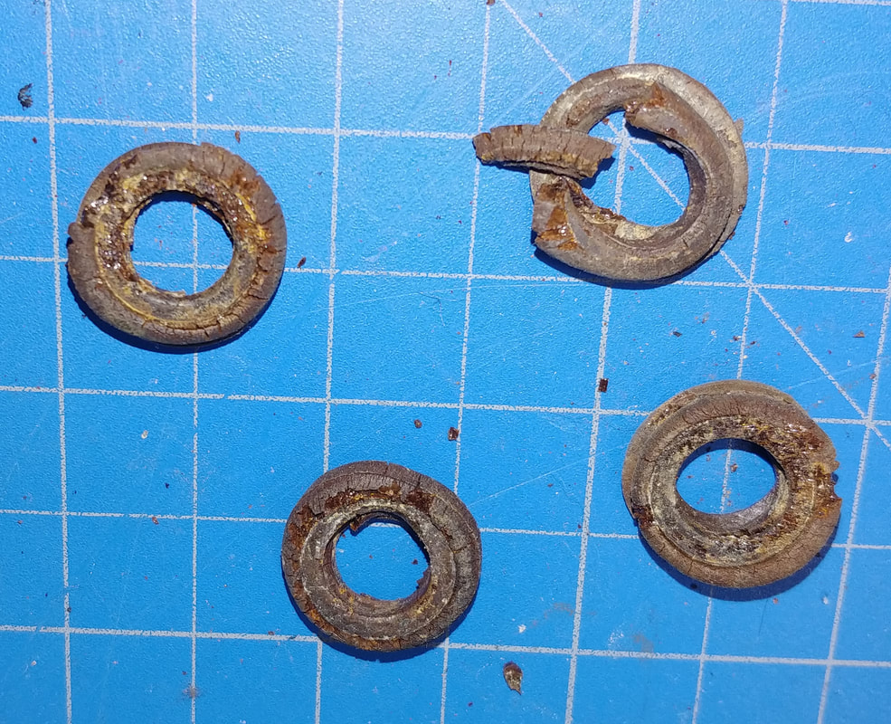
These are the four grommets that are supposed to isolate the chassis from the case. I sliced them off to keep them from crumbling, so I could get a photo.
|
|
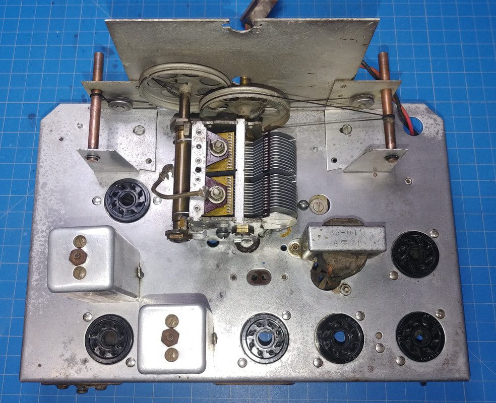
The chassis removed from the case. I unsoldered the front panel slide switches before pulling it out.
I also see there are two gimmick capacitors in this set. A gimmick cap is an insulated wire wrapped a few turns around the insulation of another wire to create a small capacitance between the two. One gimmick is the 10pF capacitor shown on the schematic that injects the BFO signal into the detector circuit. The other is a wire from pin 6 of the 12K8 wrapped around the wire running from the band switch to the right-most pin on the antenna coils visible in the photo. It's not shown on the schematic. |
|
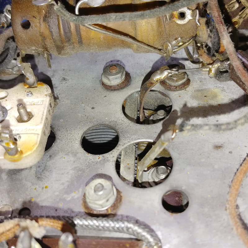
There are three deteriorated grommets on the tuning capacitor mounting studs that also need to be replaced. One thing these grommets do is keep the dial shaft centered in the dial's hole.
|
|
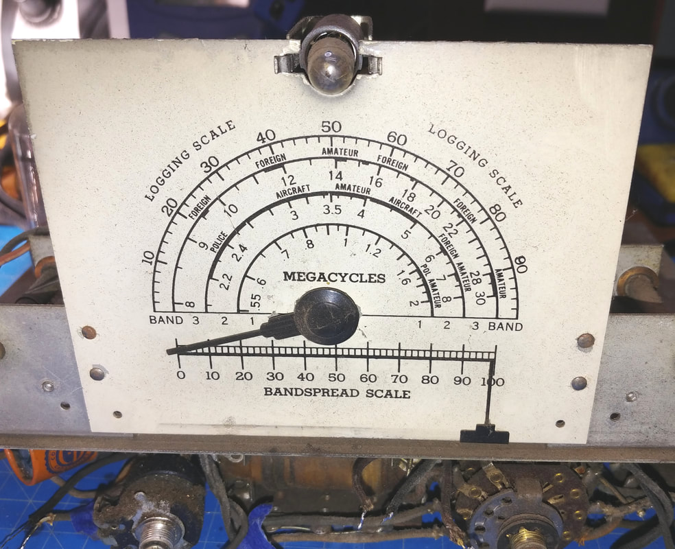
The dial is in pretty good shape, but there a few small spots where paint has flaked off, so I may clear coat the dial to keep any more paint from flaking.
|
|
I think the speaker still has every ounce of dirt that's ever fallen through the speaker grill since the day it left the factory. But under the dirt it's still in good shape and cleaned up nicely.
|
|
|
Before and after of the chassis top. It cleaned up amazingly well. I used several different cleaners and chemicals to get all the crud and rust off.
|
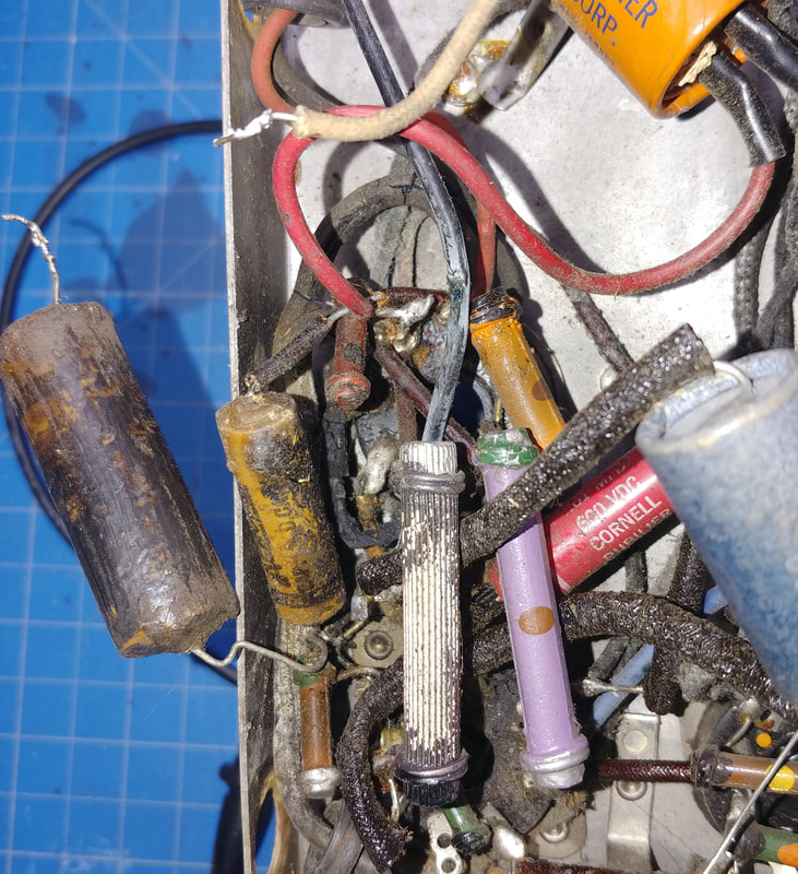
A fire in the making. The power resistor with all the paint flaked off goes from the 35L6 cathode to B+. It got so hot it burned off its paint, burned the sides of two waxed paper capacitors beside it, and if you look closely between the small paper cap and the power resistor, one wire of the power cord snakes down under these components to where it ties to the 35Z5 tube, and its rubber jacket is literally charcoal and falling off. That could have been fun if someone plugged it in, especially since the waxed capacitor tying the case to the chassis was very leaky and could have put the whole case at AC line potential. And needless to say, the 35L6 has seen better days.
I think most of this was caused by someone who attempted to "service" this set a long time ago and did an extremely shoddy job replacing the filter capacitors, the electrolytic across the audio tube's cathode resistor, and one other paper capacitor, also on the audio tube. For example, at the top of the first photo is a red wire from one of the electrolytic filter capacitors which is tack soldered with a glob of solder to a short piece of stranded wire, left when whoever did this cut out the last electrolytic. And it just happens to be right next to the pin where the other AC power cord wire is soldered. It's flying in the breeze and just touching the red wire shorts it to the AC line. |
And if that isn't enough, the old electrolytic's ground wire was also cut off short and left dangling and is shorting the 35L6 cathode to ground. Who knows what else might have been shorted in this whole mess around the 35L6 because yet another glob of solder with the replacement electrolytics ground wires fell off the pin it was supposed to be soldered to. This kind of stuff is why I cut the power cord off sets in unknown condition so they have to be opened up to have a look inside before power can be appplied.
|
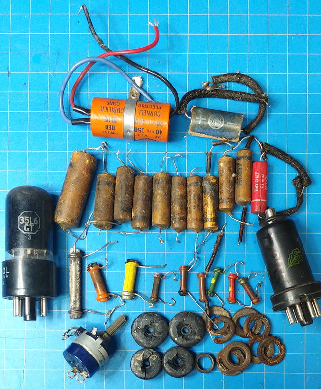
So far I've replaced eleven paper capacitors, the electrolytic cathode bypass cap, the two electrolytic filter capacitors, nine resistors, the power cord, dry-rotted insulated tubing on several components, a weak 35L6 tube and the 12K8 tube, which has an internal short, the four grommets for isolating the chassis from the case and the three grommets for the tuning capacitor. The volume pot had been replaced at some point in the past, but its notched, spline-shaft doesn't allow the knob to line up properly, so it was replaced again with one that does. And four new feet were installed.
|
It's also interesting to note that some of these older style dogbone resistors, like in this set, actually go down in value as they age, unlike "newer" carbon comp resistors that drift high. At least half the resistors replaced in this set were too low in value.
|
|
It's ready to have power applied and see if it works. A polarized line cord was installed and a fuseholder added so the AC line side now goes to the fuse first, then the power switch and finally to the 35Z5. The neutral side goes directly to the chassis. The GND terminal on the rear terminal strip originally went to the chassis through a waxed paper cap, but that's been replaced with an X1Y2 safety capacitor. Safety caps were also added in series with both antenna inputs (as recommended in Mr. Carlson's EC-1 video). And a safety cap connects the chassis to the case, replacing the leaky old paper cap.
Other than cleaning the cabinet, and doing a quick 5-minute paint job on the rusty top and bottom plates, a real wrinkle-finish paint job is going to have to wait for warmer weather. I have to do my painting outside and a wrinkle finish needs warmth to wrinkle properly.
Happily, the EC-1 came up working on its first test. The dial calibration is actually reasonably close on the two lower bands, but the 3rd band was way off. And the IF only needed some minor tweaking. I also adjusted the BFO frequency (trimmer accessed through a hole on the rear of the set) for zero beat. Reception-wise it performs very well, especially considering it doesn't have an RF amp in the front end.
0ne thing I noticed right off is the BFO does not sound good at all, an apparently common issue I had already read about. There's AC hum on the BFO output and it's not strong enough for SSB signals.
From the factory, the BFO signal is taken from the grid of the 12J5 and injected into the 12SQ7 at the detector diode plates using a gimmick capacitor (a wire from the BFO grid that's wrapped around the 12SQ7 diode plate wiring, but not actually connected).
The problem with injecting the BFO signal at the diode plates is a stronger signal is needed to copy SSB. This wasn't a problem back in the '40's as SSB wasn't around then. A second issue is this wire picks up hum which is fed back into the grid of the 12J5 and onto the BFO output, and lastly, tapping off the grid was causing the oscillator frequency to vary. It gave CW signals a bad case of chirp.
So I moved the wire for the gimmick to the plate of the 12J5 to get rid of the hum and chirp, inserted a very small variable capacitor in series with it, and then wrapped a wire attached to this capacitor around the IF transformer lead connected to the grid of the 12SK7 IF amplifier. The small variable cap blocks the DC from the plate of the 12J5, so it's not present at the open end of the gimmick, and reduces the BFO signal so it won't swamp the more sensitive IF tube. Now the BFO works as it should and I can clearly copy SSB stations as well as CW.
Page created 2/5/2021
Last edited 2/25/2021
Last edited 2/25/2021
