Collins 51J4 HF Receiver Rebuild
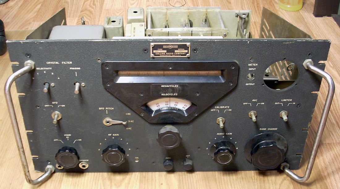
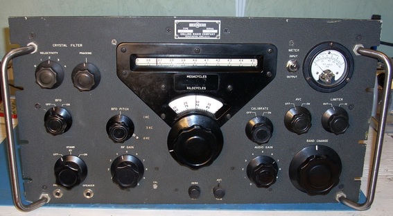
The 51J series of receivers first appeared in 1949 and over the years improvements were incorporated into newer versions. The 51J4 version was manufactured from 1959 to 1964 and was the last and best model produced.
|
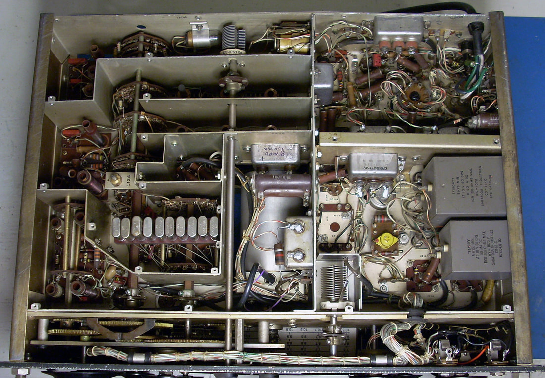
I found this radio at a flea market and picked it up really cheap. It had been cannibalized for parts including all but three knobs, all the tubes and tube shields, the chassis covers, the meter and meter switch, the BFO pitch shaft and coupler, the BFO ON-OFF switch, both phone jacks, the plug-in power supply filter capacitor, all the crystals and mechanical filters, and a couple of tuning slugs. And the front panel Calibrator trimmer capacitor was broken in pieces.
|
I was planning to just use the radio for a parts set but since it is a very collectible Collins receiver I had second thoughts and decided to try to find enough parts to restore it. I had no idea how much work I was getting into...
I dug up all the tubes from my stock and close to half of the tube shields, plus the two phone jacks, a switch for the BFO, several crystals and a couple of the original knobs. Other missing parts, including mechanical filters, crystals, knobs, tuning slugs and capacitors, were found online. I even made a part or two.
|
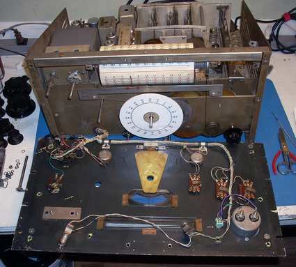
The front panel was pulled to restring the drum, replace the BFO switch, repair the clipped wiring and gain access to the VFO screws for pulling the VFO for repairs.
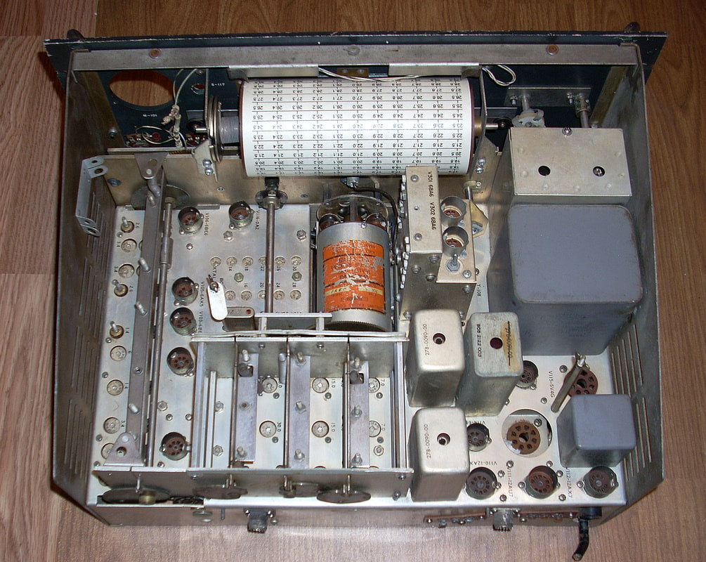
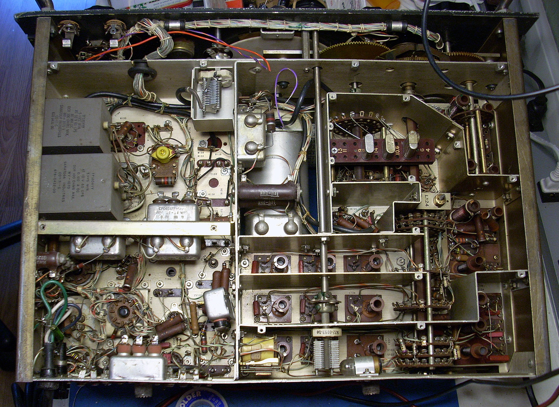
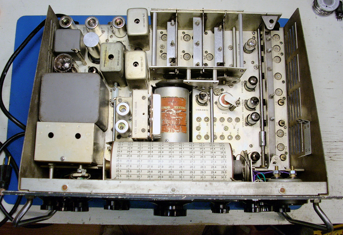
While the chassis was on the bench I also checked all the resistors and replaced several that were out of spec. And I cleaned and lubed all the mechanical linkages because I was having issues with the slug racks sticking and cocking to one side, which actually cracked a couple of slugs. Fortunately these were easily repaired with JB Quick Weld epoxy. Finally, I also replaced some MicaMold 100pf capacitors that are notorious for failing. One in the AVC circuit was bad and the others were changed as a precaution. |
|
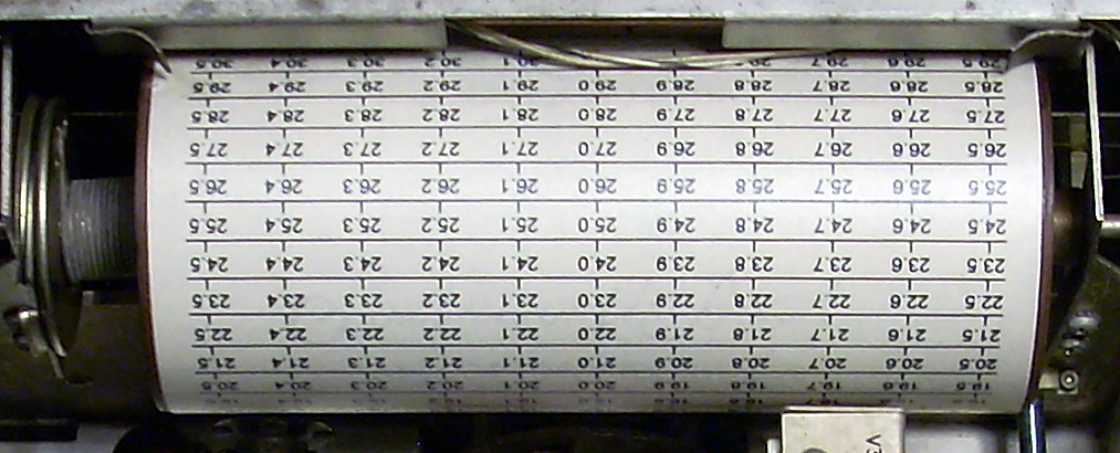
The Megacycle drum dial was nearly illegible from age and abuse so I printed a new dial from a PDF file found on a Collins restoration site. I sprayed the dial sheet with several coats of clear acrylic spray to give it a protective waterproof surface.
The cord from the drum down to the band switch mechanism was also missing and was replaced. |
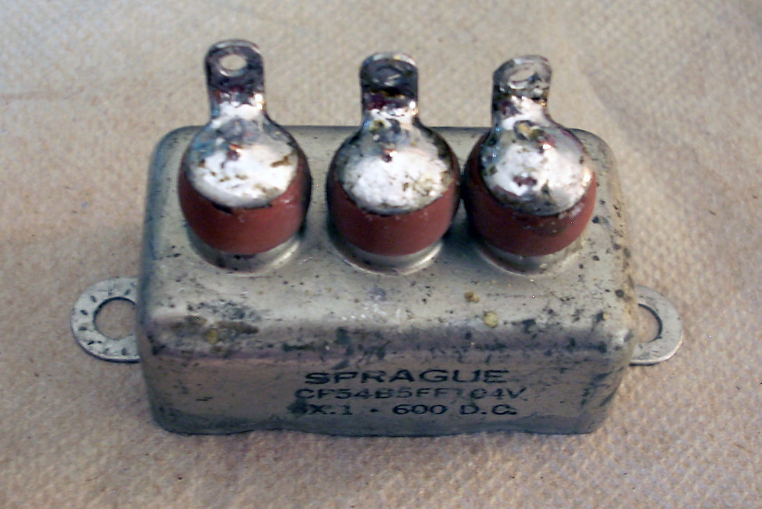
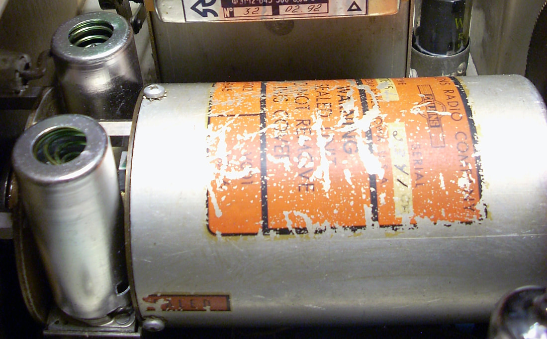
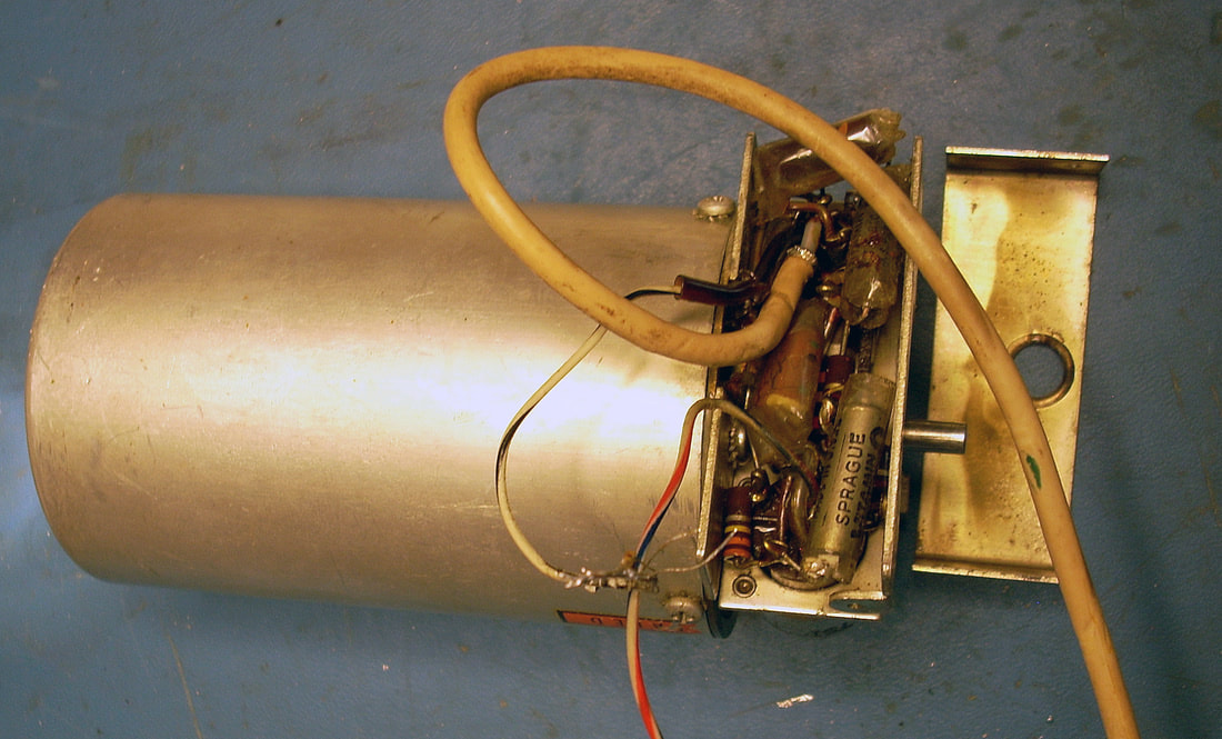
I rebuilt the "bathtubs" containing the larger capacitors. The backs were cut open, the old contents extracted and new parts soldered in. One bathtub had a terminal with a high-ohms "short" to the case and was replaced with a rebuilt old stock bathtub that I had on hand.
FYI: I don't recommend cutting open oil-filled bathtub capacitors. The oil might contain PCBs and should NOT be messed with. Not all bathtubs are oil-filled, for example electrolytics I've opened aren't, but I no longer take any chances if I'm not sure. I just trash them. Better safe than sorry.
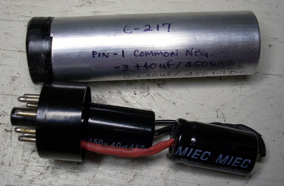
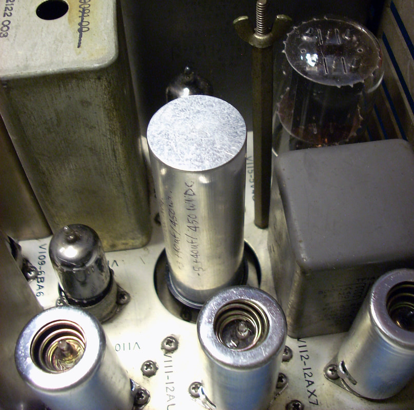
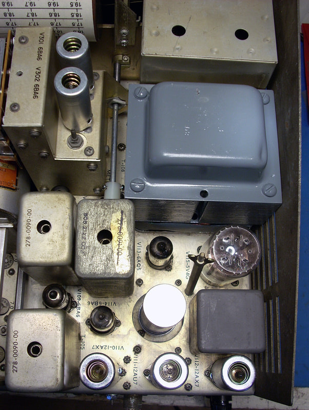
The power supply filter capacitor was made from an octal tube base, an aluminum can that originally contained medicine, and two 40-uF electrolytic capacitors. I used spray-on stripper to remove a painted label from the can and it just slips down over the capacitors and into the tube base. I taped the end of the can so it couldn't short to a socket pin.
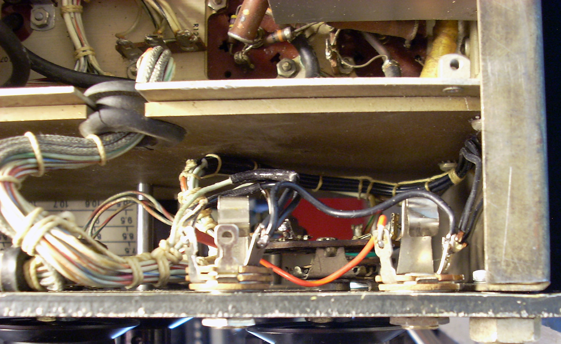
When the meter, meter switch, BFO switch and phone jacks were removed someone did it by cutting the wires off close to the harness, so new wires were spliced in to reattach these components.
|
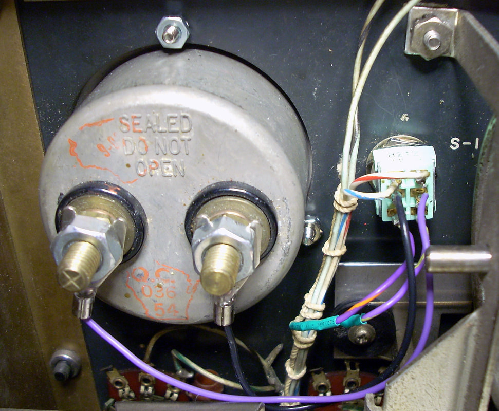
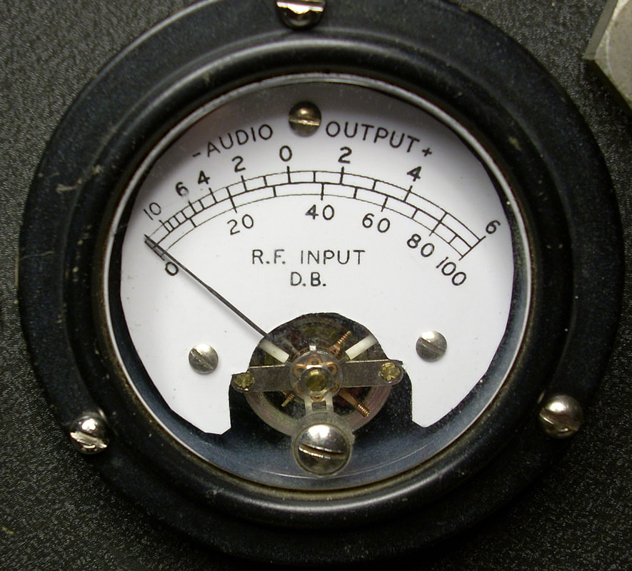
I couldn't find an original meter but discovered by chance that a meter from a URM-25 signal generator is a perfect match in size and hole pattern. So I ordered a used URM-25 meter from Fair Radio Sales for 10 bucks. The new meter has a 100-ua movement (the original was 1-ma) so a shunt resistor was added internally to get a full scale reading at 1ma.
A new meter face plate dial was created in Photoshop from a 51J4 photo I found online. This meter will have to do until I come across an original one. |
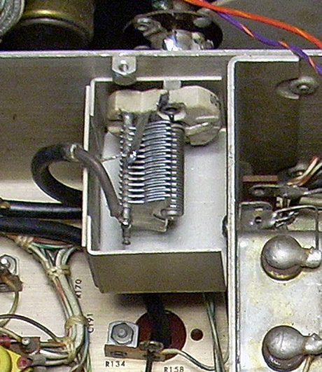
I found a replacement for the busted crystal calibrator trimmer capacitor in a box of parts picked up at a hamfest.
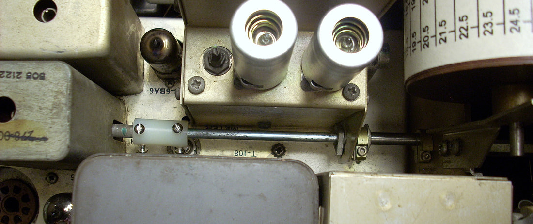
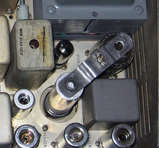
For the missing BFO parts I made a replacement shaft coupler from a nylon spacer and the BFO Pitch control shaft from a 3/16 rod. A piece of brass tubing 3/16" inner diameter and 1/4" outer diameter was slipped over the end of the pitch shaft so the knob would fit proper.
For the missing BFO parts I made a replacement shaft coupler from a nylon spacer and the BFO Pitch control shaft from a 3/16 rod. A piece of brass tubing 3/16" inner diameter and 1/4" outer diameter was slipped over the end of the pitch shaft so the knob would fit proper.
|
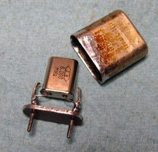
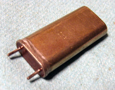
Locating some crystals wasn't too difficult - I found someone selling sets of R390 crystals which had several of the crystals I needed. And I found the 10.6Mhz crystal from a seller in Serbia. I had a 4, 6 and 8 Mhz crystal in my junk box, but they turned out to be out of spec, and I couldn't find reasonably priced replacements in the HC-6/U style case. However, I did find all three frequencies in the smaller HC-18/U cases really cheap. So I took some useless HC-6 crystals, unsoldered them and then soldered the HC-18 crystals inside in place of the original crystal. I soldered the cases back together so they look original and they work fine. Again, they'll have to do until I come across affordable originals. I spent about 5 or 6 dollars each on 5-packs of HC18/U crystals, so that saved me at least 40 bucks over the price of the few original crystals listed online, and even left me with a pile of extra crystals.
|
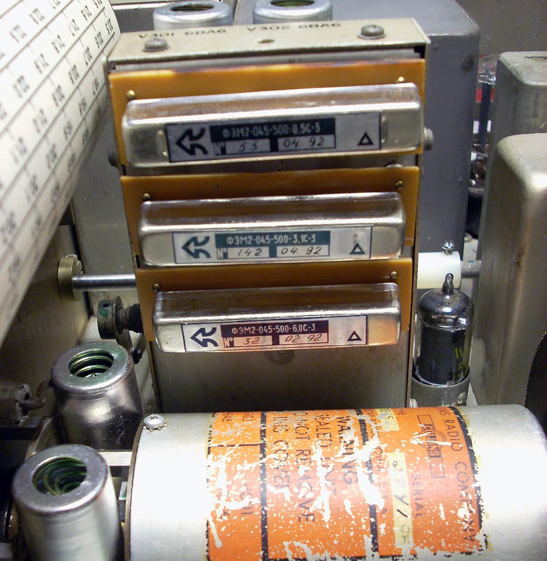
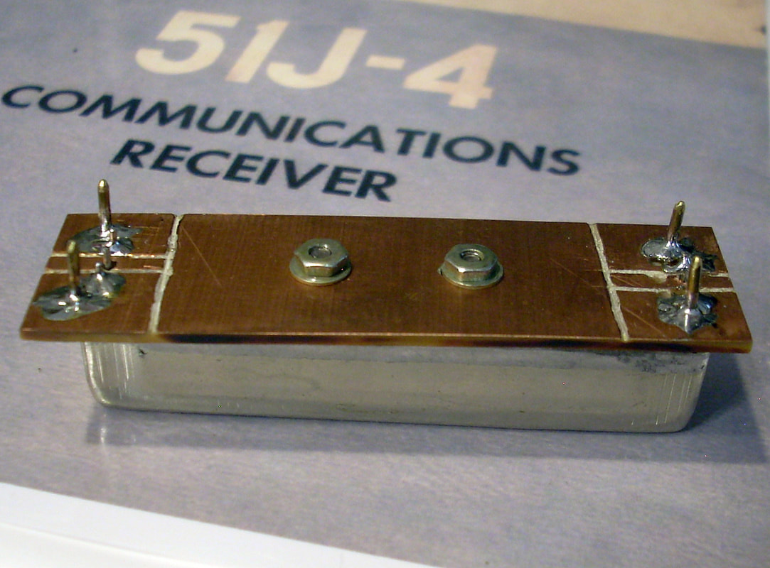
The most expensive replacement parts for the set are the three Collins mechanical filters, if you can even find any original filters, which I couldn't. But I did manage to locate online a complete set of Russian 500KHz IF mechanical filters, with bandwidths of 0.5KC, 3.1KC, and 6KC, from a seller in Ukraine at a very reasonable cost. They need a simple adapter board (google VE7CA's 51J4 web page) to plug into the 51J4, but at least I found a set of filters and they work.
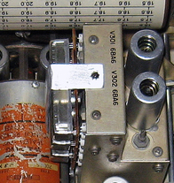
The VFO was loose so I removed the front panel and pulled it to see if anyone had tinkered with it. While it was out I replaced the capacitors under the two 6BA6 tubes and checked the tolerance on the resistors and replaced a couple of those too. I also replaced the old stiff-as-a-board coax cable. I did not try to trim the coils to tweak the band ends. I'll have to check the set first to see just how far off the ends are.
|
Most of the missing parts have now been replaced, but still waiting on tube shields from China.
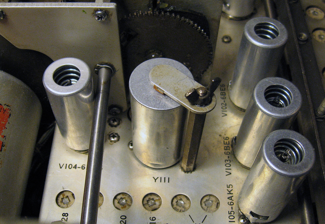
I located all the tube shields at reasonable prices except for the two tall 7-pin tubes in the radio. I'll look for them at local hamfests. Neither is really necessary but I'll still install them when I find 'em for the right price (cheap). There is still a lot of testing and aligning to do on the set before the job is complete. |
So far in my quest for parts I've purchased mechanical filters from Ukraine, a crystal and tuning slugs from Serbia, tube shields from China and replacement capacitors from Canada. This radio is turning into an international project.
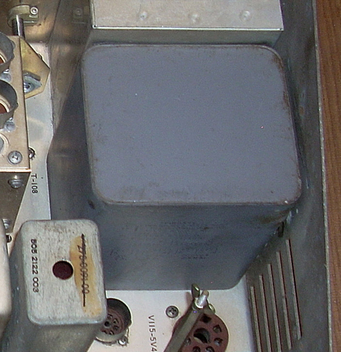
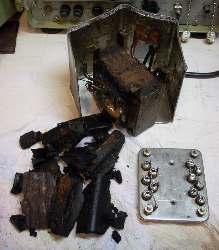
This radio is starting to try my patience. Now that I have it to a point that it can be powered up, I discovered the B+ voltage is low and traced it back to the high voltage winding of the transformer. One side of the 700-volt center-tapped winding is open. I cut open the transformer and dug out all the potting compound to see if it was repairable. It wasn't so I pulled the bottom plate to reuse in mounting a replacement.
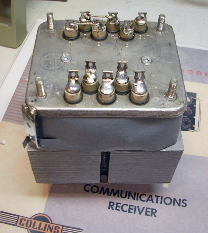
A little online searching turned up a replacement transformer with similar electrical specs, and that just fits in the footprint of the old transformer, for just 17 bucks plus shipping.
Attaching the bottom plate to the new xformer lets it install just like the original with no mods to the radio or wiring. I got off pretty easy on this one.
I'm betting the bad power transformer was the reason someone originally used this radio as a parts set instead of restoring it.
Attaching the bottom plate to the new xformer lets it install just like the original with no mods to the radio or wiring. I got off pretty easy on this one.
I'm betting the bad power transformer was the reason someone originally used this radio as a parts set instead of restoring it.
After replacing the power transformer I tried aligning the radio but ran into problems with the calibrator. The calibration points were off. The original Collins 100KC crystal was missing when I bought the set and I had substituted another crystal. So I substituted a second 100KC crystal but got the same result. I was really scratching my head for a while until I finally tried a third crystal and problem solved - the first two crystals had drifted from age.
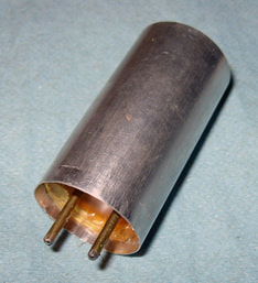
Only problem now is the good crystal has smaller pins and won't plug into the crystal socket. To mount the crystal I made a can with a proper base using another medicine container like the one for the filter caps, except cut shorter.
Only problem now is the good crystal has smaller pins and won't plug into the crystal socket. To mount the crystal I made a can with a proper base using another medicine container like the one for the filter caps, except cut shorter.
The base is phenolic pcb and the pins are brass tubing. The crystal plugs into the brass tubing inside the can and is sealed shut with hot glue. It also looks more like an original crystal when installed.
Other issues needing attention included a dead Band 1. The cores for the Band 1 coils were missing and I installed replacements, but the tuning was so far out I could not receive any signals. After much fussing with the alignment I finally got the tuning slugs readjusted and brought the band back to life. I also installed a Dallas Lankford mod, from Hollow State Newsletter #26, by adding a 10pf capacitor in parallel with C117 to improve sensitivity.
Another issue was misalignment on Band 4: signals were about 25KHz high. That turned out to be the 6MHz crystal being out of tolerance. As mentioned previously, I could not find a reasonably priced replacement so I "made" a crystal by installing a 6MHz HC-18 crystal into an HC-6 case.
Finally, I am at the point of having the radio back in working condition with all controls functioning, reasonably well aligned, and receiving on all bands.
Product Detector and AVC Mods
|
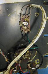
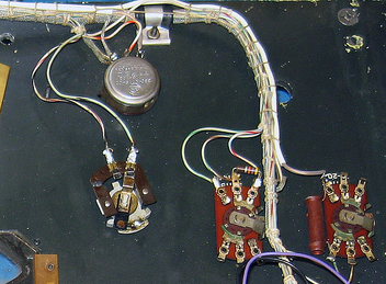
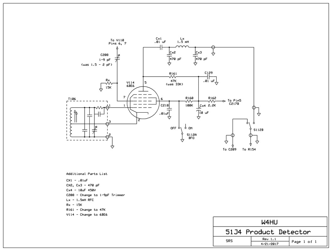
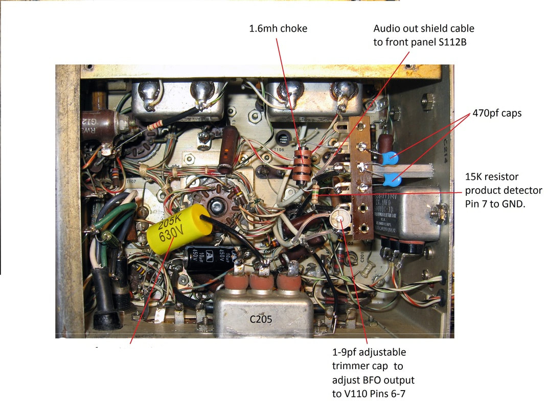
Now that the radio is working I'm adding a product detector and modifying the AVC circuit. These seem to be the two most recommended improvements for the 51J4. For the product detector mod I am using the mod by Dallas Lankford which was published in the Hollow State Newsletter #28. I had to pull the front panel (yet again) to wire the unused section of the BFO switch, and change wiring between the Noise Limiter switch and audio pot. On the right, three shielded cables for the product detector mod have been added and laced in.
I also took the opportunity while the front panel was off to install a more original looking meter switch than the first one I used. |
The original BFO switch was DPDT. It was missing from this radio and I replaced it with just a SPST wafer switch since only two contacts are used to switch a ground. However, the product detector mod requires a DPDT switch so I swapped the SPST with the DPDT switch from the Calibrator since it too only uses two contacts to switch a ground. I'm glad Collins used the same switch everywhere regardless of how many contacts were actually needed.
|
I changed the pi-filter output choke and capacitor values to use components I had on hand and they seem to work fine. I also added a variable capacitor for tweaking the BFO output level as Lankford recommended in a later update article from newsletter #36.
The BFO output resistor on V110 pin 7 was changed to 15K as done by another ham (W8UT) in a schematic of his version of the mod that I found online. |
The AVC circuit has to be modded for the Product Detector to work well. My mod is based on Lankford's AVC mod, in his newsletter #26, but it is a bit simpler with only 3 additional parts plus some different component values. Some of the component values were again taken from the W8UT version of the mod.
The audio amp in the 51J4 is said to be nothing to brag about, but the product detector and AVC mods deliver much better sounding SSB and CW audio than I was getting from the diode detector. Now the diode detector is strictly for AM use.
The audio amp in the 51J4 is said to be nothing to brag about, but the product detector and AVC mods deliver much better sounding SSB and CW audio than I was getting from the diode detector. Now the diode detector is strictly for AM use.
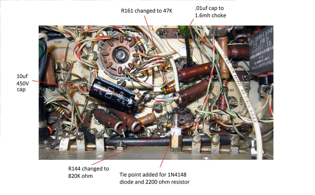
I am really pleased with how the radio sounds with these modifications. My adaption of the mods was aimed at keeping the radio as close to original as possible and making the mods completely reversible; no wiring cut off, no irreplaceable parts removed and no extra holes. I changed the tube to a 6BE6, moved a couple of wires on the BFO tube socket, changed a resistor value and added a few parts, but all done so the radio can be restored to original if desired. That being said, I don't plan to remove the mods as they really do improve SSB and CW reception. There's an issue I've noticed where switching to AGC pegs the meter momentarily and I'll need to correct that when I have time.
The first photo has C205 removed to see components under it. The second photo is the completed modification.
The terminal strip is mounted on a standoff and the parts layout on the strip was so I could experiment with different component values, but in the end I didn't need to change anything. It worked right out of the box.
The terminal strip is mounted on a standoff and the parts layout on the strip was so I could experiment with different component values, but in the end I didn't need to change anything. It worked right out of the box.
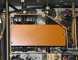
I made replacements for the strap securing the mechanical filters, the plate holding the filter capacitor and rectifier tube in place, and the phenolic plate over the crystals. I still need replacement top and bottom covers and a cabinet to finish off the set.
After one final alignment the radio is working pretty well. I was originally planning to repair it and sell it but it is such a nice set I've had second thoughts and think I'll just keep it for the shack.
Revisiting the Collins 51J4 Receiver
After spending several months working on the 51J4 I finally had to call it quits because there were other projects waiting. But there's still things I'm not completely happy with that I want to revisit, and since I last worked on it I've picked up a full set of original crystals, an original meter and a cabinet, and found some other odds and ends that will make for a more authentic rebuild. I even picked up another VFO in case I should need it. So when I find the time I'm going to put it back on the bench and go over it all again.
The first go around focused on just saving it and getting it in working condition again. The next round will be getting it back as close to original as I can.
The first go around focused on just saving it and getting it in working condition again. The next round will be getting it back as close to original as I can.
Page created 10/2017
Last update 12/23/2021
Last update 12/23/2021

