
Starshoot Pro CCD Camera V1 Noise Reduction Mods
On the old Starshoot Pro Yahoo group one of the group's members posted information on his efforts to reduce electronic noise in the SSPRO version 2 camera. The version 1 camera is very similar so I decided to try his mods to see if a reduction in noise would be noticeable. I also replaced the fan with a lower noise/lower vibration unit from Digikey that was also recommended on the group.
I also used the procedure detailed on the old group to set the camera's gain and offset, as the Orion defaults did not maximize the camera's gain. Download speed also affects the offset value so the gain and offset should be adjusted for a specific speed. Another apparent characteristic of the camera discussed on the group is that short exposures of less than 1 minute exhibit more background noise than longer exposures, so the offset should be adjusted using a minimum 1 minute exposure.
One of the camera's shortcomings is the "dreaded 9-pixel dashes" data loss that occurs if the subs are downloaded at too high a speed. Although the camera is a USB 2.0 device this was basically cured by connecting the camera to a USB 3.0 port on my workstation.
The standard disclaimer applies: Open your camera at your own risk. This is delicate (and expensive) static-sensitive electronics and can be easily damaged if proper precautions are not taken.
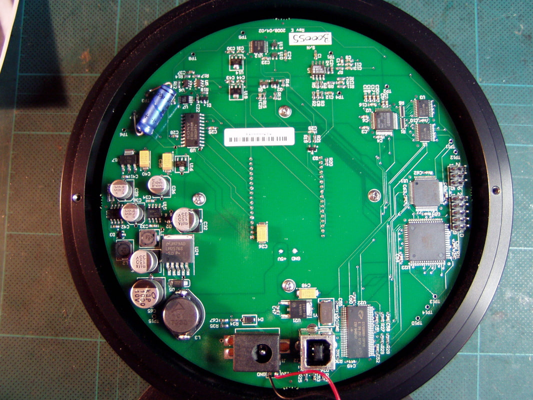
SSPRO V1 PCB Before Modification
|
The unmodified PCB. The fan wiring originally lay across the center right of the board. At first I rerouted the wires along the right edge of the case with no apparent issues. Then, when I did the set point cooling mod I rerouted the wiring under the PCB on the right side.
|
|
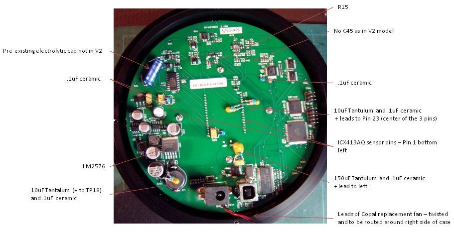
The following capacitors were added to the PCB:
|
Measuring Camera Parameters
I used Craig Stark's article "Signal to Noise: Understanding it, Measuring it, and Improving it, Part 3 - Measuring your Camera" to perform the measurements, as well as the "Understanding CCD Read Noise" article on the QSI website to create Fast Fourier Transform (FFT) images of readout noise using ImageJ.
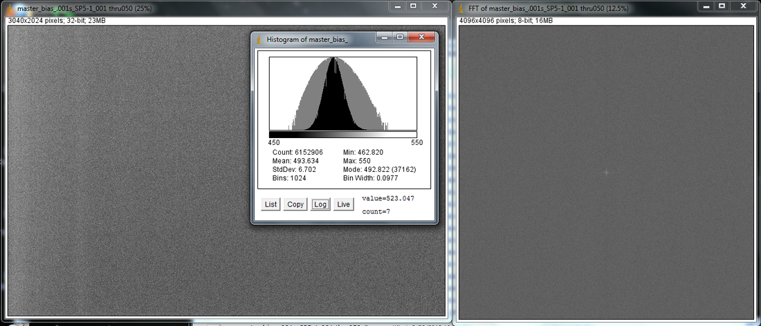
The FFT gives a quick visual check of read noise: an FFT with no noise would have only a central dot. Vertical lines show horizontal noise and horizontal lines indicate vertical noise. The QSI page has a primer on interpreting FFT images that explains them better than I can.
The results from my Starshoot Pro look good for a camera in this price range. Now that I have the gain, offset and speed optimized, and with the set point temperature modification (and the APS-size sensor), my Starshoot Pro has found new life just when I was about to retire it for an SBIG ST-8300C. I eventually sold the ST-8300C and kept the SSPro as my primary imaging camera because of it's larger CCD.
Before Modification Image
|
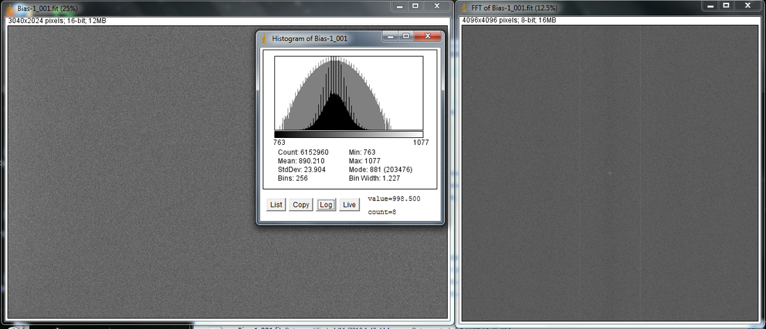
This is a single bias frame from before the noise mod. Unfortunately I forgot to record the download speed, but it was likely at speed 2. Notice the two vertical lines in the FFT indicating some horizontal spatial noise is present. Comparing this FFT to the after-modification FFTs below shows that this noise was reduced.
You may notice the readout noise is actually less - 24 ADU - than in the bias frames below from after the mod, but this frame was taken when the gain was still set at the factory setting of 50% (32K ADU) so it is not a direct apples-to-apples comparison - more gain equals more noise. I would need to reset my camera back to 50% gain to capture a comparable frame, which I am reluctant to do now that I have the camera optimally configured. |
After Modification Bias Frames and FFT Images
|
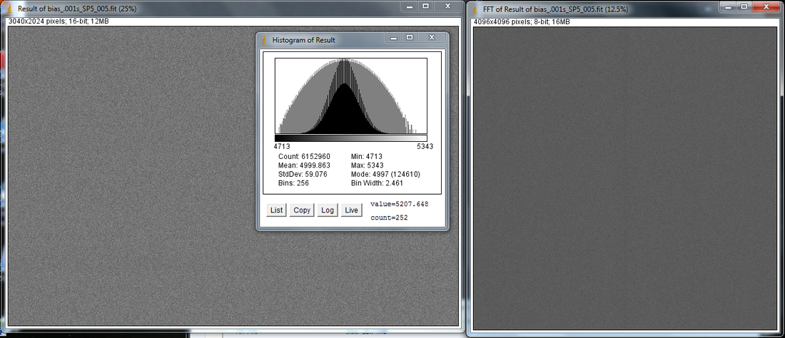
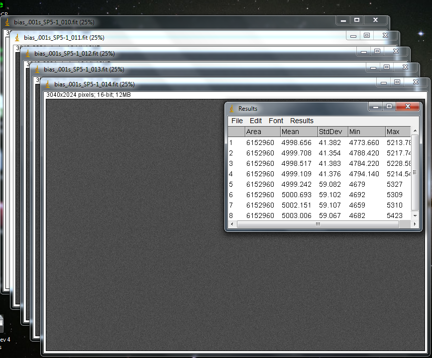
The CCD temperature was set to -5° C and frames were downloaded at speed 5 (the fastest setting without download artifacts as explained below).
At left is a read noise result from subtracting two bias frames. The FFT is on the right. The histogram has a just a little tail on the right and the FFT is free of strong spatial frequencies. |
|
This is a master bias frame made by averaging together 50 individual bias frames along with the histogram and FFT. Not a perfect bell curve as it tails off to the right.
|
|
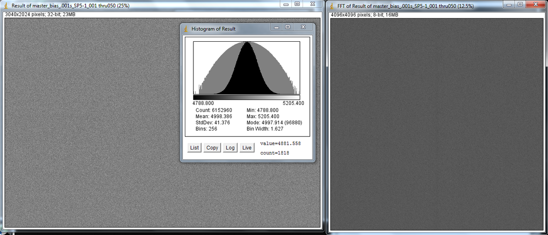
This is the result of subtracting an individual bias frame from the master bias. The histogram shape looks more symmetrical.
|
Image Download Artifacts
|
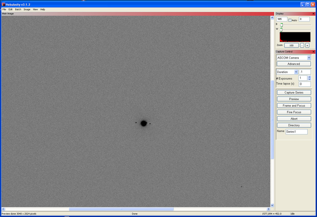
This is an inverted image screenshot of Jupiter at download speed 5 for reference. No download artifacts are visible.
|
|
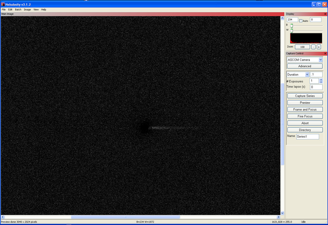
At the fastest download speeds (6 - 8) bright objects have a black streak extending to the right. This is an inverted high-contrast screenshot of Jupiter emphasizing the download artifact.
|
|
Here is a test shot of the Orion nebula downloaded at speed 8. If you look close you can see the black streaks to the right of bright stars in the image. So, even though the new USB 3.0 card in my workstation allows me to download at speed 8 without 9-pixel dashes, I still get other undesirable artifacts.
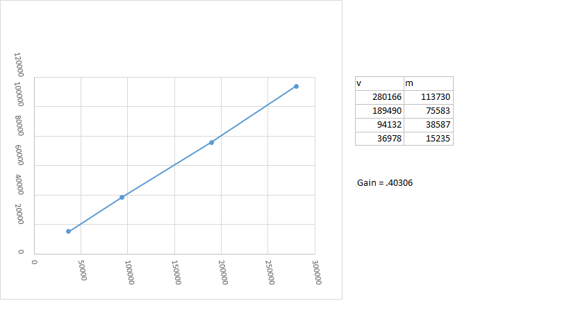
Speed 5 was as high as I could manage (using the USB 3.0 port) without these streaks appearing in images. As a result I set my cameras speed to 5 and adjusted the gain and offset for that speed. This is still a good improvement over the speed 2 that I was limited to with the USB 2.0 port. Using Maxim DL Essentials I adjusted the gain to give 65535 levels and the offset to a mean value of 567. The new settings applied in Maxim DLE (using the Gain and Offset controls download from the Starshoot Pro Yahoo group) are: - Gain = 50 (50 is the setting for 100% gain, not the actual gain which is calculated below) - Offset = 460 (the mean of the actual resulting offset is 567) - Substrate = 250 (default setting) |
Gain and Readout Noise Calculations
|
After setting the camera parameters, and capturing and analyzing the bias, flat and dark frames, the camera parameters were calculated as follows:
|
|
Final Results:
|
