
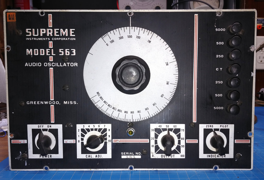
Restoring A Supreme Model 563 Audio Generator
The model 563 dates back to at least 1941. it's in Supreme's 1941 catalog, and the 1945 Supreme schematic I found says it supercedes the 1941 version. But the design goes further back to 1939 and the Model 561 AF/RF Combination generator.
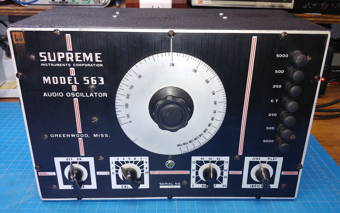
This 563 is serial number 161 and has an orange ink stamp (SC 225 A) in the upper left corner, like stamps I've seen on some WWII military gear, so looks like this one was made for the military.
According to the 1945 war time catalog it was possible for a service shop to order one of these, but there was a three month wait involved, and its advertised price was $56.15.
|
This model is basically a standalone version of the audio generator in the Model 561 generator, which is a Beat Frequency Oscillator (BFO) audio generator. This means it doesn't actually oscillate at audio frequencies. Instead it beats two higher frequencies together (200KC range) to produce a sine wave audio tone.
This 563 is advertised to generate audio from 15 CPS to 15 KC, but it actually goes down to 0 CPS (zero beat) and tops out at about 18KC, although there are no dial marks above 15KC. It can also output a fairly strong signal, as high as 65-volts RMS unloaded. |
And it has a nice output transformer that can supply a balanced output for push-pull inputs, or unbalanced for single-ended, at 250, 500 and 5000 ohms impedance. Although the generator's circuitry is nearly identical to the model 561 generator, the 561's output impedances are a bit different - 50, 500, 5000 and 50000 ohms. Turning up the signal on the 563 with nothing connected to the output causes the output transformer to "sing", so it's probably a good idea to keep the output low with no load.
The front panel controls include a calibration adjustment, output level control, and a neon pilot lamp that can be switched to act as a zero beat indicator when calibrating. This is another difference with the model 561, where a meter is used for zero beating the two oscillators.
The front panel controls include a calibration adjustment, output level control, and a neon pilot lamp that can be switched to act as a zero beat indicator when calibrating. This is another difference with the model 561, where a meter is used for zero beating the two oscillators.
|
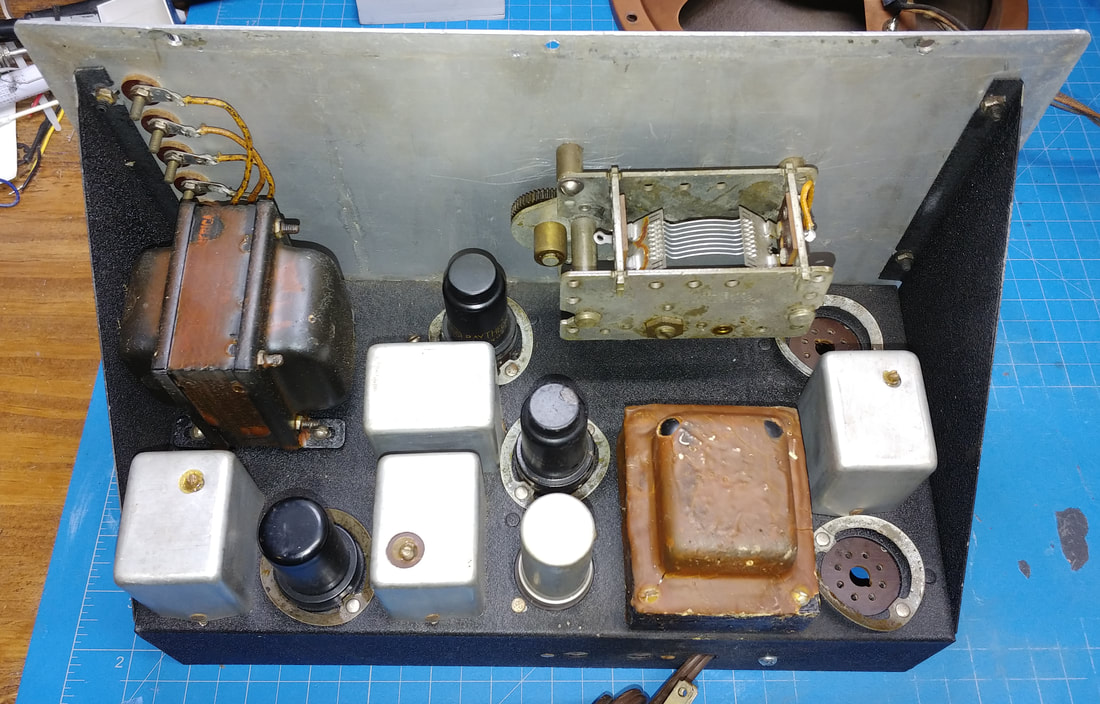
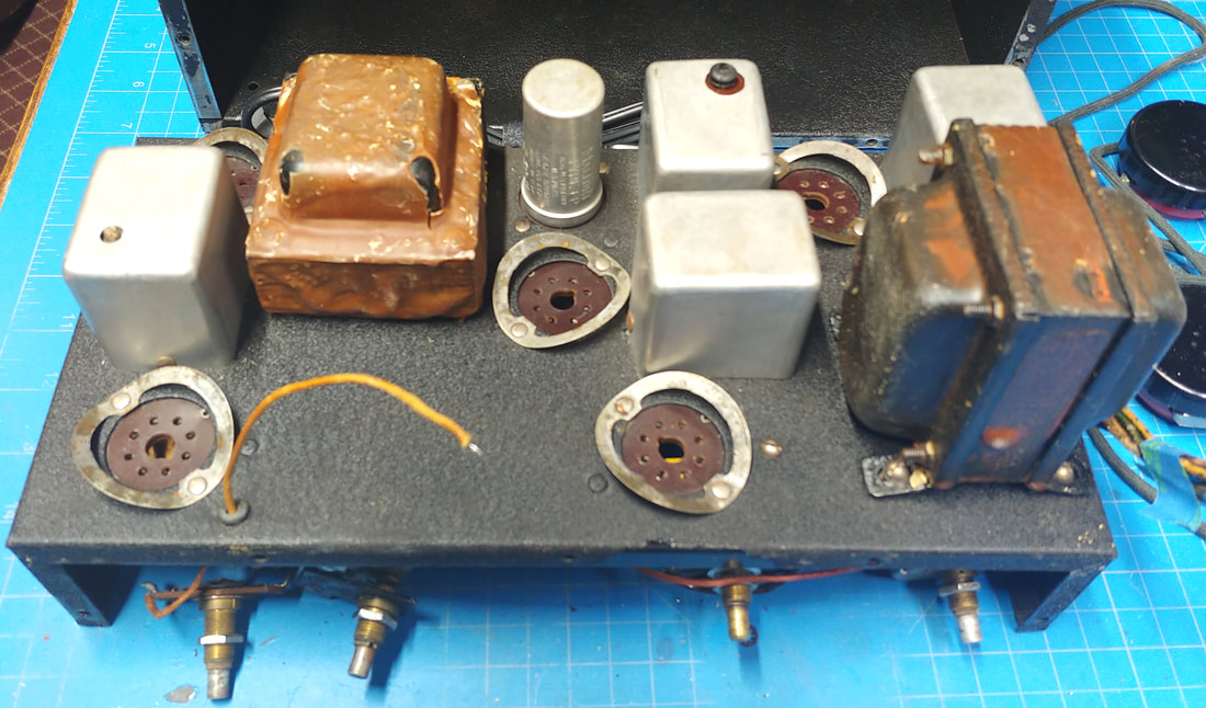
Inside, the chassis is painted in a black wrinkle finish which is still in good shape. It uses a 6X5 rectifier, plus two 6C5's in the audio and mixer section, and two 6SK7's as oscillators.
I didn't pay close attention to the chassis paint until I found my 561 generator, which also has a black wrinkle paint job on its chassis. I accidentally discovered it's really a chrome chassis that's been repainted and now that I've looked closely at the 563 chassis, I see it is also chrome under the paint. Maybe that was part of "militarizing" the set. Also, the brown color of the transformers is a waxy coating, which none of my other Supreme gear has, and could have been a military requirement, too. |
|
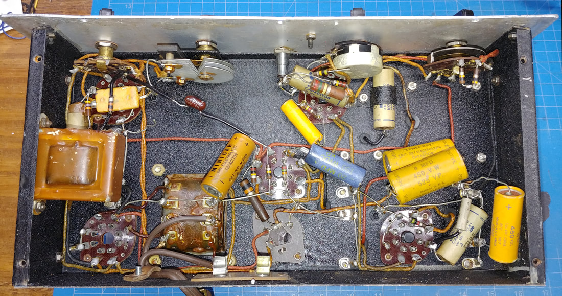
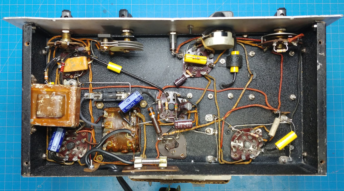
Under the chassis it's obvious somebody has tried to repair it in years past, but it doesn't appear they really knew what they were doing. Multiple electrolytic capacitors have been tacked into the circuit, presumably to try to cure hum issues, but they never bothered to disconnect the old, bad electrolytics first. And the old electrolytic can is definitely bad because it's been leaking.
There's also components hanging free on one end, many that were tack soldered, some that just fell off, and some that are the wrong values. Not much chance this was a reliable or even working piece of test gear with this kind of workmanship. |
|
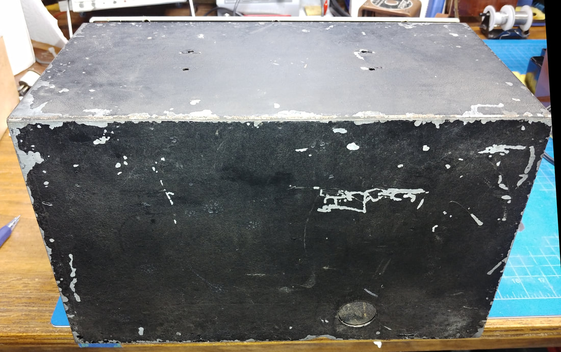
The black wrinkle finish cabinet is pretty beat up, so it will get a new paint job as soon as I can get to it.
|
|
|
What's under those aluminum cans - besides coils and capacitors, these two cans each have a 50KΩ resistor that I replaced. One measured 57KΩ, not too terrible, but the other one was 118KΩ.
|
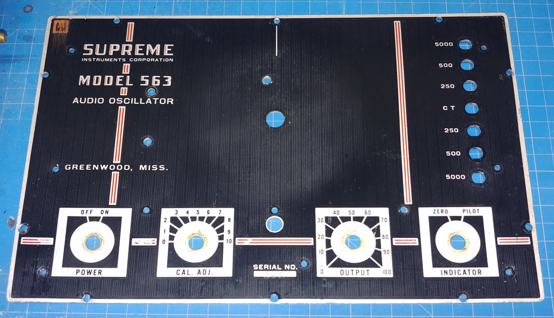
I pulled the front panel to touch it up and to straighten up the chassis. The panel is also in need of some straightening, but I have to be careful not to damage the paint.
In getting the panel off I broke 3 of the 4 front panel chicken head knobs. The set screw threads were so rusted into the Bakelite they had pretty much become one with it, and there was no getting them out. The set screw heads snapped off which broke the knobs. However, the breaks were fairly clean so I was able to epoxy them back together. |
|
The chassis without the front panel. The only paint loss on the chassis was along the front mounting flange. I also had to straighten the two vertical flanges, which were bent outward, causing the front panel to stick out away from the chassis.
|
|
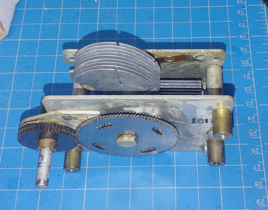
The tuning capacitor and vernier gear were cleaned and lubricated.
|
|
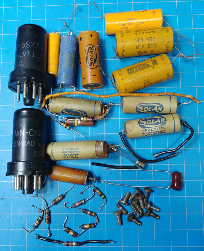
The parts replaced so far include two 6SK7 tubes, which were both weak. I also replaced 3 electrolytic filter capacitors (2 10uF caps in the can, and one 8uF at the 10KΩ resistor, (there are an additional 3 in the photo because someone kept adding them to the B+ line), plus 2 small electrolytics that were across cathode resistors, 10 resistors (there are more than 10 shown because some extra resistors had been paralleled or added in series), and 5 paper capacitors (1 had been replaced with a radial film cap, but I changed it to an axial).
There was another oddball component hanging by one lead that looks like a hollow capacitor with a resistor running through the core and a screw in the end. I have no idea what it was for, but it doesn't appear to belong in this set. One non-original part I left installed is the front panel neon pilot lamp. It's stamped Japan on the bottom so it's certainly not original to a piece of WWII era gear, but I don't have anything better to replace it with right now, and it works. When I come across a more original lamp I'll swap it out. |
In the good old days components had nice long leads for point-to-point wiring, but not so today. I had to extend the leads on two capacitors to be able to reach their tie points. One capacitor that is clamped to the chassis has one lead that goes through a chassis hole to a coil on the top side, while the other lead wraps around the output control and ties to the top terminal. I had to extend both of those leads.
|
The chassis after replacing all the bad components. This unit already has an AC line fuse so no real need to rewire the AC input. Initial testing went well, didn't let any smoke out, and I only see one issue - the B+ voltages I'm measuring are higher than shown on the 563 schematic, yet everything is working.
I found two different 563 schematics. One is undated and looks like it came from a trade journal or book. The other is a genuine Supreme schematic dated 5-30-45. The two schematics are mostly the same and list the same DC voltages. |
The B+ out of the filter choke on the 561 generator schematic is +250VDC, but the Supreme 563 schematics claims the B+ out of the choke is only +135VDC. None of the DC voltages I measured match these schematic voltages. The Supreme schematic claims that 300VAC on the full-wave 6X5 rectifier plates only gives +137VDC out at the cathode. That would be one heck of a voltage drop across the tube. The DC output actually measures 365V. I added a 60Ω 5-watt power resistor in series with the power transformer primary to lower the voltage to around 110VAC. This brought the B+ down to about 350VDC.
The only correct voltage marked on the schematics is the AC voltage at the 6X5 plates. I also measure 300VAC on each plate to ground. And just using some simple ohm's law shows the other schematic DC voltages aren't correct or even in agreement with each other, so the only explanation I see is that the voltages on the 563 schematics are in error.
I also installed a fuse in the power transformer B+ high voltage winding, from the center tap to ground, because 6X5 rectifiers have the reputation of the cathode shorting to the heater, which shorts the B+ to ground and can potentially burn out a power transformer winding.
There is one extra component that's not on the schematic. It's an old style 150pF ceramic/mica wafer capacitor in the fixed oscillator circuit, and it is neatly soldered so it could be original. It's definitely not one of the tack-soldered add-ins.
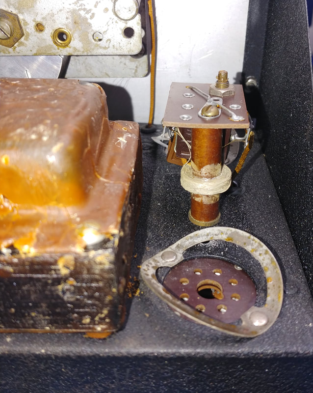
Checking the oscillator frequencies I discovered they are are running in the 193KC range, not 209.5KC as specified in the alignment instructions. I tried adjusting them but they top out out at around 194KC. This made me suspicious of that extra cap in the fixed oscillator circuit so I removed it, and now it can be tuned to 209.5KC. But the variable oscillator is still at 193KC, so I removed its shield can again to see what cap is in it.
The only correct voltage marked on the schematics is the AC voltage at the 6X5 plates. I also measure 300VAC on each plate to ground. And just using some simple ohm's law shows the other schematic DC voltages aren't correct or even in agreement with each other, so the only explanation I see is that the voltages on the 563 schematics are in error.
I also installed a fuse in the power transformer B+ high voltage winding, from the center tap to ground, because 6X5 rectifiers have the reputation of the cathode shorting to the heater, which shorts the B+ to ground and can potentially burn out a power transformer winding.
There is one extra component that's not on the schematic. It's an old style 150pF ceramic/mica wafer capacitor in the fixed oscillator circuit, and it is neatly soldered so it could be original. It's definitely not one of the tack-soldered add-ins.
Checking the oscillator frequencies I discovered they are are running in the 193KC range, not 209.5KC as specified in the alignment instructions. I tried adjusting them but they top out out at around 194KC. This made me suspicious of that extra cap in the fixed oscillator circuit so I removed it, and now it can be tuned to 209.5KC. But the variable oscillator is still at 193KC, so I removed its shield can again to see what cap is in it.
|
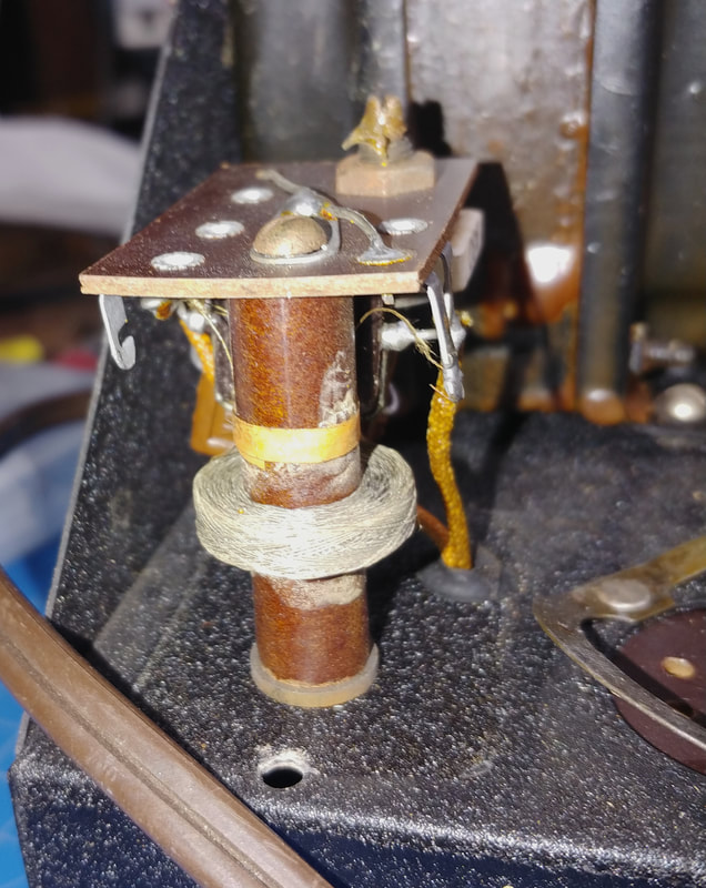
Pulling the can off the oscillator coil is where I did a really stupid thing. I forget to remove the screw securing the coil to the chassis so the coil could move freely, and when I pulled the can off, the riveted "screw" at the can's bottom raked across the edge of the coil and broke several of the tiny wires. I was kicking myself the rest of the day for being so careless.
|
|
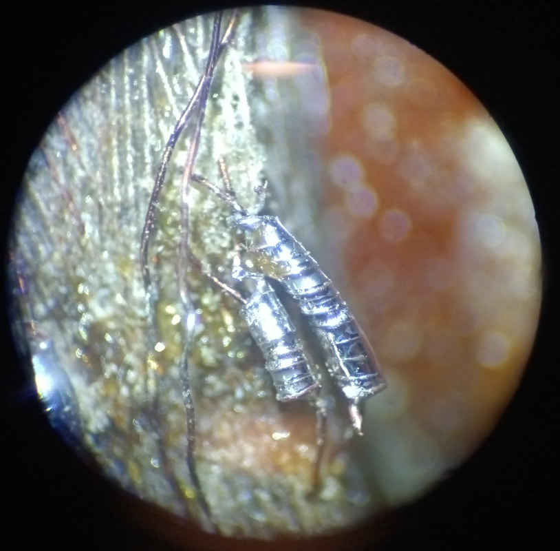
After several hours of "surgery" under a microscope the broken wires were repaired. Not exactly sure what guage the coil wire is but it's as fine as a hair. For comparison, the wire for the repair "springs" are single strands pulled from a 26AWG stranded wire. The springs were formed by wrapping them around one strand pulled from a 14AWG stranded wire. The photo is a shot through one of the microscope eyepieces, showing two of the four repairs. The final step was to coat the fixes in bees wax to protect and insulate them. Thank God I was able to repair it.
|
Checking the mica capacitor, which was the reason for opening the coil can in the first place, it is .001uF as shown on the schematic, so it should be oscillating around 209KC, but it's not. It seems to test OK but I replaced it with another .001uF mica cap, and the frequency went up to about 230KC, which is a bit too high. An extra 330pF capacitor added across the 5KΩ cathode resistor under the chassis brought the frequency down to the 209.5KC range. The original problem might have been the .001 cap or a bad solder joint between the cap, the coil and the trimmer, but I'm not putting it back in to test my theories.
So it looks like there was a problem in the past with the variable oscillator frequency. It was too low at around 193KC and apparently whoever worked on it couldn't figure it out, so they added the extra cap to the fixed oscillator to bring it down to 193KC too. If I hadn't found the original schematic and the alignment instructions, I would never have suspected it was off frequency, that there was a problem in the variable oscillator, and that someone changed the fixed oscillator frequency to "fix" it.
So it looks like there was a problem in the past with the variable oscillator frequency. It was too low at around 193KC and apparently whoever worked on it couldn't figure it out, so they added the extra cap to the fixed oscillator to bring it down to 193KC too. If I hadn't found the original schematic and the alignment instructions, I would never have suspected it was off frequency, that there was a problem in the variable oscillator, and that someone changed the fixed oscillator frequency to "fix" it.
|
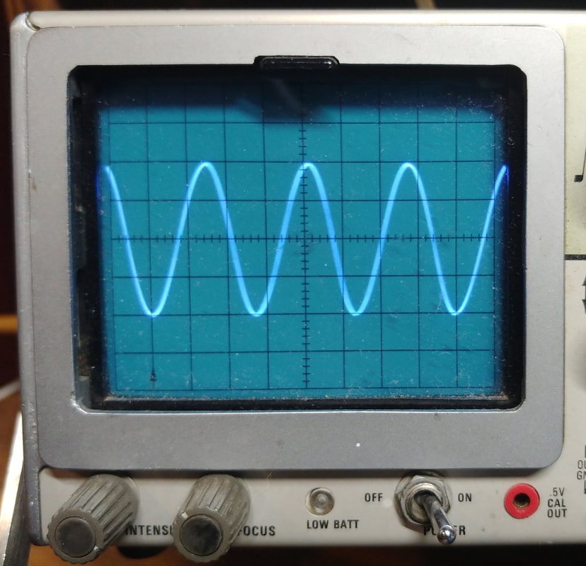
Both oscillators are now running on the correct frequency, and the generator output is a clean sine wave. After a short warmup the output is very stable. I can zero beat it, and all the other components now match the schematic.
The screen grid resistor on V4 (6SK7) was a non-original 300KΩ. There's no value listed on the anonymous 563 schematic, but Supreme's schematic says it's 750KΩ, which also matches the 561 schematic, so I replaced it. I didn't have a 750KΩ on hand so I used a 680KΩ and it works fine. |
|
As far as alignment goes the objective is to set the two generators on the same frequency when the front panel dial is set to 0 and the Calibration control is set to mid-range at 5 (half capacity). This is the Zero Beat position. Then when the main dial is rotated the audio will vary from 0 to 15KC.
I found I needed to set the hairline on the front panel about a 1/4 to 1/2 an inch to the right of the reference mark on the dial to get the dial to track reasonably well, as mentioned in the note about the #5071 capacitor in the alignment instructions. The exact amount to tweak this setting can be determined by observing the dial while checking the frequency with a counter. |
|
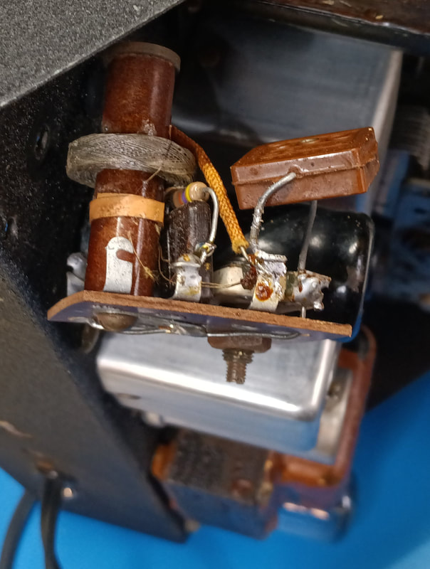
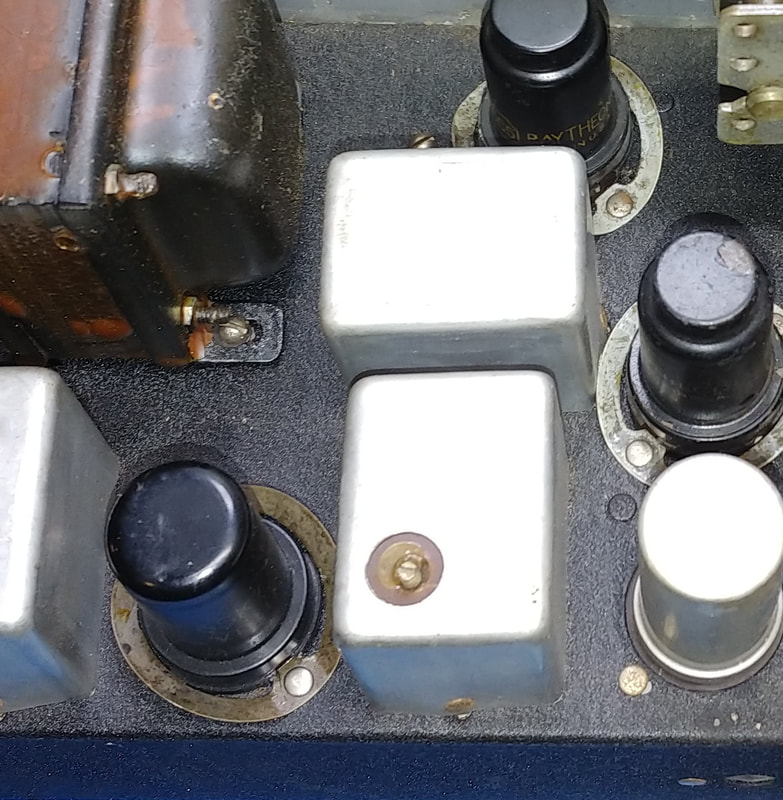
Beware the adjustment screw on the metal can in the photo. It has B+ voltage on it. It is not grounded like the other two adjustment screws. In the 561 a different trimmer capacitor is used, with an insulating washer on the screw so that it is not "hot".
The steps for zero beating the oscillator in use are: - Set the main tuning dial on 0 - Set the Pilot/Zero switch to Zero. - The Zero lamp should illuminate. If it doesn't then either the oscillators are already in a zero beat condition (this can be checked by simply turning the Calibrate control) or the Output control needs adjusted to a higher level until the lamp illuminates. - Adjust the Calibrate control for zero beat. - The Pilot lamp will extinguish when zero beat is achieved. - Switch the Pilot/Zero switch back to Pilot. |
The oscillator is now calibrated and ready to use.
|
All back together again. The top handle was already missing when I bought the set and I haven't found a replacement yet.
|
Page created 3/17/2021
Last update 9/8/2022
Last update 9/8/2022
