B&K Model 290 Hi-Low FET Extended Range Multimeter
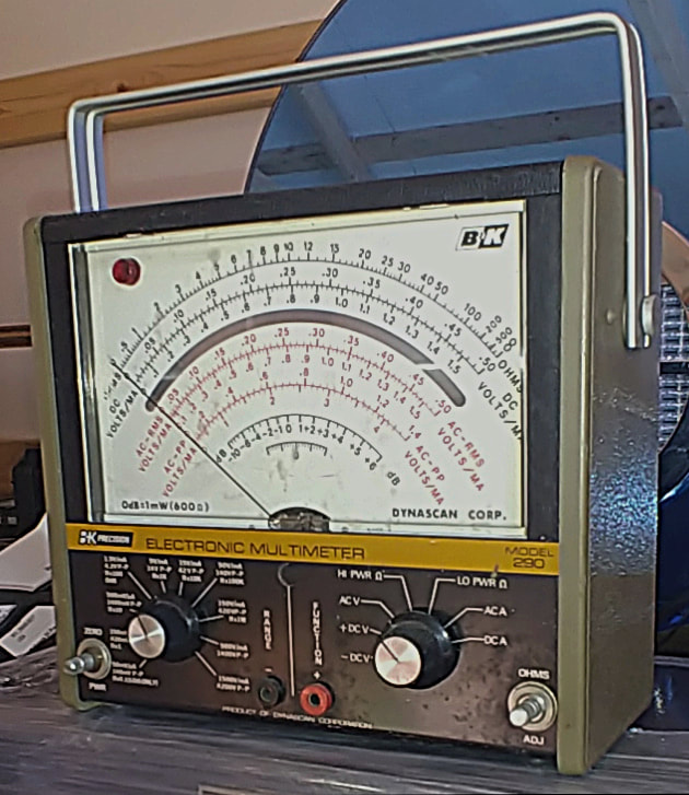
I have a number of VOMs, VTVMs and DMMs that I use on a regular basis. The reason for a variety of meters is each has some feature or function that's special to it, or maybe just more to my liking, than those on the other meters. Some of my meters have nixie tube readouts, some are analog, some are 75 years old, and some are modern digital wonders. And now I have one more, a new to me B&K Model 290 Extended Range FET Multimeter.
|
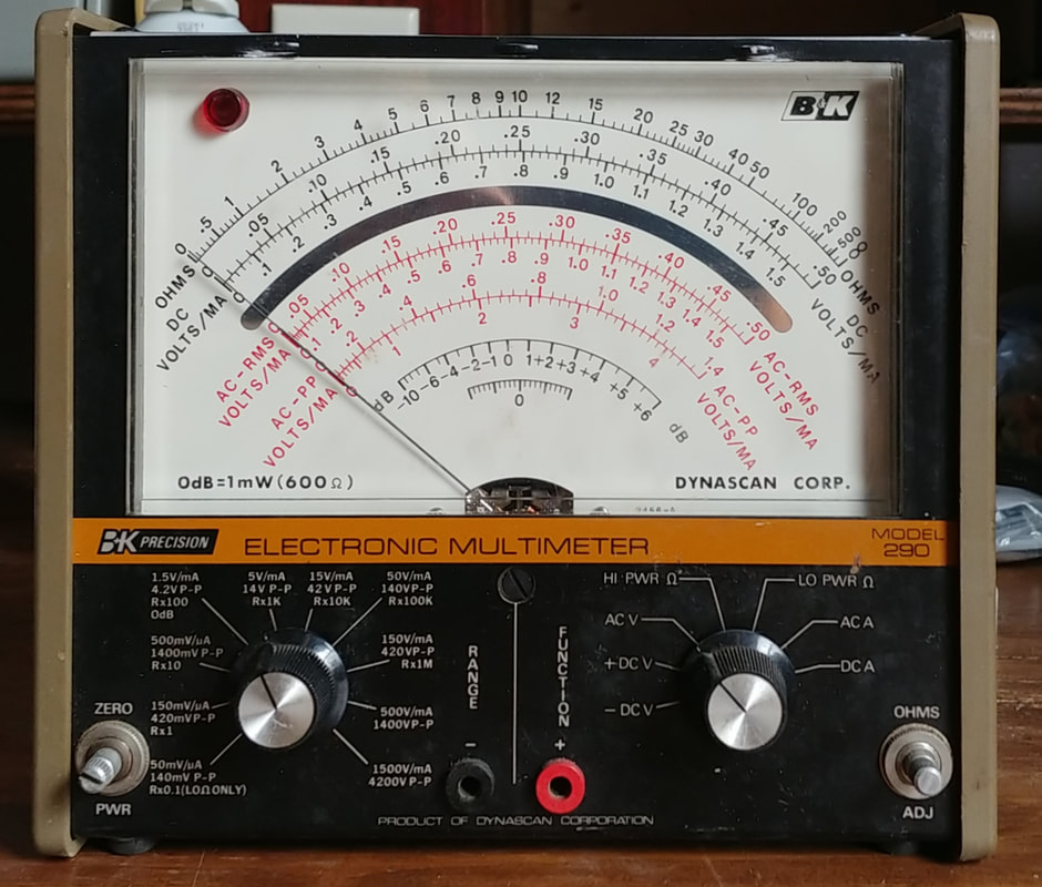
The 290 has several features that I find useful and I think overall it's a gem of a meter. I especially like the easy-to-read 7" mirrored analog meter movement. And it has 15MΩ input impedance and voltage ranges as low as 50mV FS. The ohmmeter has Hi (1.25V) and Low (33mv/42mv) voltage functions for troubleshooting transistors and logic components, and a R x 0.1 low ohms range with 1Ω at center scale.
|
|
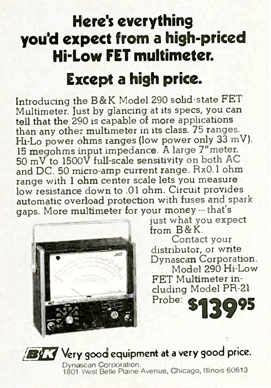
The first reference I found to the B&K model 290 is in a January 1974 magazine ad. It was advertised at the "low" introductory price of $139.95, still a princely sum for a poor electronics student like myself at the time.
For a little perspective on the price, as I recall back then I could get a couple of burgers, fries and a soda from McDonalds for about 98 cents. That's a lot of burgers. |
|
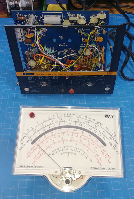
The mirrored 7" meter face. The only meter I have larger than this one is the 9" Hickok 225K. It's case is huge so it sits on my bench's top shelf, but the smaller footprint of the 290 will let it set closer to my work. Big analog movements are perfect for much of what I do on the bench (not that digital meters don't have their place, too).
|
|
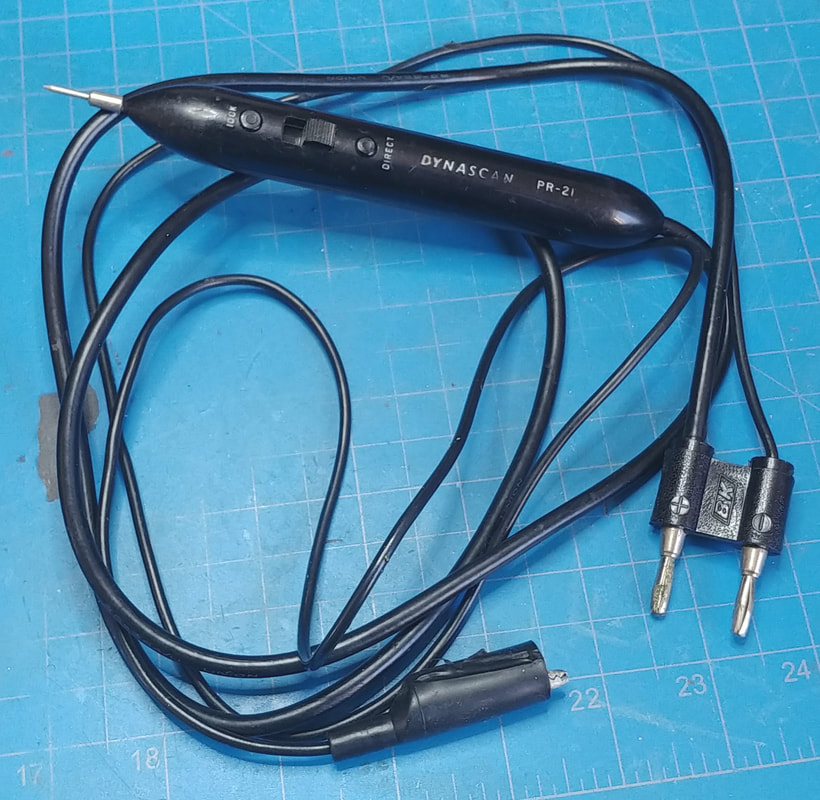
The meter was missing its input probe, not an uncommon situation for meters with removable probes. It would be relatively easy to build a new one, but I managed to find an original PR-21 probe online.
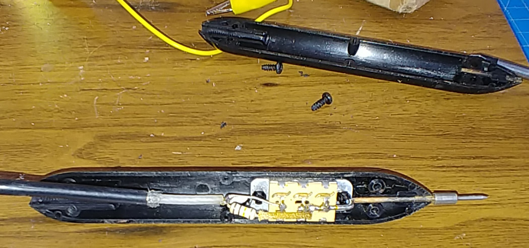
The probe contains a 100KΩ resistor in series with the tip for DC measurements, and a switch to bypass it for a direct connection for AC and Ohms. It also has a shielded cable due to the sensitivity to noise on the lowest ranges. |
|
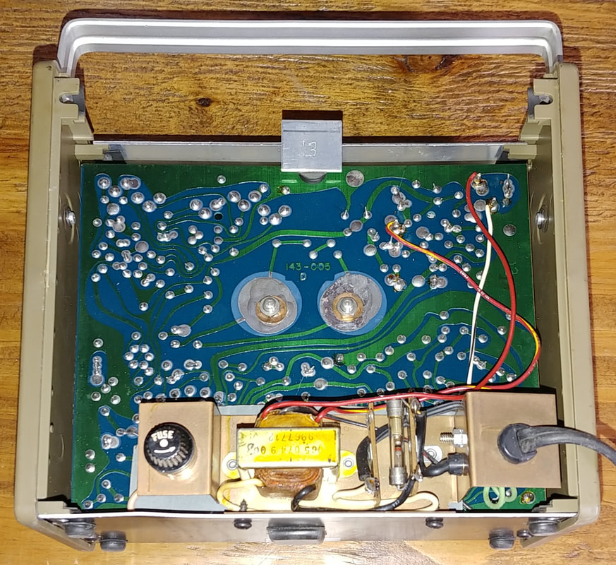
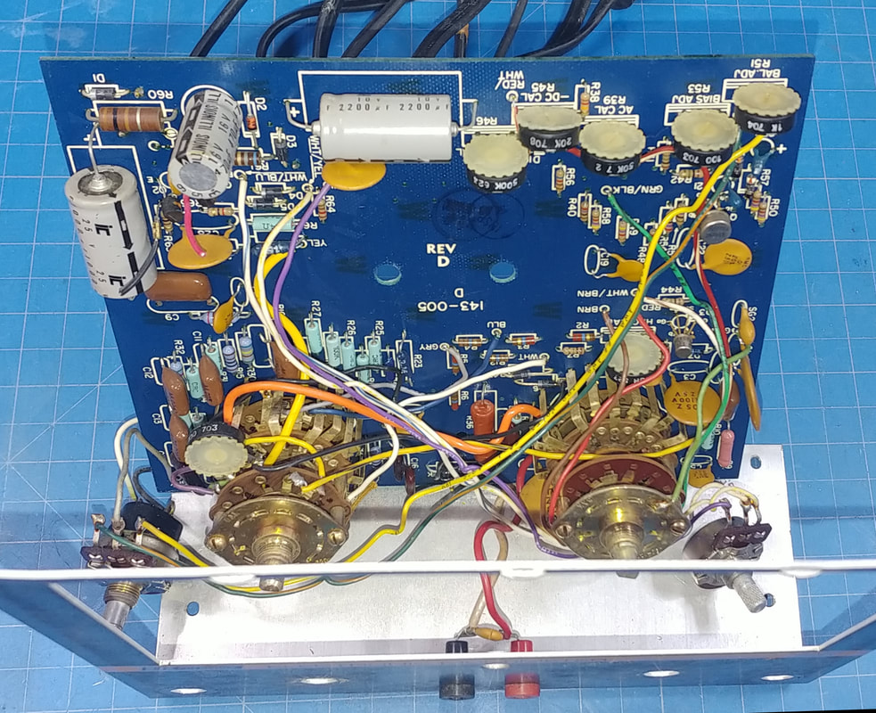
So far I don't see any obvious parts that have been replaced inside and it appears to be in original condition. The instrument is fairly light weight for its size. The sides are plastic and the case top and back are vinyl covered aluminum. It doesn't have the build quality of a military or high-end commercial meter, such as an HP, but it does offer extended ranges not usually seen on less expensive equipment, or even some high end meters.
It's meant to be a bench meter so it doesn't have any heavy batteries inside to add weight, and it's powered by a zener regulated AC power supply. |
|
Disassembly is pretty straight forward. The rear case is removed, then the side panels, the front panel knobs and hardware, and finally the PCB is pulled to remove the meter movement.
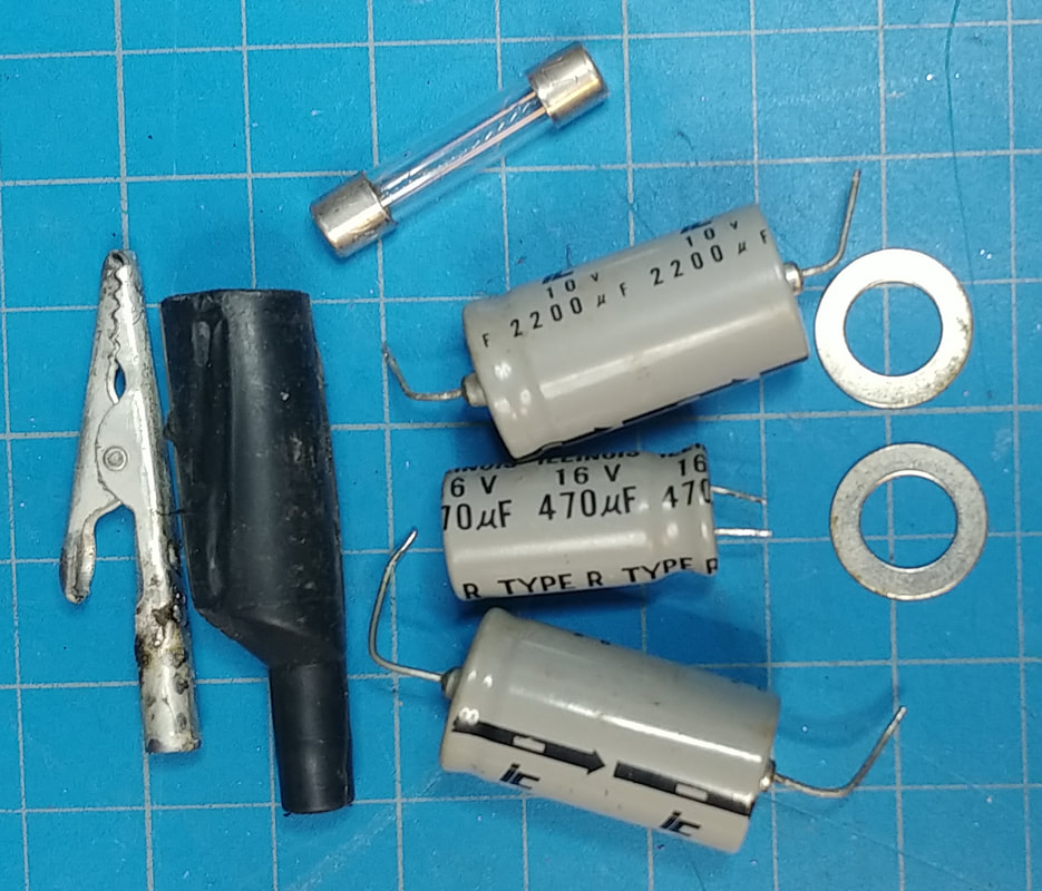
This meter's PCB circuit ground is isolated from the case AC ground. So, the common test lead is not the same as AC ground. And there is a fuse, located on the rear at the power supply, that fuses the common test lead. At first glance this fuse would appear to be the AC line fuse for the power supply, but that fuse is actually inside on the power supply sub-chassis. As received, the meter wouldn't measure anything, but it was because the common lead's fuse was blown. After replacing it, all functions appear to work except adjusting the Hi Ohms. But after a quick calibration It's now working fine. At first I was worried that maybe someone did something stupid like measuring the AC line with the function switch on Hi Ohms. But it was just out of calibration. |
And speaking of calibration, the first step is adjusting the Bias. To do this an external meter is connected between common and the meter movement's + terminal, but the polarity isn't marked anywhere except on the rear of the movement, and to see it you have to pull the movement off the PCB. On most meters I've seen, + is the left terminal looking at it from the rear and this meter is the same.
|
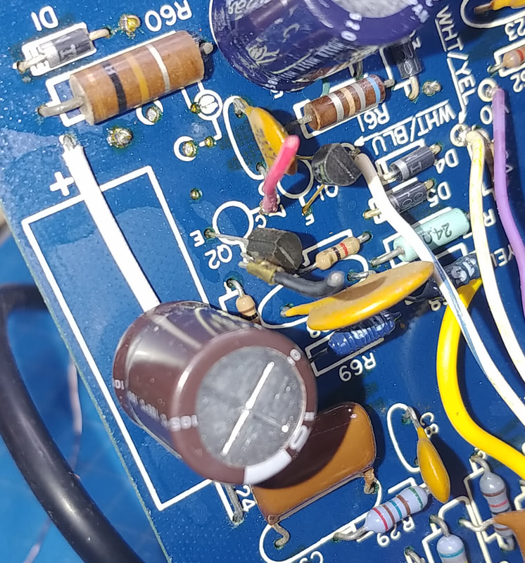
The neon power indicator lamp shown on the schematic has been converted to an LED that is connected in series with the collector of Q2. The cut-off red and black wires in the photo went to the LED, but I had to snip them to separate the meter movement from the PCB, because the LED had been inserted inside the red plastic "jewel" on the movement and was stuck. I think this is a factory mod, although I'm not 100% certain, but I'll leave it installed.
|
|
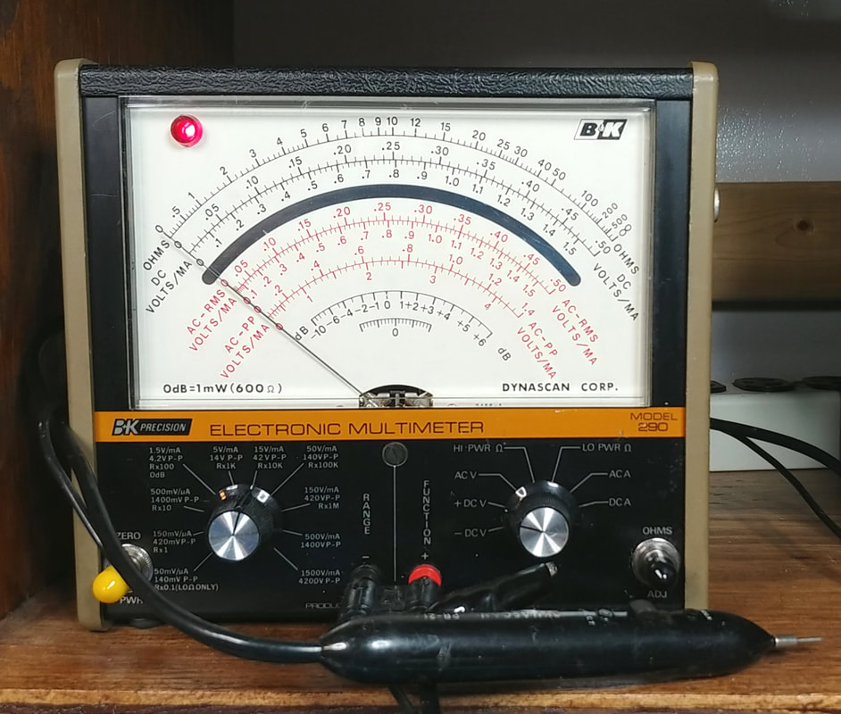
On the work bench shelf and ready for use. The calibration went according to the manual, and the accuracy is very good in every range I checked, still within the original specs. I didn't need to replace any resistors at all. The scales on this meter are so easy for me to read that I know it's going to see a lot of use on my bench.
|
After using the meter for a while the only annoyance I've found is with the PR-21 probe. I thought the probe had a shielded body but turns out it doesn't. I opened it to see what's inside and it's just an unshielded plastic case.
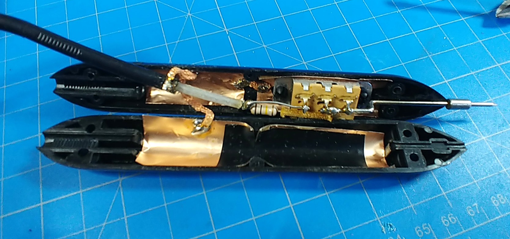
Touching the probe when the meter is on a sensitive range causes the needle to bounce around and even peg at times. I find it most annoying on the 1MΩ range as it can affect the reading, so I lined the probe's inside with copper foil and tied it to the coax shield with copper braid. As a precaution, a layer of tape was placed over the foil that's under the switch contacts so they can't short to the shield. Now the needle doesn't bounce around when handling the probe, as long as I keep my fingers back away from the front tip.
Touching the probe when the meter is on a sensitive range causes the needle to bounce around and even peg at times. I find it most annoying on the 1MΩ range as it can affect the reading, so I lined the probe's inside with copper foil and tied it to the coax shield with copper braid. As a precaution, a layer of tape was placed over the foil that's under the switch contacts so they can't short to the shield. Now the needle doesn't bounce around when handling the probe, as long as I keep my fingers back away from the front tip.
Page created 11/21/2021
Last updated 3/29/2022
Last updated 3/29/2022

