Hickok Model 18 RF and AF Signal Generator
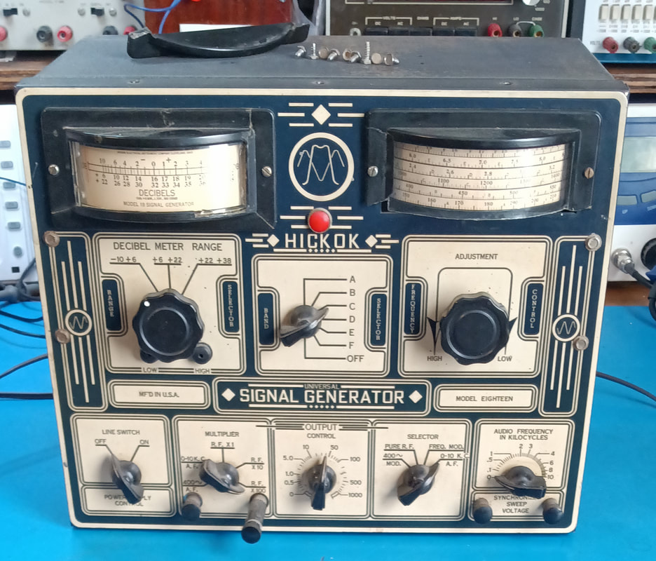
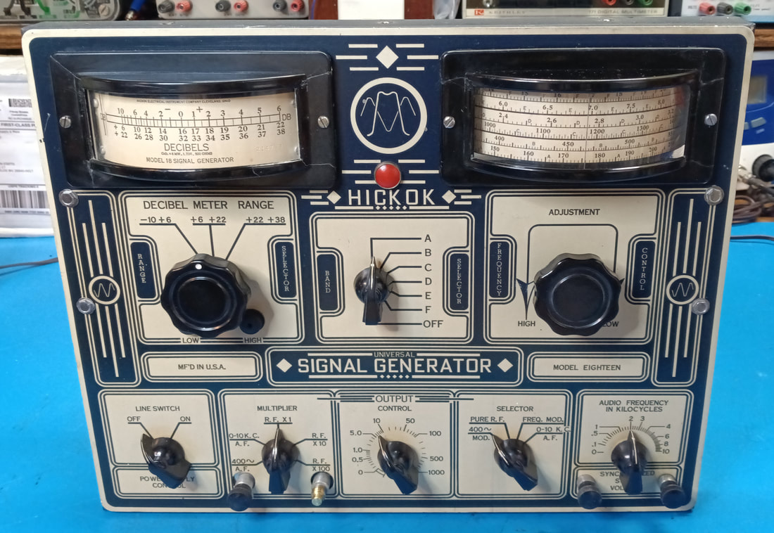
The model 18 is a predecessor to my model 288X generator and dates back to around 1939. It has a lot of the same functionality as the 288X, including an AF generator, RF unmodulated and modulated output, plus frequency modulation and an output meter.
The serial number is 1-4964 and I wonder if the 1 might indicate the year of manufacture. If it does then this would be a 1941 year model.
The serial number is 1-4964 and I wonder if the 1 might indicate the year of manufacture. If it does then this would be a 1941 year model.
|
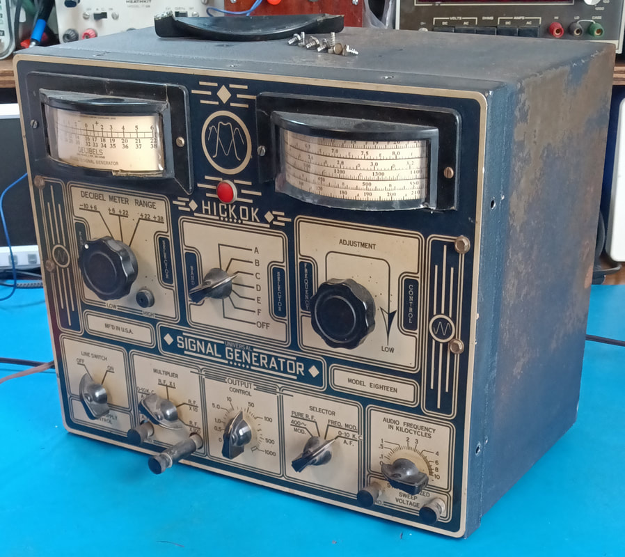
There's a good bit of paint missing on the cabinet so I'll have to repaint it. In the photo the bottom of the frequency dial bezel is laying on top of the cabinet, but at least it was still with the generator.
The bezel of the decibel meter is also cracked in five pieces but has been reglued by someone. I'll probably disassemble the meter to check it all, and see if the bezel needs reglued again. I know there are also two copper oxide rectifiers inside that need checked as well. |
|
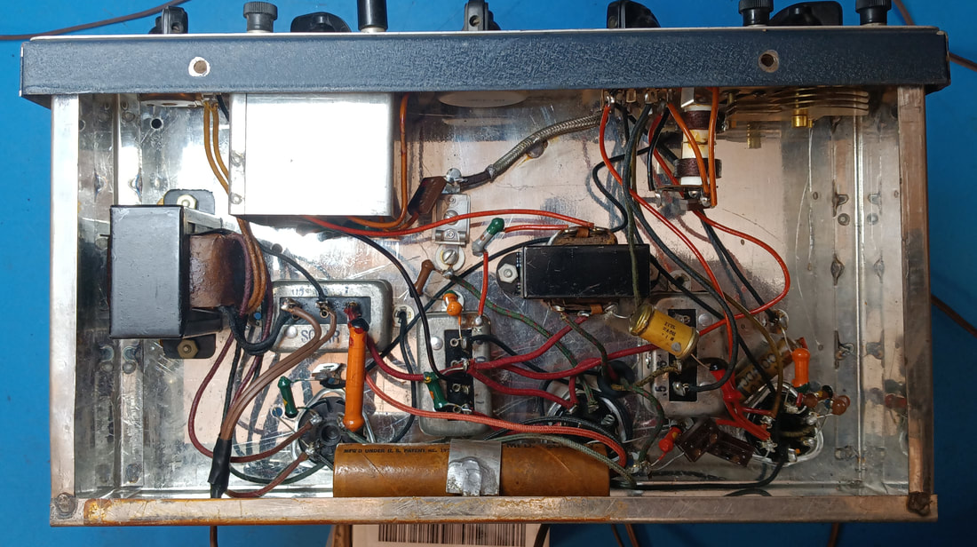
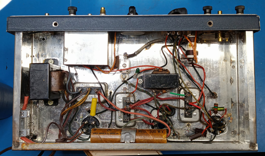
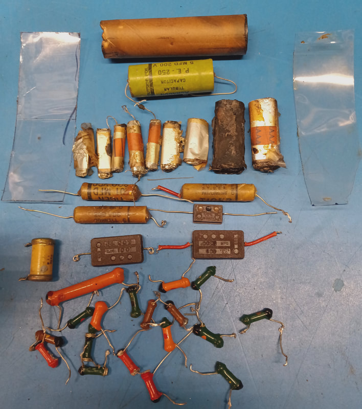
Under the chassis is also clean and so far looks like it's all original except for the power cord. Hickok used some nice looking dog bone resistors in this set, but so far everyone I've checked is out of spec. I've only found two good resistors and they're not dog bones, but I still have a few more to test. Also, all the non-mica capacitors I checked are bad, as are the electrolytics. I still need to check the mica caps, too, but I'll do those as I get to them during the restoration.
|
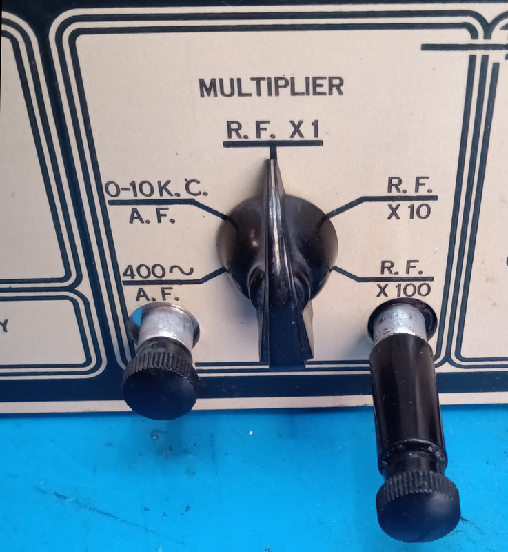
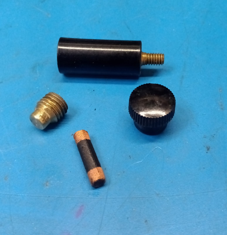
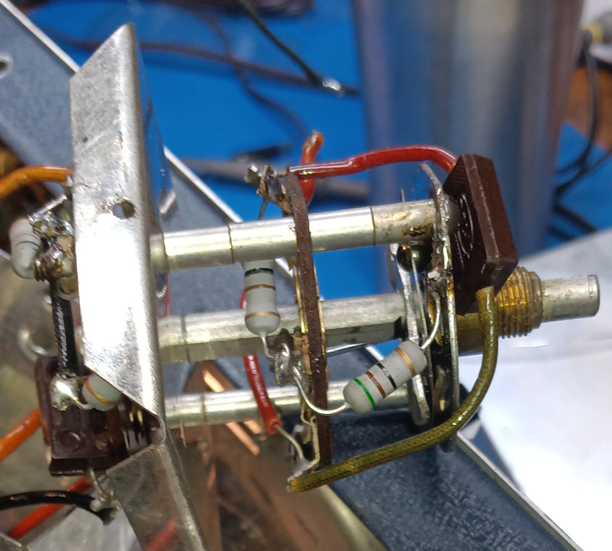
The output binding post on the front panel protrudes from the chassis compared to the other posts. It unscrews from its mounting base and inside there is a carbon resistor, an external attenuator. Looking at the catalog image of a model 18 I don't see this protruding binding post, so it must be an add-on. I imagine there would originally have been a set of attenuator resistors that could be swapped as needed.
|
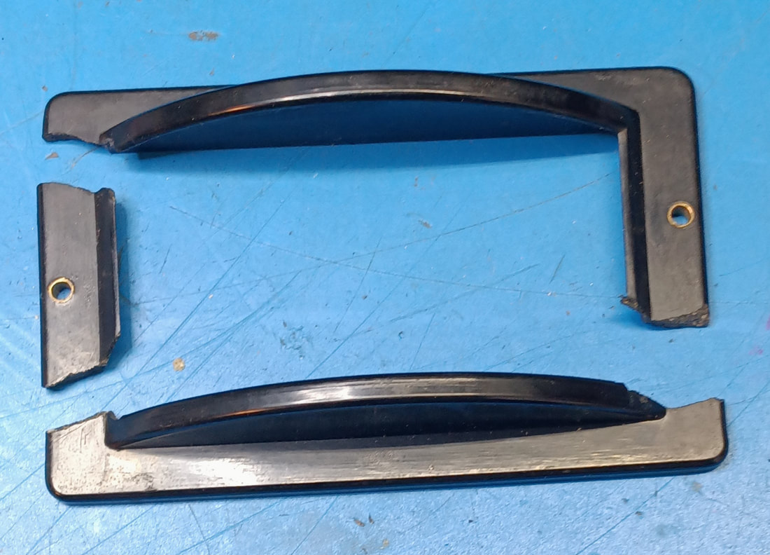
The frequency dial bezel is broken in four pieces. My guess is the generator was dropped on its face at some point since both bezels are similarly cracked. The pieces have been cleaned and the old glue removed and next they will be epoxied back together. Then I need to make a new plastic dial hairline.
I also need to make a new clear plastic "glass" for the decibel meter too. Whoever reglued these bezels in the past also replaced the clear plastic, but they used some thin stock not really suitable for a dial glass. I'll cut some new ones from heavy plastic. |
|
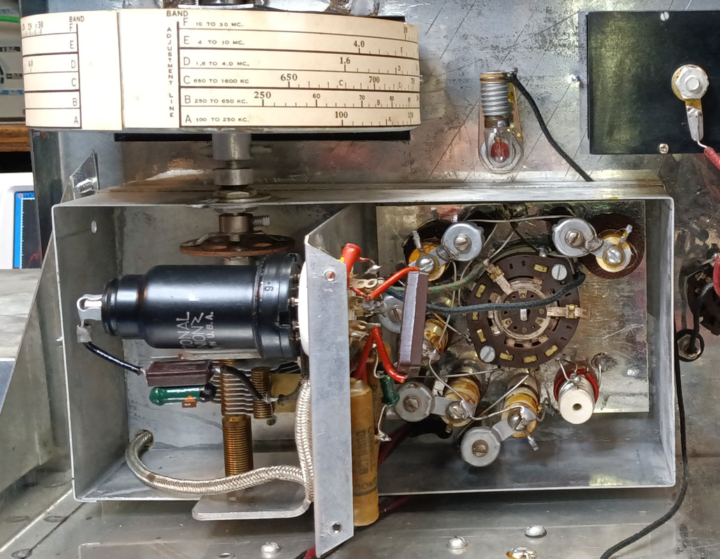
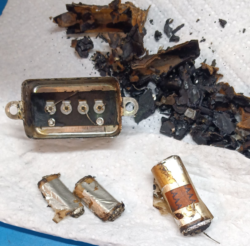
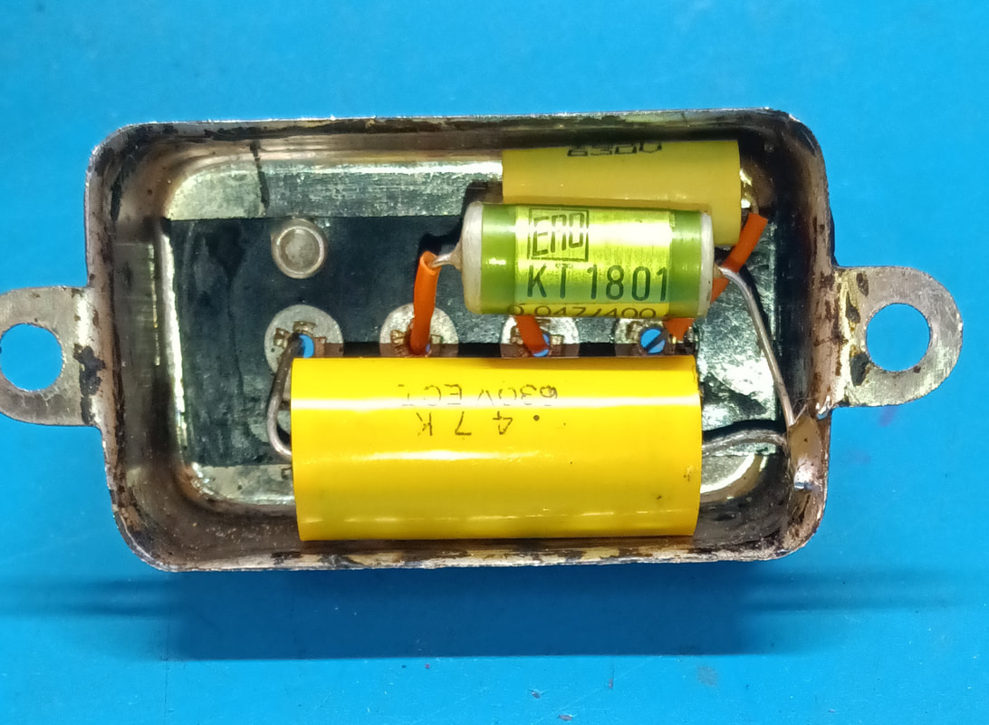
There are three "bathtubs" riveted to the chassis, each with multiple capacitors inside that need replaced. These bathtubs are potted shut, which is a bit of a mess to dig out, but still better than the oil-filled kind. Those I would just dispose of because of the possibilty of the oil having PCBs in it, but these I can rebuild.
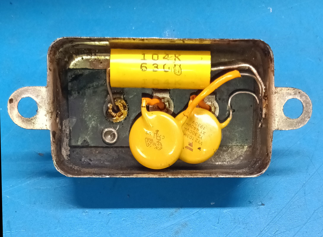
The capacitors inside them are all paper and foil types and are so old the paper insulation in the caps is deteriorating and is now electrically leaky. In one of the bathtubs there are two very leaky "death caps" going from the AC line cord directly to the chassis. |
|
Two of the bathtubs contain a 0.5uF capacitor from the first terminal to ground, a 0.05uF from terminal 2 to ground, and a 0.1uF from terminal 3 to terminal 4.
When I removed the bathtub on the right hand side of the chassis I noticed the 0.1uF capacitor was disconnected on one end. Another 0.1uF ceramic cap had been soldered into the circuit to replace it, so it turns out there was one non-original capacitor installed. After replacing the old 0.1uF cap in the bathtub, I reconnected it back in the circuit and removed the ceramic replacement. |
|
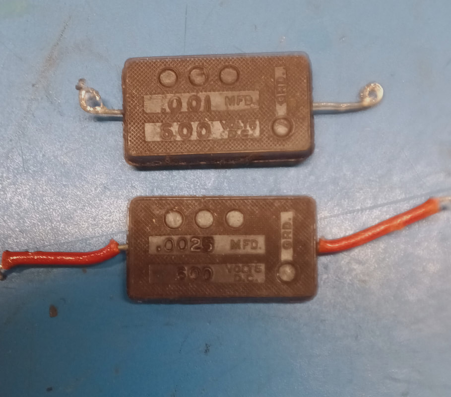
In summary, I've replaced 18 resistors, 13 foil capacitors, two power supply electrolytics, one 100pF mica in the grid lead of the 6J7 RF oscillator which measured only 68pF, and two capacitors that looked like mica caps, but turned out to be more foil capacitors. Also, I replaced the dial "glass" in both the frequency dial and the decibel meter, the power cord was replaced with a polarized one, an AC fuse holder was added, 8 new rubber feet were installed (4 on the bottom and 4 on the back) and lastly, an added-in tubular ceramic capacitor was removed. The tubes have been tested and are all good, so all that's left is the final testing and alignment.
|
|
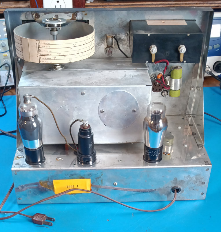
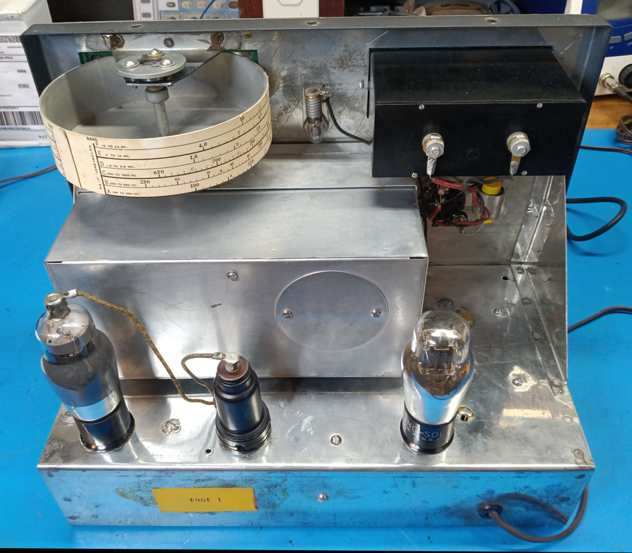
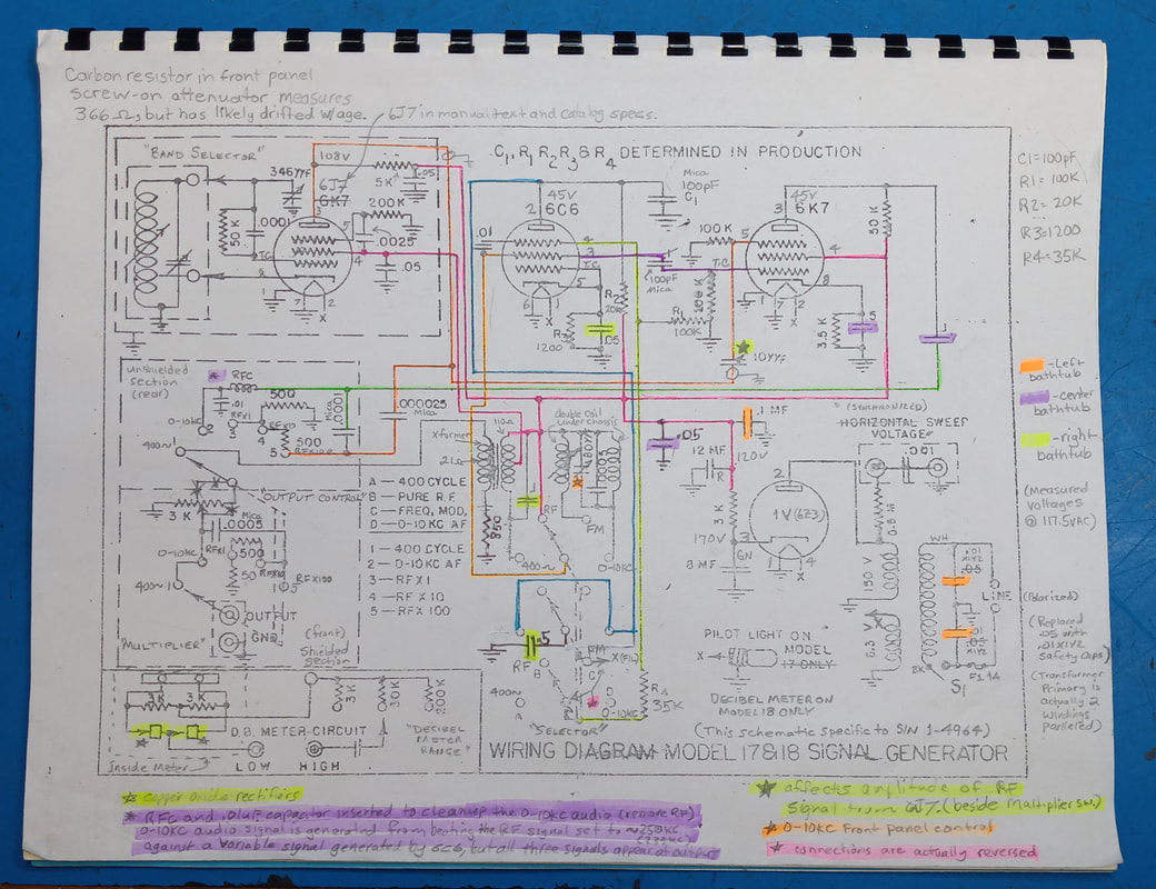
Topside of the chassis is finished and all the tubes tested very strong, but there's one discrepancy. The RF oscillator tube is a 6K7 and is labeled as such on the schematic. However, every other reference in the manual and the 1939 Hickok catalog states the RF tube is a 6J7. The two tubes are similar and I didn't notice any difference in operation, but I still installed a 6J7 instead of the 6K7.
|
|
My edited schematic is specific to this generator, but most of the edits are changes Hickok made. The only mods I added are changing the capacitors on the AC line to X1Y2 safety capacitors which are 0.01uF instead of 0.05uF, and adding a RF choke with a 0.01uF bypass cap to the 0-10KC audio at the "Output" switch to block the two RF signals used to generate the audio frequencies. I also had to add a tie point for this mod.
The audio output was really messy when viewed on an o'scope, although it was putting out an audio signal as part of the mess. The RF choke and capacitor filter out the RF beat frequencies so they will not be injected into anything being tested with the generator. |
It's now back together and working on all bands. I like this little unit but it will probably go to next year's local hamfest, because I have too many good generators already.
Page created 10/07/2023
Last edited 10/31/2023
Last edited 10/31/2023

