
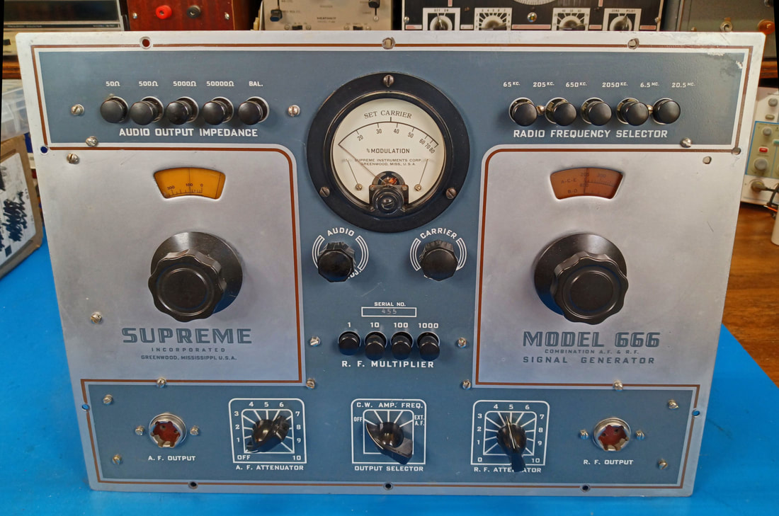
Restoring a Supreme Model 666 Combination AF and RF Metered Signal Generator
The model 666 signal generator is a 1948 update of the model 561 AF/RF generator first introduced in 1939. It has the same functionality as the 561 with a couple of tube updates and a new color scheme.
According to Supreme's service bulletins the model 666 was out of production by the second quarter of 1953 due to parts shortages and government restrictions. I suppose this was due to the war in Korea.
According to Supreme's service bulletins the model 666 was out of production by the second quarter of 1953 due to parts shortages and government restrictions. I suppose this was due to the war in Korea.
|
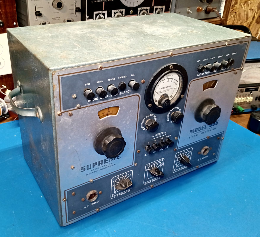
The generator is in pretty good condition considering its age. There's a little rust here and there, but nothing too terrible. Likewise, there are some scratches on the case and front, but again, nothing horrible.
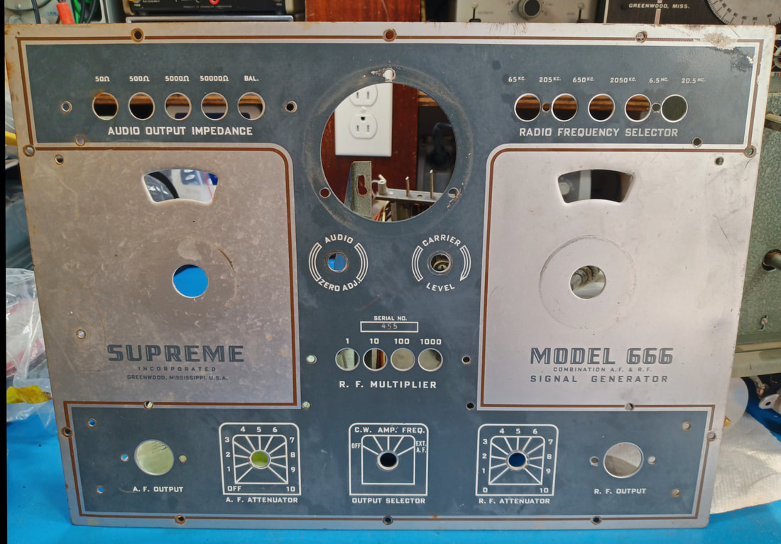
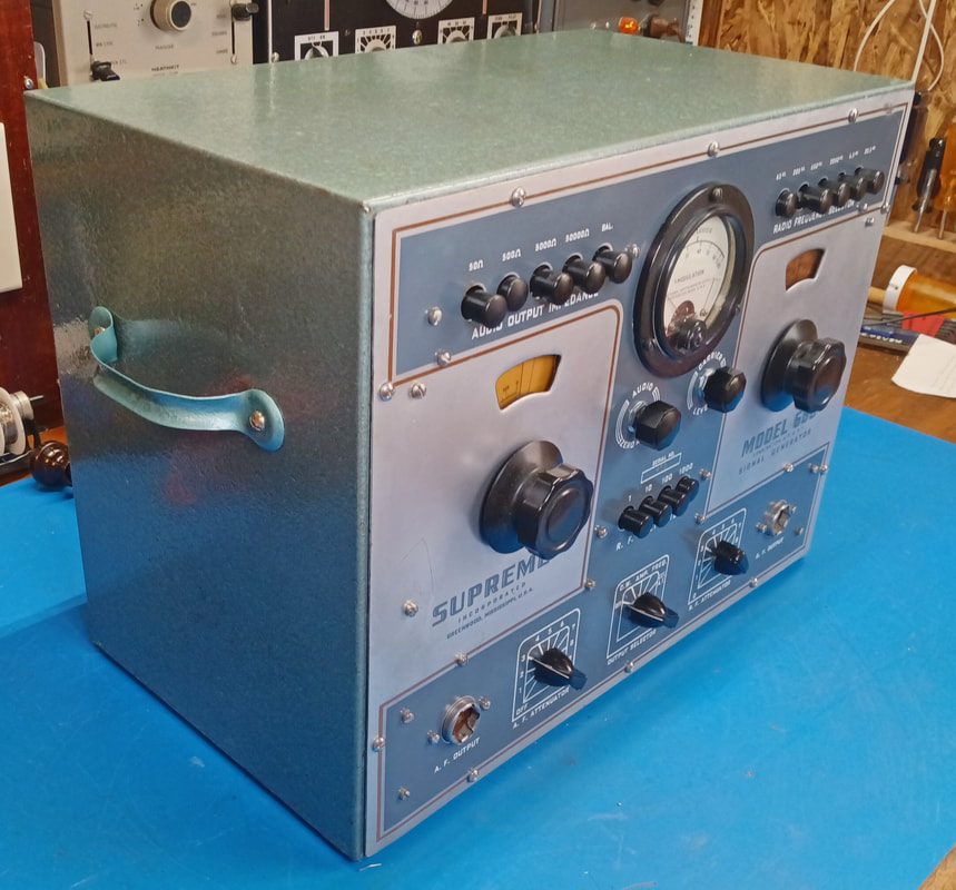
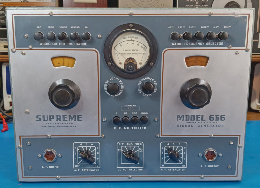
I purchased this generator simply out of curiosity about what Supreme had changed when they updated the model 561 to create this new model. I assumed the paint would be a gray wrinkle finish as advertised for the 561 in their 1947 catalog, but it's actually a hammered finish with a blue-green tint. Supreme called this new finish "Blue Hammerloid" in their 1948 catalog, but it looks more green than blue to me. And the front panel is described as satin aluminum and blue with maroon trim. This generator is serial number 455, and if the front panel was originally made of aluminum then Supreme had changed to steel by the time this one was manufactured. Possibly this was another shortage due to the war. |
|
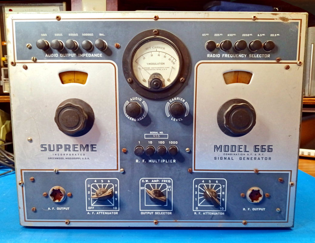
There's nothing missing on the front panel, all the knobs and buttons are there and the controls all move with the exception of the "Audio Zero Adjust" trimmer capacitor, which was stuck. But a little WD-40 and some SuperLube spray fixed that.
|

|
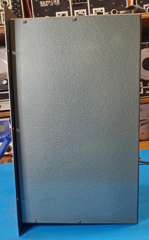
It still has the perforated back panel attached which is good to see. One of my Supreme Audolyzers was missing the back and it took a long time to find one. And once again Supreme ran the power cord through one of the small holes, trapping the back on the cord.
|
|
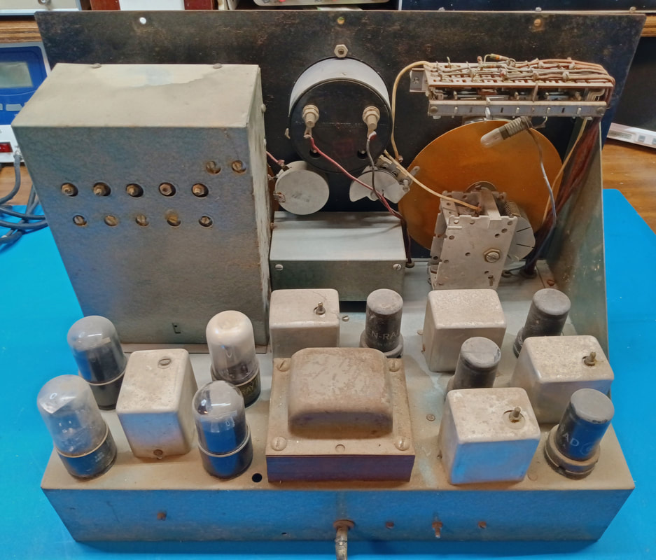
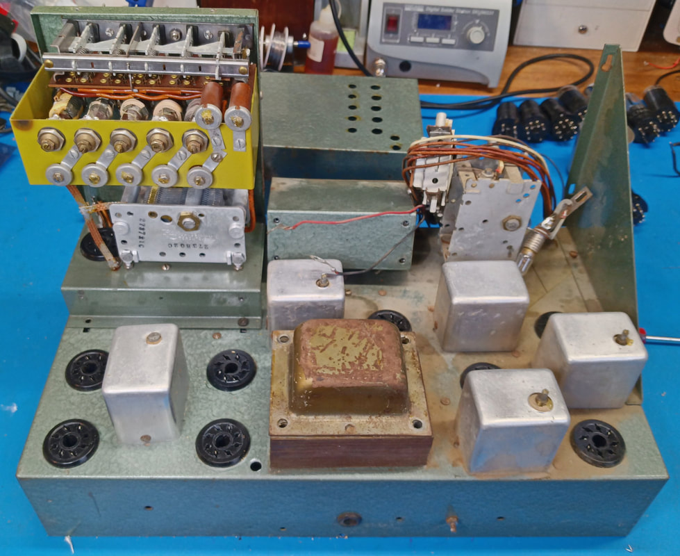
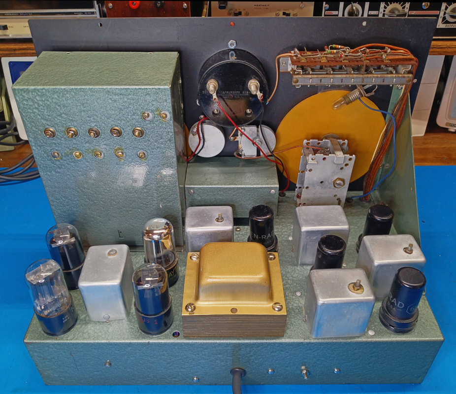
Inside it's dirty but looks like it will clean up nicely. No rust to speak of on the chassis, and it's painted in the same hammered paint as the cabinet. The transformer is rusty and needs repainted, too, but it is a gold-tone color.
|
|
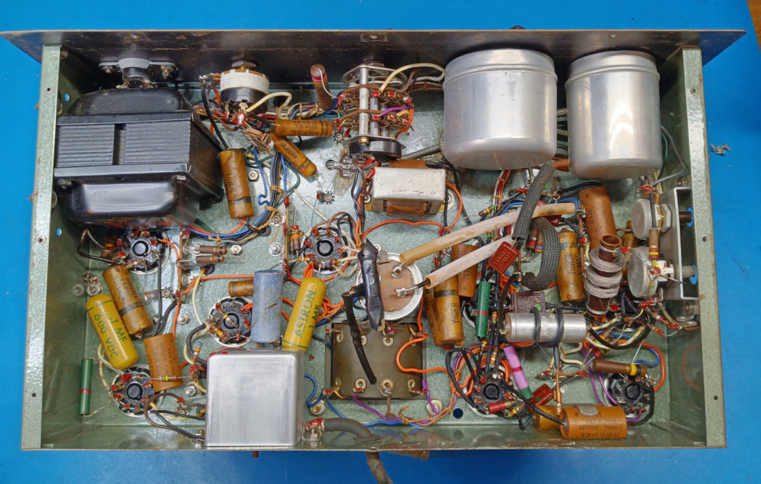
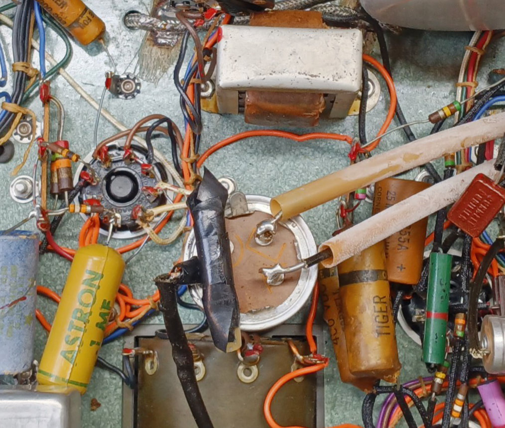
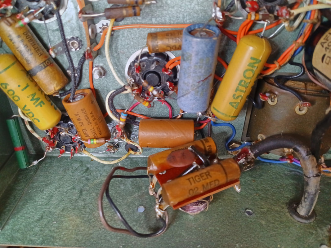
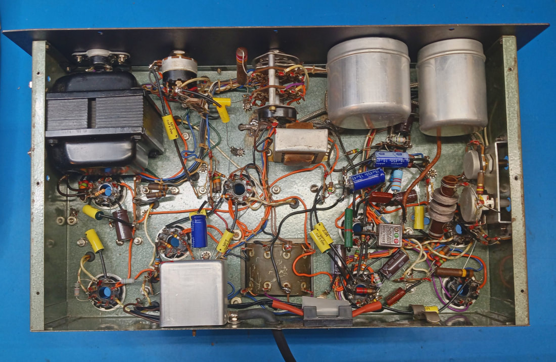
Under the chassis it looks to be mostly original. It has been worked on in the past and someone replaced all the power supply electrolytic capacitors, several waxed paper caps, and a couple of resistors.
Two of the filter caps had been replaced with a multi-section can standing on end. The two yellow plastic encapsulated Astron capacitors don't look to be original either, and may be film or di-film caps. |
|
This is a closeup of the old replacement filter can. It will be removed and replaced with individual capacitors.
|
|
I popped the aluminum cover off the AC power line filter to see if the capacitors were melted down like the ones in the 561. I'm positive they are leaky, considering their age, but they're not melted which is a good sign.
|
|
The front panel was removed to gain access to the dials and the multiplier box, and to allow for easy removal of the RF sub chassis. It also makes it much easier to clean up the top of the chassis and the dials, and the front panel itself. Plus the back has a little surface rust so I will clean it up and refresh the paint.
|
|
Starting to clean the chassis after the removing the front panel. The RF subchassis was checked and cleaned, and three waxed paper capacitors were replaced. All the resistors in the subchassis checked OK.
|
|
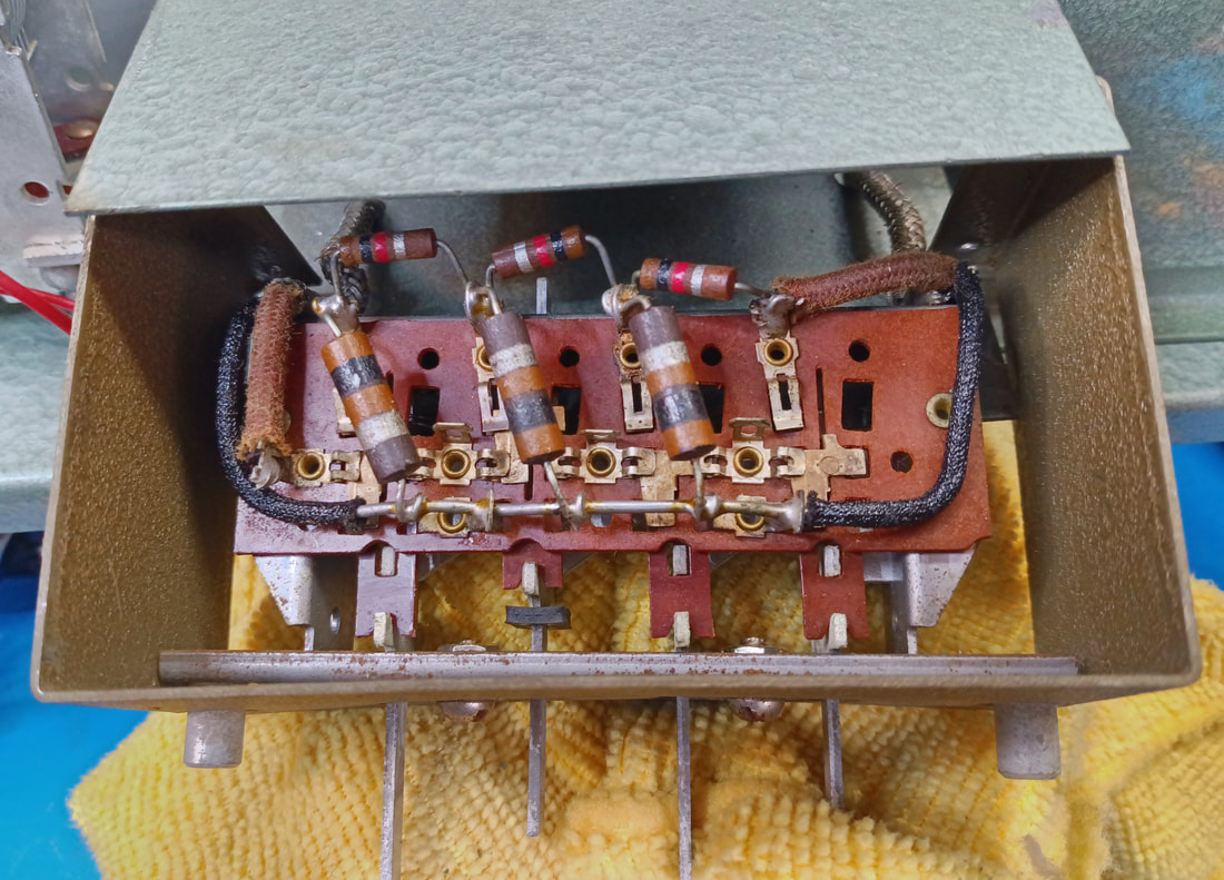
The Attenuator box is the hardest assembly to get access to, so I'm replacing all the resistors while I have it open. All but a couple are out of tolerance anyway. The three 1KΩ resistors are listed as 900Ω on the schematic so that's what I'll use to replace them.
|
|
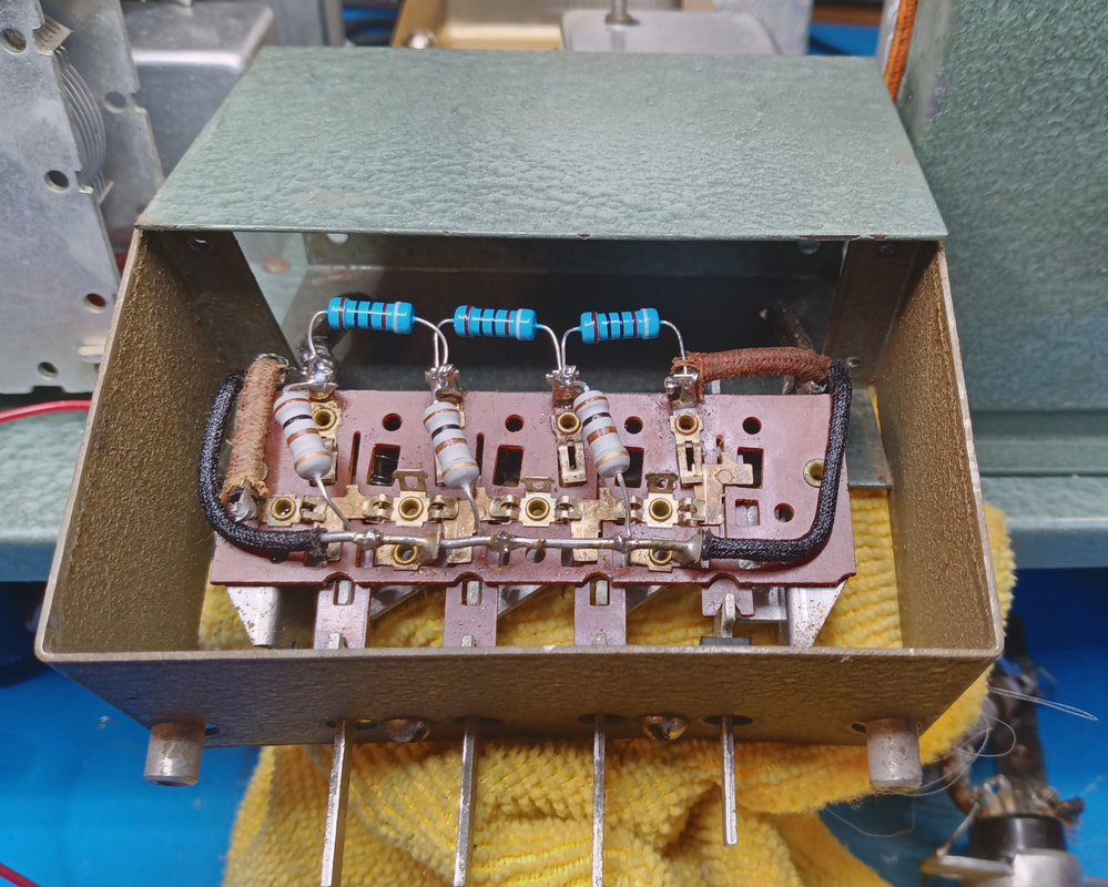
The rebuilt attenuator is ready to be closed up. On the schematic there are four 100Ω resistors, but only three are actually installed from the factory.
|
|
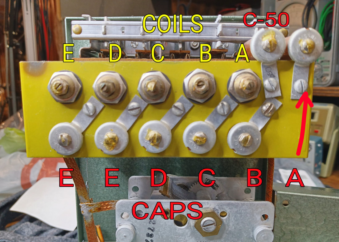
The band coil and trimmer capacitor layout is slightly different from the 561.
Supreme moved the "A" band trimmer capacitor from the chassis, where it was in the 561, up to the RF section with the other band trimmers. Also, the C-50 trimmer capacitor, which was not installed in my 561, is mounted beside the "A" trimmer. The trimmer C-50 across the main RF tuning capacitor is not in the alignment procedure and I'll just leave it as is unless there's an alignment issue. |
|
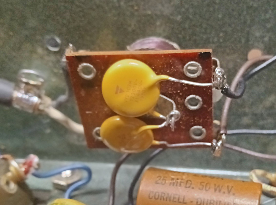
The waxed paper capacitors in the AC input filter have been replaced with X1Y2 safety capacitors. A new shielded power cord has also been installed. A third capacitor was removed because it's not on the schematic and going by the soldering it was not a factory part.
|
|
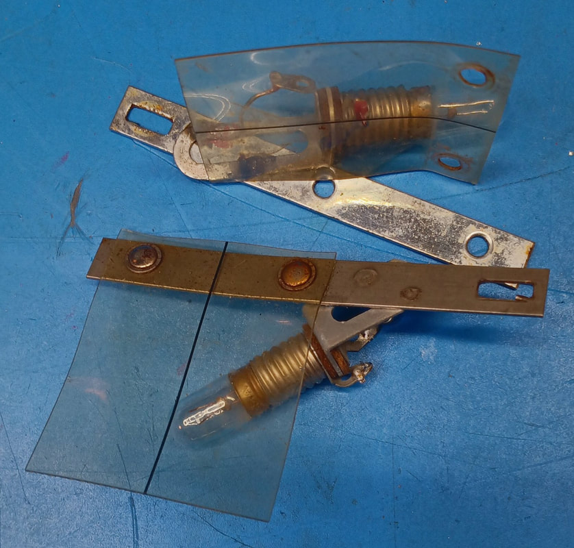
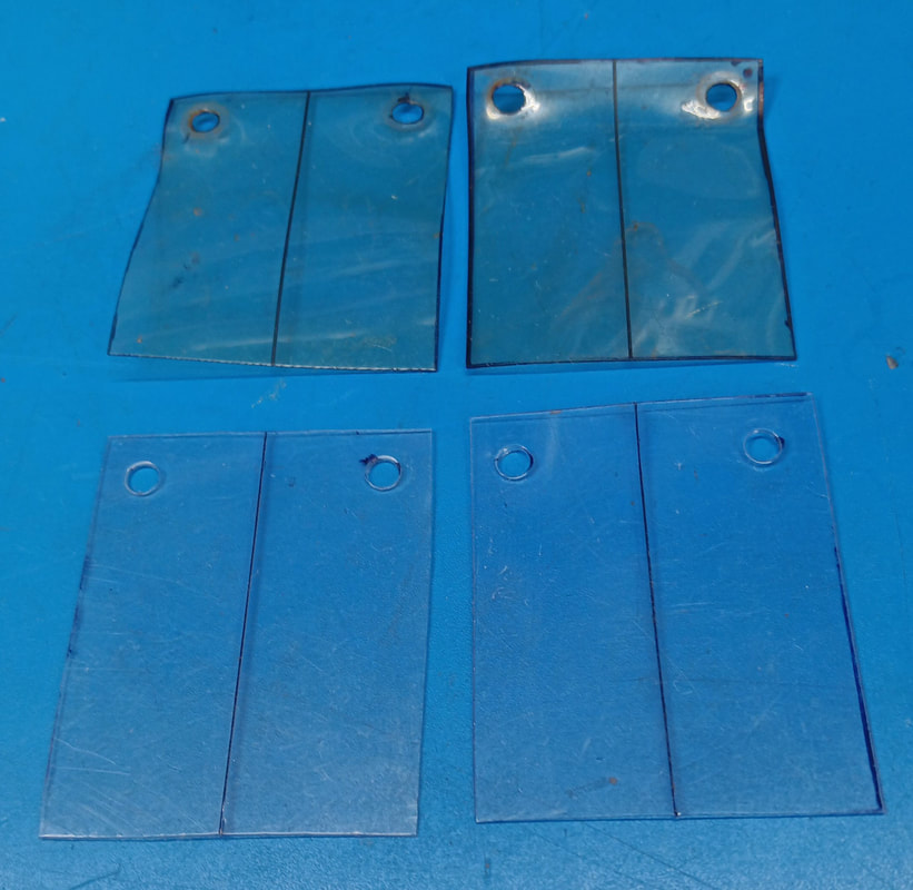
The dial hairlines are warped, same as the ones on the 561. I'll make a new set so the dials don't get scratched up rubbing on these old ones.
|
|
The new plastic hairlines were cut from salvaged heavy plastic packaging. The center hairline was cut with an exacto knife and filled with black paint. When cutting these lines the very tip end of the cutting blade is broken off so that a thicker line can be cut without cutting too deeply.
|
|
The top of the chassis is finished. Everything has been cleaned and all the tubes were given a quick check on my EMC model 200 tube tester. I also installed the new hairlines I made.
I ran into a small issue with the Audio Zero trimmer capacitor. It is a bit different physically from the one in the model 561 and when its connection terminals face the tuning cap as it was originally mounted, the audio frequency dial rubs on it. To fix this I rotated it 180°, but I had to run longer connecting leads since the terminals now face away from the tuning capacitor. |
|
Under the chassis I also finished replacing all the bad and out of tolerance parts, so it's ready to be powered up, tested and calibrated.
|
|
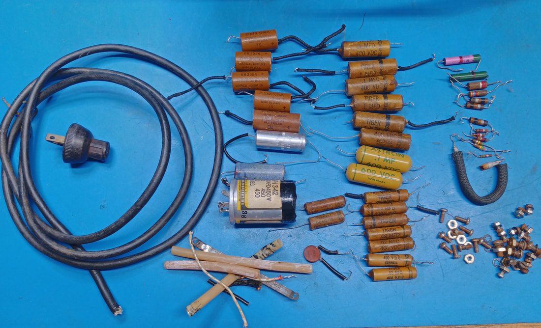
A summary of parts replaced includes
17 resistors, 26 capacitors and the 2 dial hairlines. All rusty screws, washers and nuts have been changed out, a new shielded power cord installed, and a fuse has been added along with a polarized power plug. One of the two yellow plastic encapsulated Astron capacitors checked very good on the Heathkit capacitor tester, but the second one shows a small amount of leakage, so I replaced both just to be safe. |
|
The front panel is finished, too. I just need to align the dials during calibration. This generator didn't come with any cables, but I have the two from the 561 for testing. The audio dial alignment mark should be set approximately 1/4" to the right of its hairline according to the alignment instructions.
I also have two new old stock plugs to make test cables for this generator, but I don't have the back shells, so I'll probably have to make those if I can't locate any. Apparently these connectors are the same as vintage Ford automotive speaker plugs. |
|
|
The alignment procedure for model 561 also works with the 666, and the RF alignment just needed the band ends tweaked. I was surprised how close the original band alignments were even after replacing all the bad components, removing and reinstalling the dials, and replacing all the rusty lock nuts on the band coils. I did have to adjust C-50 to give the trimmer for the top of Band E enough adjustment range. And the main RF tuning capacitor was a bit intermittent when fully meshed, causing the oscillator to drop out mostly on the low end of Band E, but cleaning and lubing its pivots fixed it.
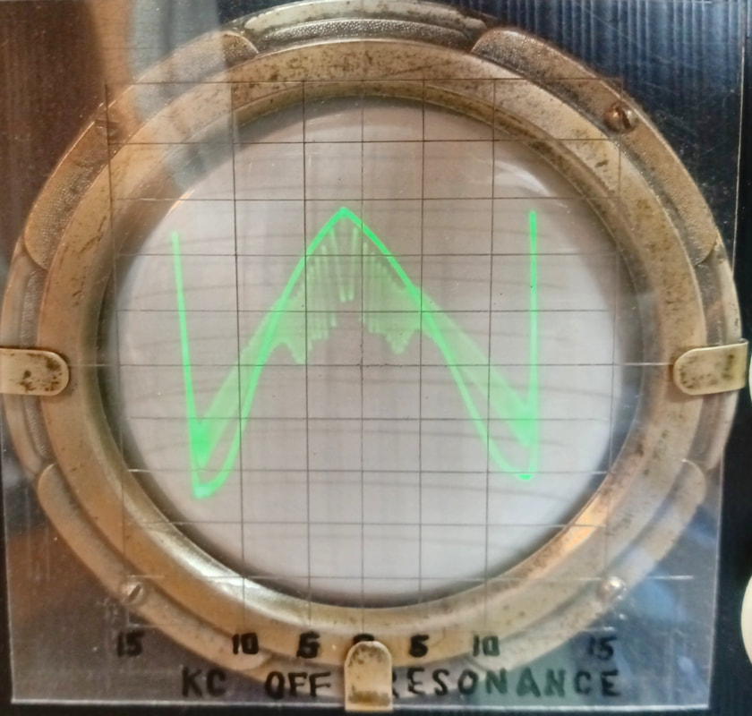
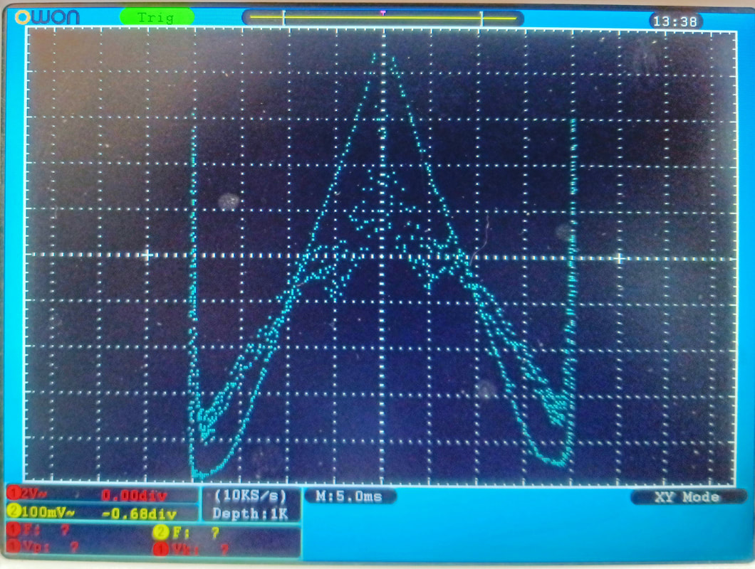
The photos are from the frequency modulator alignment. On the left is the curve displayed on the model 560-A Vedolyzer and on the right is the same curve as rendered on a digital oscilloscope.
The adjustment trimmer (R55) for the percent of modulation had been replaced with two 100Ω resistors in series, but I reinstalled a 1KΩ pot and then calibrated it.
I set up the RF generator to 200KC on Band A and adjusted the Carrier Level control to 100,000 microvolts RMS out using a digital oscilloscope. Then R34 in the RF Voltmeter circuit was adjusted to calibrate the Carrier Level mark on the meter.
The AF alignment is just setting the fixed oscillator to 209.5KC and then zeroing the variable oscillator to it at the zero mark on the dial, and with the "Zero Audio" trimmer capacitor set at half capacity. The dial alignment is not super accurate but is just fine for radio repairs. I have three of these Supreme BFO audio oscillators and none of them reads very accurately on the AF dial.
|
Starting to reassemble the generator by reinstalling the bottom plate. This is the first piece of Supreme gear I've owned that has a cover plate on the chassis. I suppose by around 1950 they were getting just a little more safety conscious.
The screws to mount the bottom plate and secure the generator in the cabinet are all Philips head, which I think could be original since by around 1950 they would have been more commonly available. But all the front panel assembly screws are still fillester head same as on their older equipment. |
|
|
|
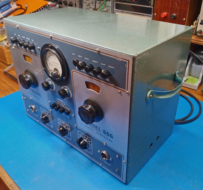
It's back in its cabinet and ready to go. I'm not sure what I'll do with this generator since I already have a model 561 on my workbench. For now I guess it will go on a display shelf beside my extra model 560 Vedolyzer and model 562 Audolyzer, the two instruments it was meant to be paired with.
Page created 6/1/2023
Last updated 7/8/2023
Last updated 7/8/2023
