
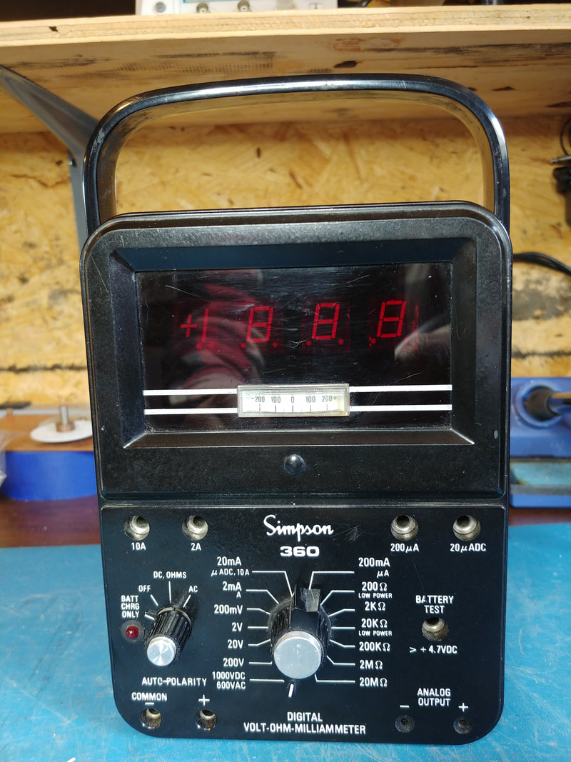
Simpson Model 360-2 Digital Multimeter
This meter is a good example of why I now try not to buy vintage electronics from a certain online auction site. Advertised as being "collector quality", outside it was in decent shape but inside it was a trashed rat's nest. Some hack had miswired or disconnected the wiring to the internal fuses, the external power connector and the batteries, and had completely destroyed the delicate analog meter movement. No wonder the seller made sure to say he had "forgotten" to take any pictures of the inside of the unit.
The meter is from the mid 1970's and is kind of a digitized version of the venerable Simpson 260. I like that it is auto polarity, and for resistance measurements has a low power 200 ohm range and also a 20 Megohm range. The small analog meter would have been useful for checking capacitor leakage or peaking up alignments, things a digital readout fails miserably at.
The meter is from the mid 1970's and is kind of a digitized version of the venerable Simpson 260. I like that it is auto polarity, and for resistance measurements has a low power 200 ohm range and also a 20 Megohm range. The small analog meter would have been useful for checking capacitor leakage or peaking up alignments, things a digital readout fails miserably at.
|
The 360 is powered by 4 NiCd C-cells or the wall wart charger, if connected. It can also run off 4 Alkaline C-cells, but the wall wart should be disconnected so it doesn't attempt to charge them.
The case is in pretty good shape other than some scratches on the face and the trim of both knobs. But it's not "collector quality", unless your standards are a bit low. |
|
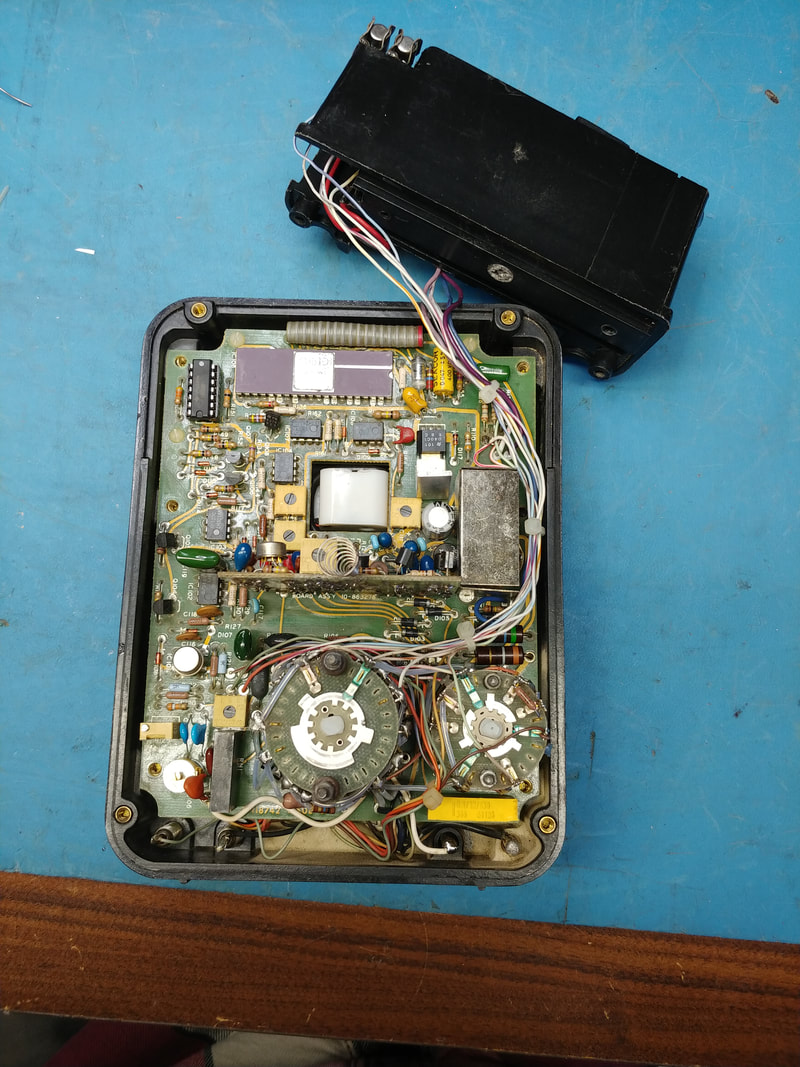
Internally, some of the battery contacts were ruined by leaky batteries, and the wiring to the battery compartment was completely miswired. New battery contacts were made from sheet brass to replace the contacts that couldn't be cleaned. I found a schematic online and sorted all the wiring to the batteries, charger connector and the two fuses for the low ohms and low current scales. Plus there were numerous wires broken off at the PCB from being flexed too much and several capacitors with broken leads or corrosion that needed replaced.
When first powered up the meter would zero but trying to measure anything caused it to immediately go over range. This was traced to an LM2901 quad comparator with three bad sections. It's in the upper left corner of the PCB in the IC socket. There was just enough clearance to add a socket while replacing the IC. |
|
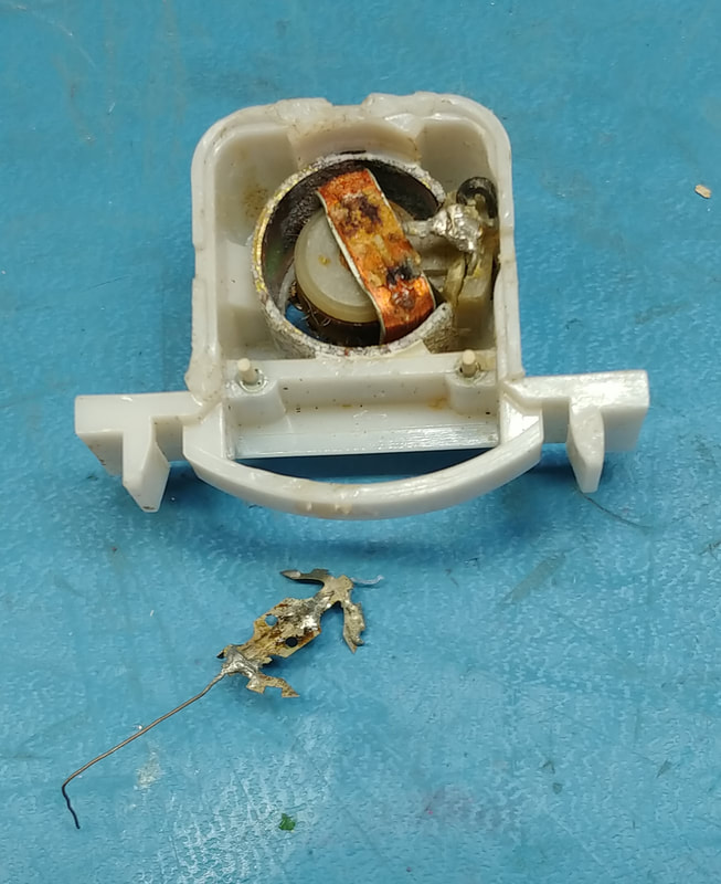
After finishing up with a good cleaning and an initial calibration it's all working except the small analog meter. That was totally destroyed internally and is unobtanium now days.
|
|
Here's the guts of the destroyed meter movement. It's looks like it was made specifically for the 360-2, so not much chance of finding another one just laying around. But who knows, maybe someday I'll stumble across some kind of an edge meter that will fit the panel opening.
|
|
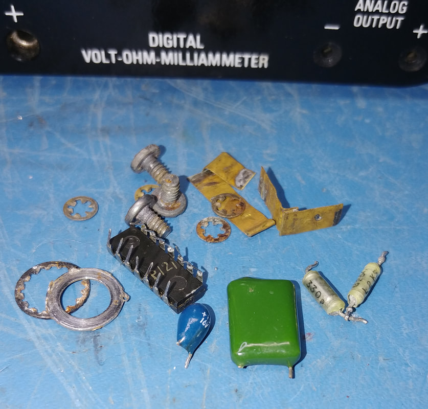
Here's the parts replaced which includes corroded capacitors, caps with broken leads, and the bad LM2901.
|
|
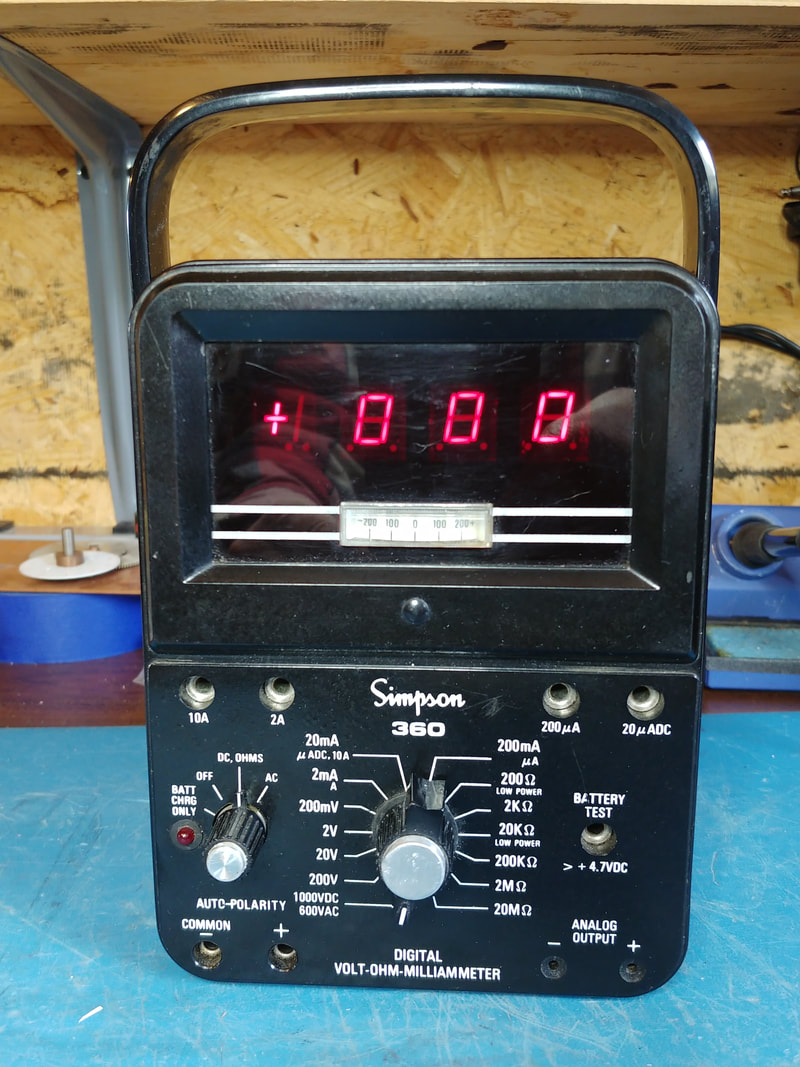
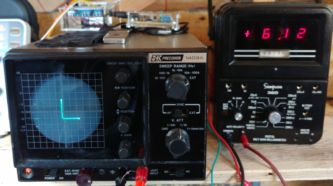
After calibrating the meter it is very accurate across all ranges. In this photo it is connected to my signature tracer's meter output and is measuring the breakdown voltage of a zener diode.
|
Page Created 2/22/2020
Last Updated 4/18/2021
Last Updated 4/18/2021
