
Restoring a knight-kit Spanmaster II Shortwave Receiver
The Span Master II was a short-lived follow on to the original Knight Spanmaster radio kit sold in the 1950's and '60's. The kit was made in Japan and is a 5-tube Superhet with a regenerative IF circuit for a BFO, and covers the broadcast and shortwave bands from 550KHz to 30MHz. The circuit is basically an AA5 design, but with the addition of the extra band coils, and a power transformer so the kids building it couldn't electrocute themselves on a hot chassis in an all-metal cabinet. It kind of reminds me of the 1940's Echophone EC-1 in a lot of ways, except the EC-1 had an extra tube for the BFO, and its transformerless chassis had to be isolated with rubber grommets from its metal case.
This was my very first shortwave radio and the first kit I ever assembled. My mom helped me buy it back in 1969 when I was about 13 years old. I listened to it, and tinkered with it, for years but eventually gave it to a nephew, which was the last I ever saw of it. I had been looking for another one for several years before finally coming across this one in pretty decent condition. It's been sitting patiently on my shelf waiting for me to find time to slow down enough to enjoy restoring it, and reminisce just a little on my younger days...
This was my very first shortwave radio and the first kit I ever assembled. My mom helped me buy it back in 1969 when I was about 13 years old. I listened to it, and tinkered with it, for years but eventually gave it to a nephew, which was the last I ever saw of it. I had been looking for another one for several years before finally coming across this one in pretty decent condition. It's been sitting patiently on my shelf waiting for me to find time to slow down enough to enjoy restoring it, and reminisce just a little on my younger days...

|
An Allied Radio catalog ad from the Spring of 1969 for the "New knight-kit Spanmaster II". This is the earliest ad I could find. In the 1968 catalog Allied was still advertising the original Spanmaster. The Allied Summer 1969 and Christmas 1969 catalogs advertised the Spanmaster II at $10.00 off, but by 1970 it was back to $29.95. I did not see it in the 1971 catalog so it appears to have only been available for two years. I suppose by 1971 tube radios were on the way out, plus Allied Radio, which owned knight-kit, was bought by Radio Shack (Tandy) in '70, so that might have had something to do with it, too.
|
|
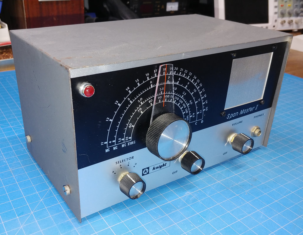
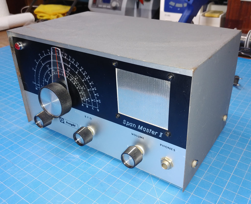
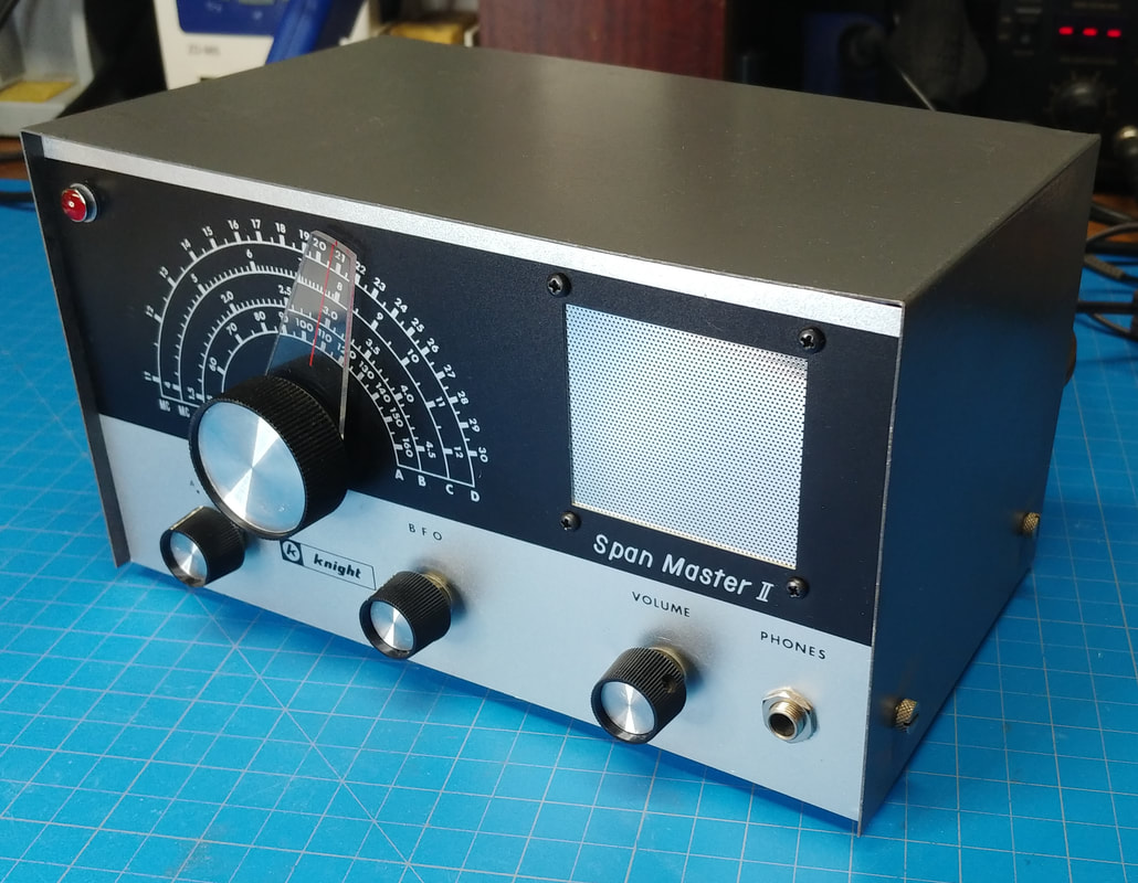
The cabinet and front panel are in good shape overall, with just a minor scuff or two on the panel, but the cabinet top has multiple paint chips and scratches and I plan to refresh the paint on it. One small knob has a chip out of it but I think I have an original knob to replace it.
This little set's performance may not be anything to write home about compared to a real communications receiver, but as a kid it was all I could afford, and with a long wire antenna I strung up, it pulled in shortwave stations from around the world. Scanning through the bands was fascinating to this 13-year old, and I dreamed of exploring the world. And I actually did see my share of it later in life, so just maybe this little radio planted a seed. |
|
Before tearing it down I hooked up an antenna to see what it would do. The switches and pots are so dirty they had to be worked back and forth in order to get the radio to play at all. I think the broadcast band has been screwdrivered, it's way off. But band C was very close. I tuned in WWV on 10MHz right at the mark. The other two bands were pretty dead so I hooked up a signal generator and they are off too.
|
|
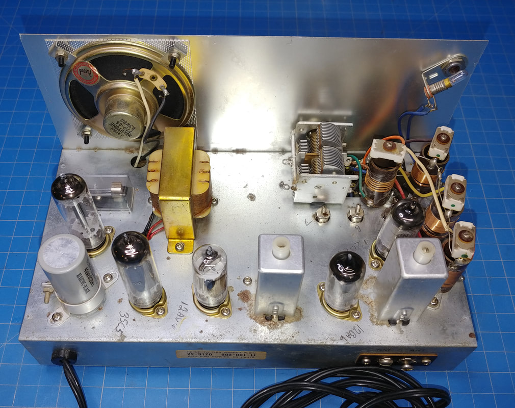
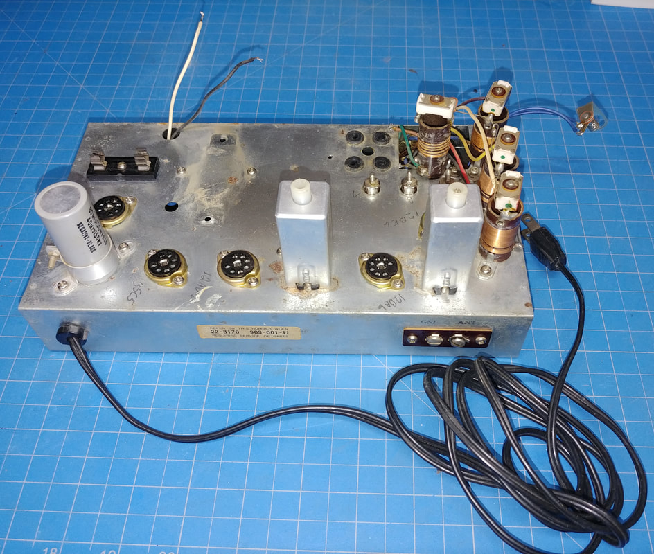
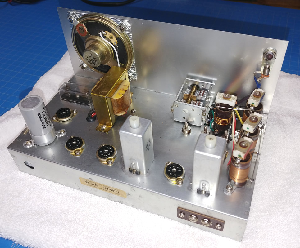
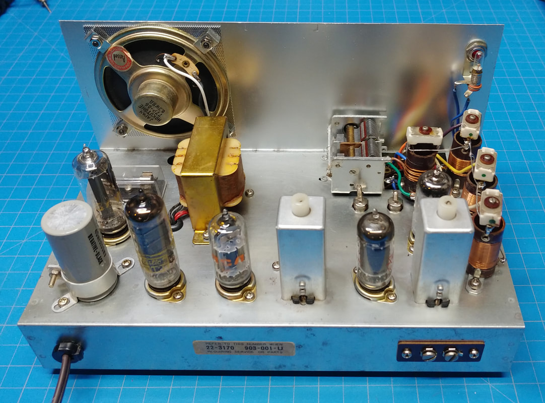
The tube line up from right to left is a 12BE6 convertor, a 12BA6 IF, a 12AV6 detector and first audio amp, and a 35C5 audio output, all powered by a 35W4 rectifier. There is no RF amplifier in the set.
The filaments of these tubes are a series string across the AC line, but only add up to 107.8VAC (with a maximum ÷/- 10% deviation). The mains voltage in Japan is 100VAC so this is fine there, but my mains voltage varies between 122 and 125VAC, so I will change the 35C5 audio output tube to a 50C5 to bring the nominal series string voltage up to 122.8VAC. |
|
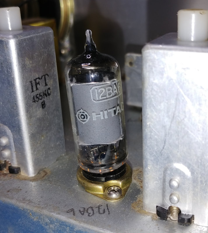
Four of the five tubes are the original Hitachi tubes that came with the kit. Only the 12BE6 convertor tube has been replaced and so far it's the only non-original part I see in the set.
I will remove the Hitachi tubes and keep them boxed with the radio, and for everyday use I'll install another set of tubes. |
|
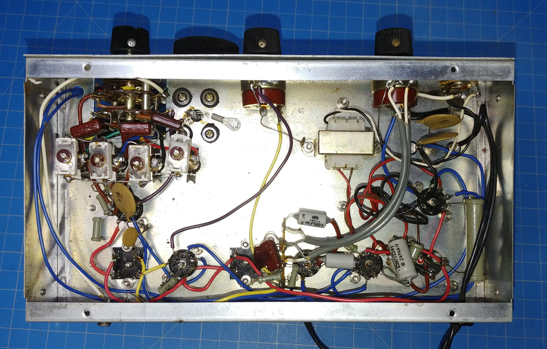
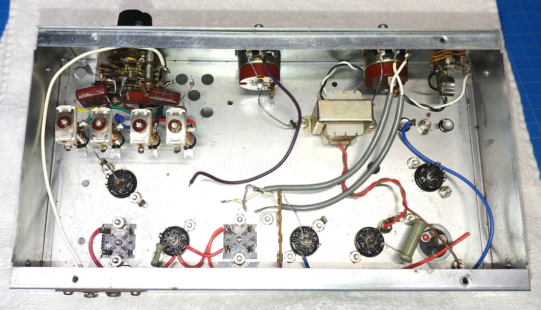
Under the chassis is relatively clean. I need to replace the little oil-filled "Zeus" brand capacitors. They are very leaky. The 40uF and 60uF capacitors, in the electrolytic filter can, actually test very good, so I'm tempted to just leave them in-circuit.
|
|
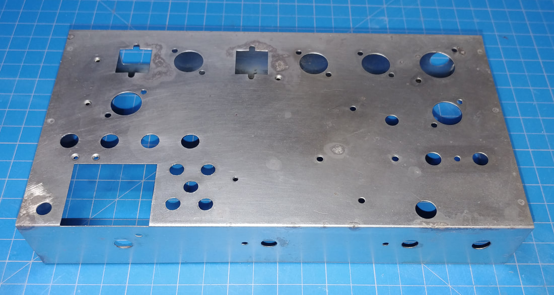
The only thing I'm not happy with is the rust on the chassis, so I've started stripping the chassis down to clean it and then coat it with laquer so it doesn't happen again. There is rust around both IF transformers and in various spots around and under the chassis.
Also, someone was careless with their soldering iron and I see multiple wires with insulation melted and burned in spots, which I will replace. Some of the soldering is good, and some not so much, but overall I guess it's not bad for a kit. I think someone was trying to troubleshoot this set too, because I found some connections that appear to have been pulled loose and resoldered. |
|
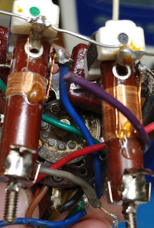
The contacts in the band switch are very dirty and corroded. Sounds like a job for Deoxit. They're completely coated in crud.
|
|
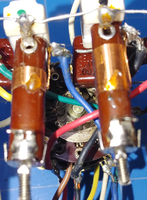
After three days soaking and cleaning the band switch with contact cleaner and Deoxit the contacts are much cleaner. I can't remember the last time I cleaned a switch so crudded up.
|
|
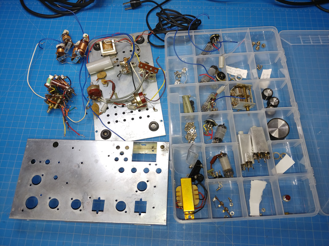
Almost back to kit form again. Of course the chassis wouldn't need to be stripped just to repair it, but since I want to clean and coat the chassis I have to get everything out of the way. I'll also clean any parts needing it, not only was the band switch dirty, but the pots and tuning capacitor also need cleaned.
|
|
This is about as much as I can do to remove the rust without winding up with shiny steel and no zinc plating, which is not what I want. Next I'll give it a coat of clear laquer. I'm not trying to make it perfect, just get rid of the rust that's already there, and stop any further rusting.
|
|
Starting to reassemble the chassis. I'm following the manual, more or less, to rebuild it, although there's a few wires and components that just didn't need to be taken apart to get them out.
|
|
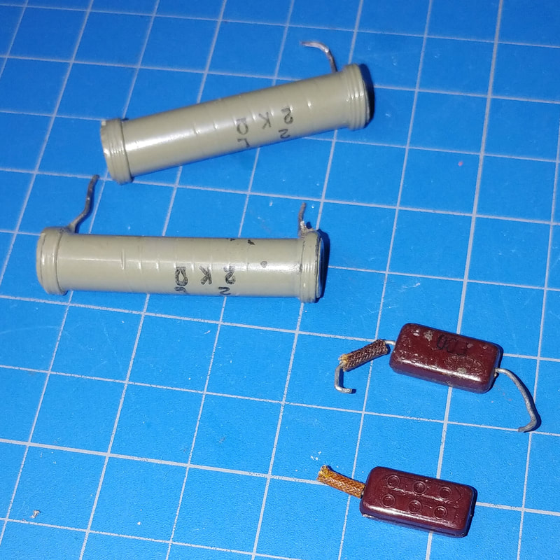
The strangest things happen sometimes. As a kid I "experimented" some with my radio, as kids are wont to do, and swapped out a part or two. Fast forward 50 years and while searching for a part for another radio one day, I came across the original 2KΩ power resistor from my first Spanmaster II. I recognized it immediately. Then while dissasembling this radio one lead of its 2KΩ power resistor just fell off. It might have enough of a lead left to repair it if I had to, but I have the resistor from my original radio to replace it, so no problem. Then while rebuilding the chassis a lead broke off of a 500pF mica capacitor. So I was digging through my box of mica caps and guess what I found - the original 500pF cap from that first Spanmaster II. It even still has the spaghetti tubing on it. How weird is that? So I have at least two original parts from my first set, and both are parts I ended up needing to restore this set.
|
|
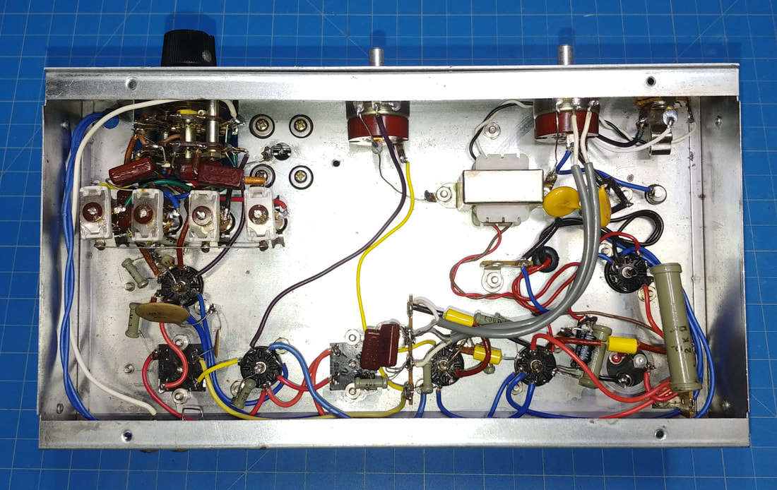
Under the chassis I've started rewiring it and replacing any damaged wiring. All the original components will be reinstalled as long as they test good.
If it wasn't for the style of tube sockets in this set I wouldn't have needed to tear the radio down to so many individual components to get to a bare chassis. These tube sockets have to come out the top of the chassis, whereas the sockets on many radio chassis can be removed through the bottom, and much of the wiring and components can be left connected. But that's OK because I'm really enjoying following along with the construction manual as I rebuild it myself. |
|
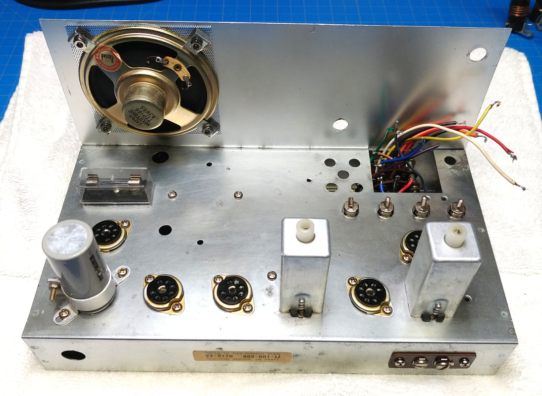
The top of the chassis is finished. Everything on top is original except I had to replace the nylon screws for mounting the speaker and grill because the heads had been almost twisted off of two of them. I replaced all four with black oxide screws. And the four grommets under the tuning cap were deteriorating and replaced. I also added a rubber grommet to the hole for the transformer's wires.
Under the chassis I still need to complete the final wiring page in the manual. |
|
The bottom chassis wiring is now complete with the exception of the power cord. It doesn't have a polarized plug, but rather than cut off the plug I'll replace the whole cord and put the original cord in the box with the tubes and other original parts I've removed from the radio. That way if I would ever want to return the radio to 100% original condition, the parts will be there.
The only bad components replaced were the three Zues oil-filled 0.005uF capacitors. Two good ceramic disc caps were also replaced for reasons mentioned below. |
I changed the AC wiring in the set to make it a little safer. The power switch and fuse are now wired in series and connected to the line-side of the polarized plug. I also replaced the two ceramic capacitors from the AC input to ground with ceramic X1Y2 safety capacitors.
The final change I made was to the power supply filter capacitor C-18. Even though both caps in it test good they will eventually need to be replaced so I added a terminal strip and connected all the wiring for C-18 to it and jumpered C-18 to the new terminals. All that needs done when I replace the filters is pull the jumpers and wire the replacement caps to the terminal strip.
All these changes are non-destructive so the radio can be returned to original if desired. But to make it safe and functional, some minor changes were necessary.
|
I picked out some good tubes from one of my drawers of loose tubes and powered the radio up on my variac to make sure there were no surprises lurking under the chassis. Then I did an alignment per the manual.
As I suspected, someone had misadjusted band A, the broadcast band. In the alignment procedures there are one or two asterisks next to the oscillator frequencies, denoting whether the coils and trimmer caps are tuned to the lower or upper peak of the generator signal. Band A was tuned to the wrong one. Band B was also way off as was band D. But on band C the alignment points were very close, but I still need to check if they are adjusted to the correct peak of the generator. And the IF alignment was still fairly close too, so it only needed minor adjustment. In the end I did spend considerable time tweaking the band alignments, including band C, to be sure each band end is on the correct peak. If not, everything in between is mucked up. The most notable issues were the tracking on band C is a little off even though the alignment points are good, and signals on band D are noticeably lower than the other bands. But as I recall, my first Spanmaster II was a bit deaf on band D also. |
|
My local AM broadcast station (yes, where I live there's only one) sounds pretty good and even better with a larger external speaker plugged in. It sounds better on AM than my Radio Shack DX-160. Likewise with shortwave broadcast stations, but the lack of bandspread tuning and a wide IF makes it very difficult to tune in narrow CW or SSB stations. However I did find some amateur AM stations down on 80 meters that were very clear and easy to copy. Regardless of Allied's advertising claims, don't expect too much from the amateur bands with this receiver, but for shortwave listening and AM DX this little set does surprisingly well for a kid's first kit, and I'll be having a lot of fun with it, again.
|
Page created 12/5/2020
Last edited 1/17/2021
Last edited 1/17/2021
