Restoring a VOMAX 900 VTVM
|
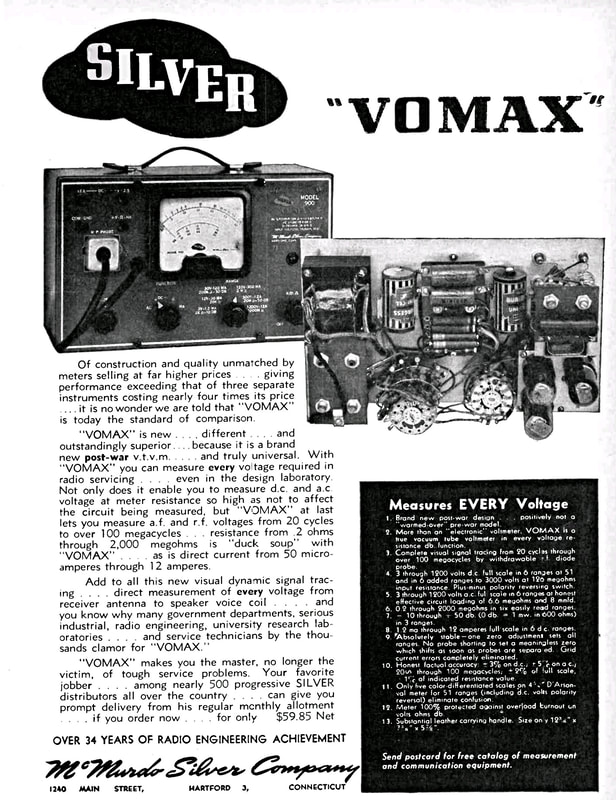
McMurdo Silver called the VOMAX a universal VTVM capable of measuring every voltage in a radio. One important feature that sets it apart from the average VTVM is the very high input impedances that allow the meter to remain virtually invisible to a circuit while making measurements. And it can measure AF and RF voltages from 20 cycles to over 100 Megacycles.
Another really nice feature is only needing to set the meter zero once for all ranges and functions. Even adjusting the ohm ranges to full scale doesn't affect zero. The meter uses four tubes, a 5Y3 power rectifier, a 6AL5 dual diode for rectifying AC signals, and two 6SN7 dual triodes (the 6SN7 is basically two 6J5 tubes in a single envelope) that are the heart of the meter circuitry. A magazine article by McMurdo Silver titled "Universal Test Instrument", explaining the features and circuit design of the VOMAX, can be found in the February 1946 edition of Radio News, which is available online. There is also a two-part article on the VOMAX in Service magazine. The first, entitled "Post War VTVM" is in the December 1946 issue, and the second "Operating the VOMAX" is from January 1947, both are also available online. |
|
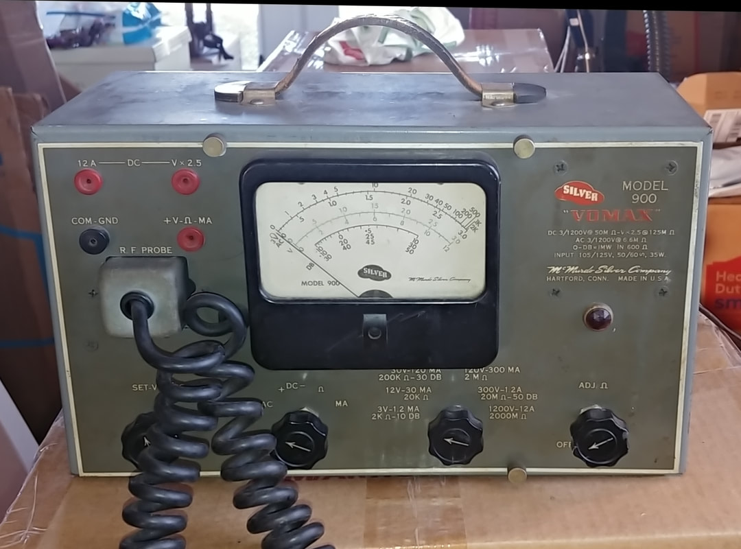
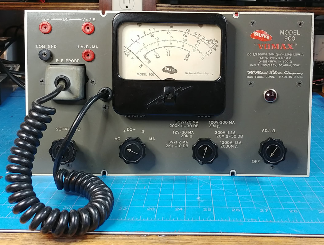
This VOMAX has a different Bakelite meter face than the one illustrated above, and is a later production instrument. I think it's circa 1948 and might even have been produced after McMurdo Silver's death that same year because I found another instruction manual online, with a cover photo that matches this unit, stating the McMurdo Silver Company is a Division of General Radionics of Toronto, which would have been after his death.
The schematic in the General Radionics manual is slightly different from the original schematic, with changes to the ohmmeter circuit and power supply filters. |
My meter matches the original schematic as far as the power supply goes, but matches the later one for the ohmmeter, so I can't really be certain when the meter design changed.
Other differences are the component mounting screws in the front panel are phillip's head, whereas on the meter in the ad the screws are slotted. And the RF probe cable is coiled, not straight like in the ad.
Overall, this instrument is in good physical condition, the paint is decent and it looks to be complete. But one word of caution on cleaning the front panel. Be careful with the red paint on the logo and name. After 65 plus years it is delicate and even water will wipe it off.
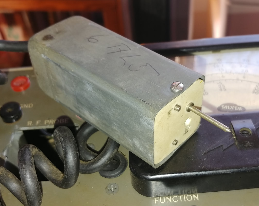
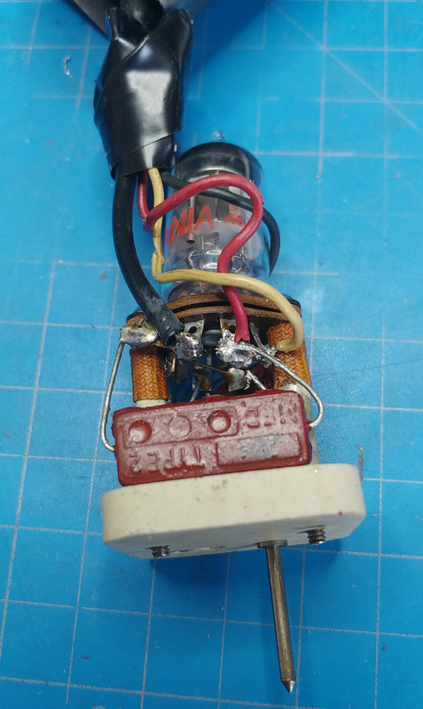
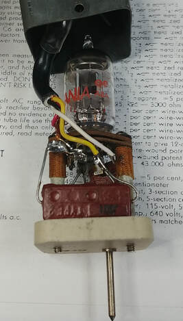
In the first probe picture someone tried to repair it, but just made things worse. The soldering is very poor, with cold joints and at least one lead that wasn't soldered. And there was a solder glob on the spacer between pins 3 and 4 that could have easily shorted out the filaments.
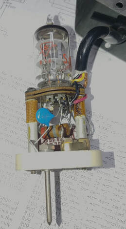
Another issue with the probe is the rubber coated wires in the coiled cable. The rubber on the outside of the cable is still pliable but the insulation on the individual wires is dried out and crumbling. Just touching a wire causes more crusty rubber to fall off. I tried to repair it, but the best solution is a new cable, if I can find one.
In the second picture a trip to a local electronics shop solved the cable problem. The owner had a box of old microphones with coiled cables and we found a suitable replacement cable on one of them.
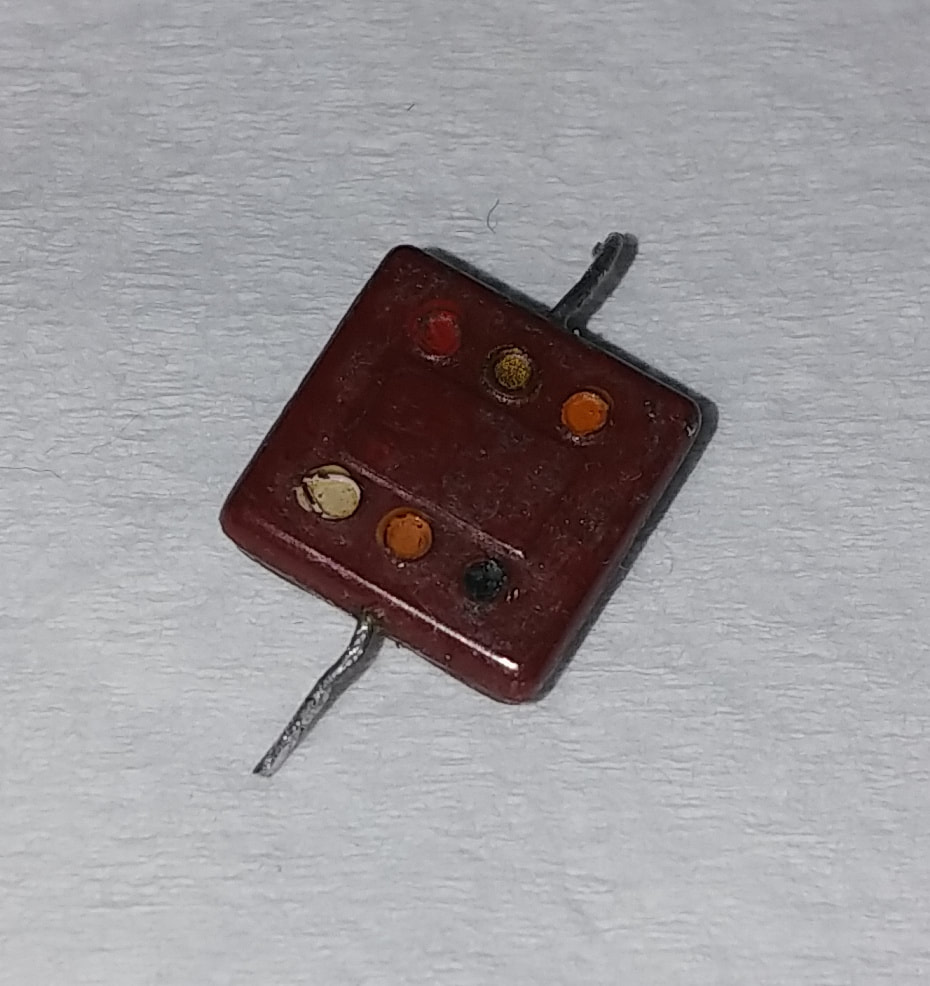
In the third photo the 500pF 500VDC mica capacitor from the probe tip to the 6AL5 shorts out at voltages over 200VDC on my cap tester. I replaced it with a 470pF 3KV ceramic capacitor.
I'm not sure why they would specify a 3KV capacitor inline with the 6AL5 when the probe is socketed, and then only use a 500V capacitor to the probe tip when it's used directly, unless maybe it was incorrectly replaced at some point in the past.
I'd bet the bad 500pF cap is due to someone touching the probe tip to a circuit where the DC voltage exceeded the cap's voltage rating.
|
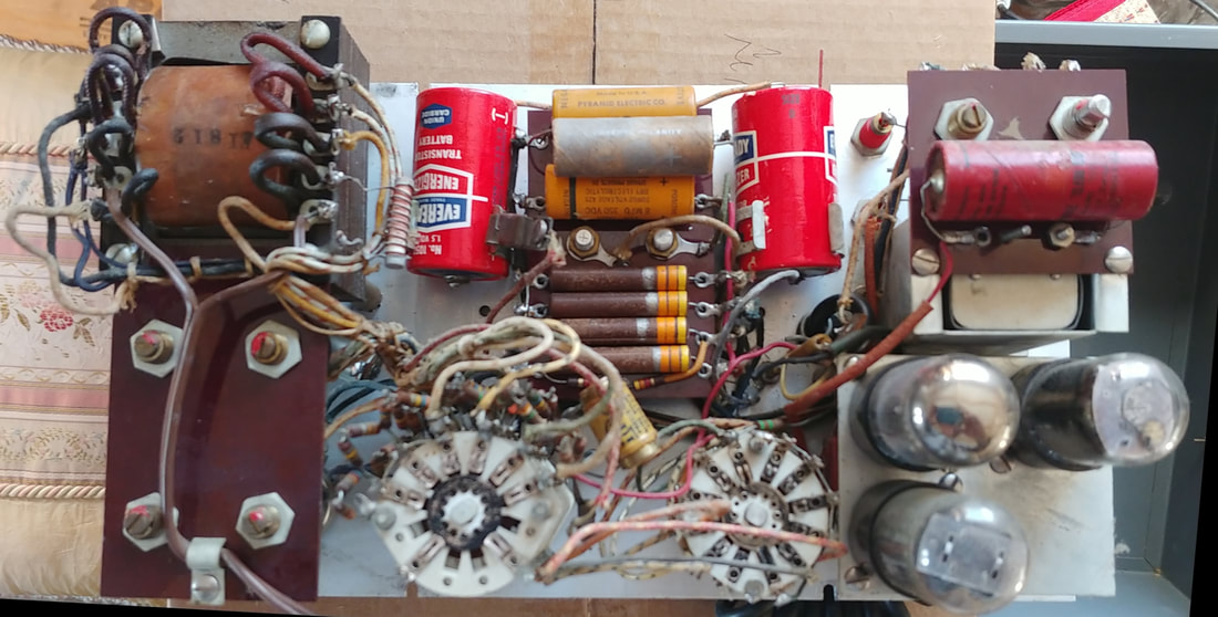
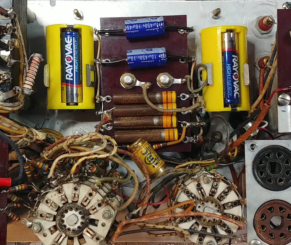
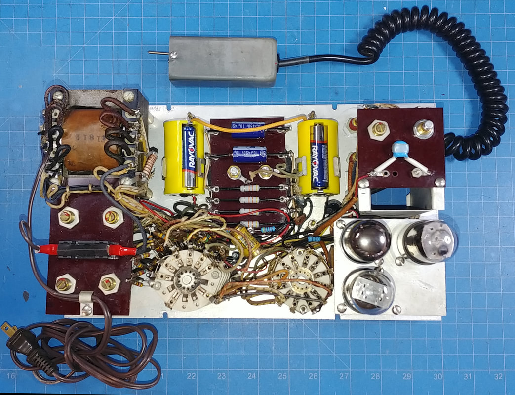
Inside the meter is clean. Even the old circa 1960's Eveready batteries haven't leaked on anything yet. Someone has paralleled another filter capacitor across one of the old filter capacitors on the phenolic board. The two "original" caps are not identical, so it's possible it was serviced a long time ago, even before someone tacked in the extra cap.
|
I see that R42, a 10MΩ calibration pot has been changed, but the replacement is only 2MΩ. It's poorly soldered and looks like an old radio volume control. It was replaced with a new 10MΩ pot.
I also noticed a 5.1MΩ resistor soldered from a lug on R42 to ground, that's not on the schematic. The soldering is so poor the resistor isn't really soldered to the lug.
In the manual, the maintenance section has instructions on how to troubleshoot the meter if zero for AC and DC doesn't coincide. It mentions things like reversing the wiring on pins 2 and 7 of the 6AL5 in the probe, adding a 5.1MΩ resistor from the outside wired lug of R42 to ground, and replacing the 6AL5.
The 6AL5 looks like new, no dirt or scratched lettering, and both diodes read very strong, which makes me think this actually is a new tube. And the sloppy soldering on the probe pins and the 5.1MΩ resistor added to R42 sure looks like someone was trying the troubleshooting suggestions in the manual. They even went so far as replacing R42. It all points to a problem zeroing and making measurements.
|
One definite problem in the meter is mica capacitor C4, that goes from ground to the grid of one triode in the first 6SN7, which is the input line coming from the function switch. On an ohmmeter it doesn't show any signs of leakage and looks fine. Mica capacitors are generally very reliable, so whoever attempted to repair this might have assumed it was good, but when checked with my IT-28 capacitor tester it shorts with just a few volts across it. Just shows once again that an ohmmeter doesn't cut it for testing capacitors. And an intermittently shorted capacitor across the input grid would certainly cause issues.
The capacitor is listed as 5000pF on the schematic, but this cap is only 3900pF, and from its markings looks to be military surplus. I replaced it with a 4700pF ceramic cap. |
|
I don't want to be soldering and unsoldering ohmmeter batteries, but there's not much room to add "D" cell holders on either side of the meter movement in place of the existing clips. So I ordered a couple of AA to D cell adapters that use 3 AA cells in parallel in a round "D" sized battery holder.
I can solder to the adapters, snap them into the existing "D" clips, and still be able to easily change out old batteries without unsoldering anything. I may even print sleeves from a graphic of an old battery label, to slip over the adapters and make them look a little more authentic. Soldering to the adapters turned out to be more difficult than expected. Not sure what the metal is that's used for the contacts, but silver solder finally did the trick. |
In a parts drawer I also found a small 2-pin connector pair with pigtal leads that I added so I can even unplug the batteries.
|
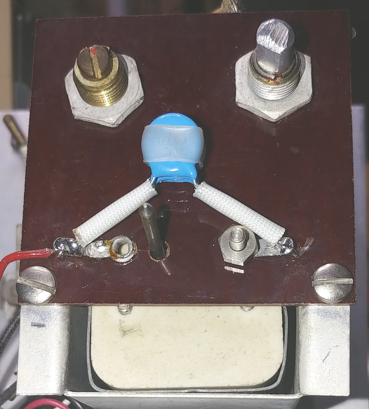
There is a 0.03uFd 3000VDC blocking capacitor shown on the schematic for the AC input to the 6AL5 when the probe is inserted into its socket on the meter, but in this unit it is only a 2000VDC cap. It's an old oil filled paper cap, but I can't tell if it's factory or not, and my capacitor checker only tests to 600VDC, so I'm just going to replace it. I made a new cap by paralleling three 0.01uFd 3KV ceramic caps.
|
|
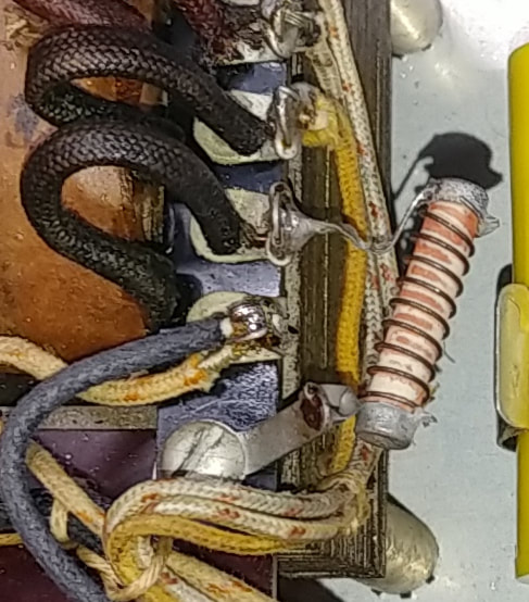
There is one other resistor in the VOMAX, shown in the photo, that is not on the schematic. It is a 0.91Ω 1.5-watt wirewound resistor from one side of the 6.3-volt transformer filament winding to ground. According to a two page letter to customers (separate from the manual) it was added after S/N 6000 to lower the voltage to the tube filaments. This VOMAX is S/N 13030 so it's already there, but in earlier units it should be added.
|
|
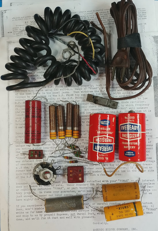
So far I have removed an extra capacitor and resistor, and replaced 5 capacitors, 9 resistors, the coiled cord to the probe, the power cord, a 10MΩ potentiometer, a broken terminal strip (for connections to the coil cord), and also added another terminal strip (for a battery connection), an AC line fuse and fuse holder, and 2 "D" cell battery adapters.
The range resistors have not been replaced yet. I'll do those after I get the meter powered up. The manual says they are "1% matched pairs aged for stability", so I'll have to match up some new pairs. |
|
The meter is finally ready for power up and testing. It now has a polarized line cord and a fuse in line between the cord and power switch. All the tubes checked OK on the drugstore tester, but the real test is how they do in operation. All the switch contacts and controls were cleaned with Deoxit. So the question now is, will it zero?
|
|
The front panel and all the Bakelite has been cleaned and polished while being very careful around the red painted logo.
The meter uses pin jacks for the test leads, but the V-Ω-mA jack is a bit worn, so I'm going to swap it with the 12A jack. And I'll make a test probe for the meter similar to the original. |
The initial power up went well. The meter zeroed on DC and ohms and so far all functions seem to be working except AC zero, which I'll come to in a moment. After letting the meter warm up I noticed zero was still drifting a little. The manual says this can be caused by heater to cathode leakage in the 6SN7 tubes.
The tubes checked OK, but with the exception of the 6AL5, the other three tested a bit on the marginal side. However, I wanted to try them first before installing any new tubes. The manual advises using only RCA tubes, but doesn't explain why, so it's time to install some new ones.
I dug up a couple of RCA 6SN7 replacements and a new 5Y3. The DC Zero is now rock solid after the initial warm up. I also replaced the 6AL5 with a new RCA tube, but so far I haven't noticed any change in AC operation.
The only problem I still see is AC zero is pegging the meter needle below zero and R42 can't correct it. Adding the 5.1MΩ resistor to R42 does help, but the real culprit is stray AC pickup on the contact potential diode line. The diode is rectifying it which is impressing about -4 volts of half wave pulses on the line. It's easily solved by shunting the stray AC to ground with a 0.047uF capacitor. The cap doesn't affect the contact potential DC component, which is what the circuit is measuring, and the AC ranges zero out nicely using only R42. No added resistor is needed. So far I don't see any down side to adding the capacitor.
|
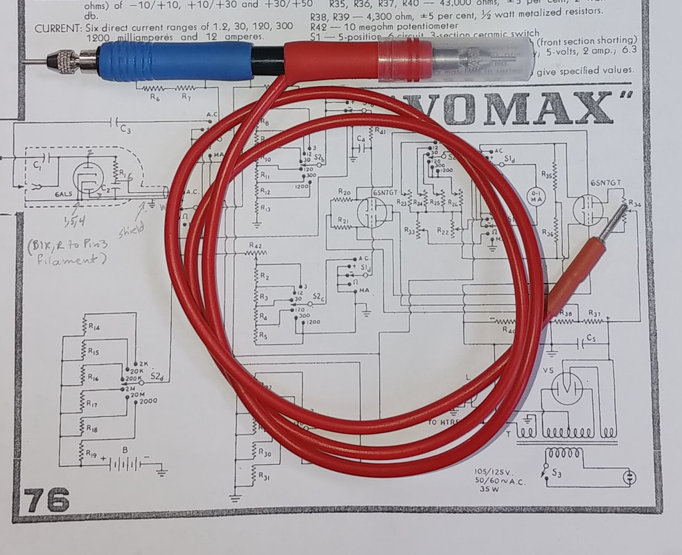
To complete the calibration I need a VOMAX probe. As usual with most of the vintage gear I find, the original probe was missing and I had to make one. It's double-ended, similar to an original. The red end is a direct probe, for ACV, mA, and Ohms, and the blue end has a series 1MΩ 1% resistor for DC volts. In the photo I have the sharp little probe tips reversed in their sockets so I won't "stick" myself until I'm ready to use it. There's also a plastic cap that slips over the tip that's not in use so that I don't touch it and possibly affect readings or get zapped by it.
|
|
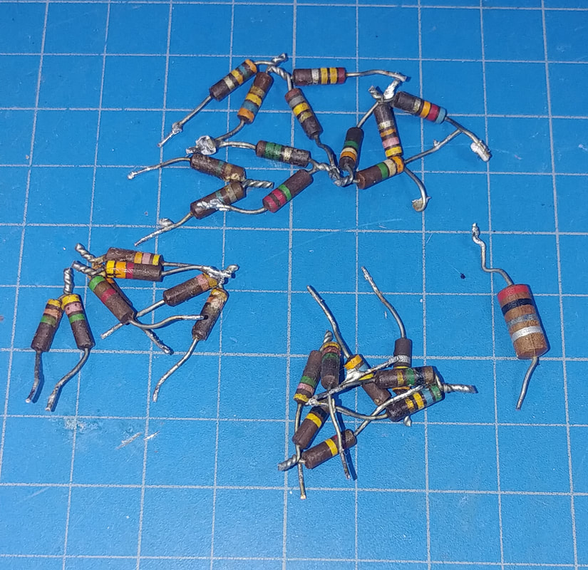
There are 14 pairs of 1% range resistors and all of them were out of tolerance. They were replaced with new resistors hand selected to 1% accuracy.
The first set to go were the four contact potential pairs for the 6AL5 diode. These were done first as part of testing the AC probe and AC zero. The 20MΩ resistor in the photo is also from the AC probe and was out of tolerance as well. The ohmmeter range pairs and voltage range pairs were replaced next. One thing worth noting is that in the original VOMAX circuit the ohms range resistors are wired in parallel from the range switch to the battery, and all but the 10Ω resistor differ in value from the ohms resistors in the later circuit, where they are wired in series with the battery. The mA ranges use precision wirewound resistors, and they are still good. |
|
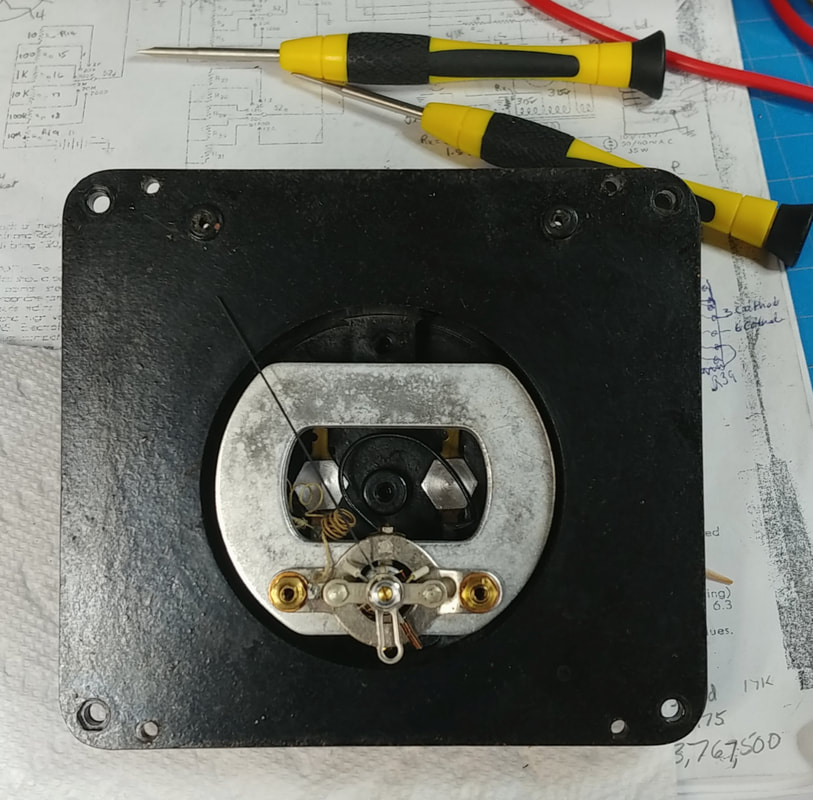
I noticed while testing zero that the meter movement is showing its age. It seems to have friction in the bearings, because tapping on the case causes readings to increase slightly. To be sure the needle is on zero requires a few taps.
Opening a meter movement is not recommended, it's really, really, really easy to damage the delicate movement. It's kind of like working on a pocket watch, but that didn't stop me. Actually I've worked a little with both meters and pocket watches, so I carefully cleaned the pivots and jewels and the inside of the case. It definitely helped the needle swing more freely and I don't have to tap on zero now. |
The range resistors are all within 1% tolerance now, which is more accurate than the meter movement. Because of some non-linearity in the movement, readings are slightly low on the lower end of the ranges, but very close on the upper portion of the scales. Considering the age and condition of the movement, it's probably as good as it's going to get, but it's still plenty accurate for troubleshooting old radios. I'll start searching for a replacement meter movement to see if I can get it back to factory accuracy.
|
The first three AC ranges have separate calibration potentiometers, R23, 24 and 25. The last three ranges use a single common cal pot, R26.
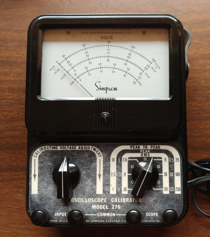
I used a Simpson 276 scope calibrator and a DVM to provide accurate AC voltages for calibrating the AC scales. The ranges calibrated without issue except for the 30-volt range. Its cal pot, R25, is wirewound and the fine nichrome wire is broken in the spot where the wiper contact has sat for decades. Fortunately only the wiper and one end of the pot are connected in circuit, and the brake is closest to the wired end, so I moved the wire to opposite side and was able to calibrate. The AC probe tests OK at 60Hz according to the manual. At low frequencies the probe reads about 30% low because of the reactance of the 500pF input capacitor, but it does confirm its operational. |
|
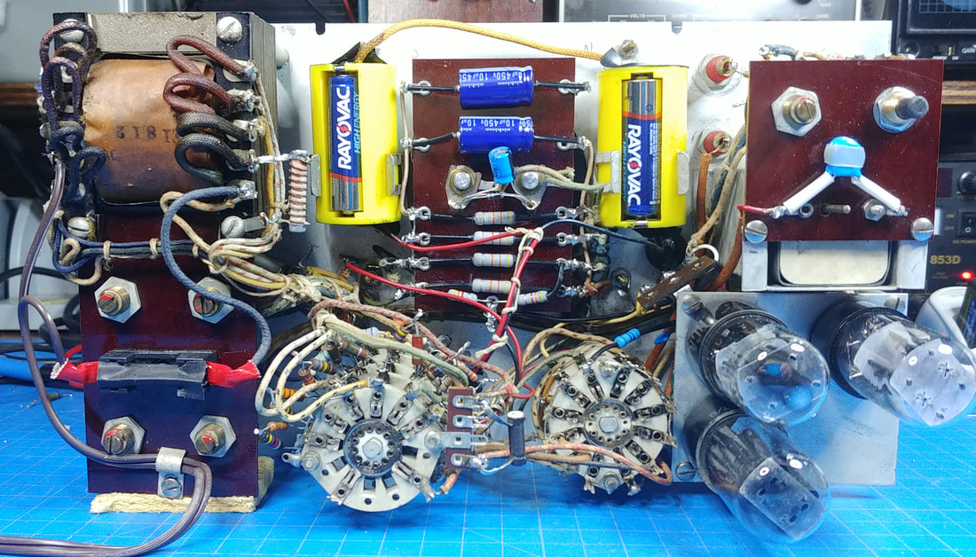
Chassis view of the completed meter. In addition to the new battery holders and AC line fuse, a 100uF damping capacitor and back-to-back diodes were added across the meter movement, and a terminal strip was mounted to the range switch R14.
R14 had one lead soldered to the range switch and the other end soldered to a battery wire that was just hanging in midair. The terminal strip eliminates this flying lead. |
|
It took a while, but I finally found a replacement meter movement. It's the older style but works well. Now the meter is complete and working properly. It was in a lot worse electrical condition than it first appeared, and required more time and effort than I expected, but it will be a useful addition to the radio work bench for high impedance measurements.
|
Page created 11/4/2021
Last edited 6/22/2024
Last edited 6/22/2024

