BC-221-AF Heterodyne Frequency Meter Restoration
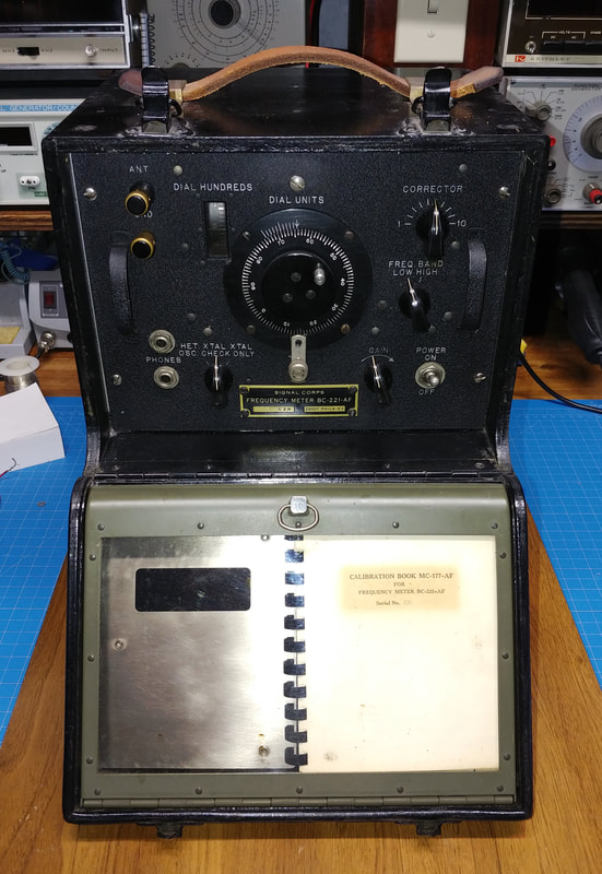
The is a piece I picked up more recently, and is also referred to as an SCR-211-AF. It's a WWII era frequency meter covering 125KHz to 20MHz. There are a lot of different letter designations for a whole variety of BC-221's by different manufacturers. The TM 11-300 technical manual covers them all.
This is actually my third BC-221, the first one went mising the same way as my first LM frequency meter well over 30 years ago. The second one was a really clean unit I picked up at a hamfest about 1991, and gave to my former boss who was a genius RF engineer and an antique radio collector. This newest one is for me.
Frequency meters were used to measure radio frequencies and calibrate radio dials before frequency counters came along and took over the task. But they can still be quite useful even today to verify dial accuracy and frequency settings of receivers, transmitters and signal generators, and even to calibrate frequency counters.
|
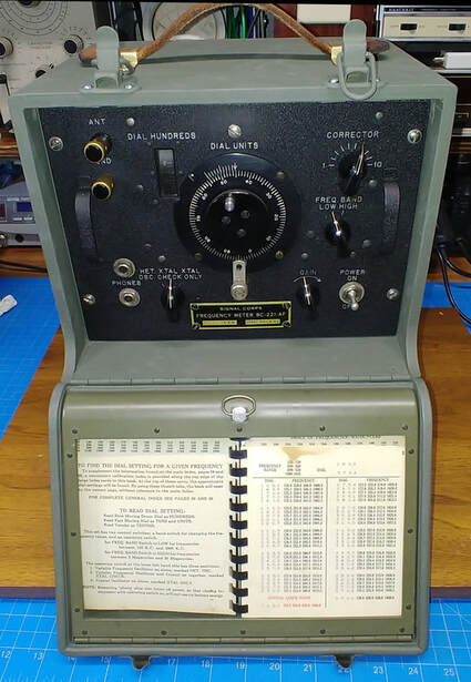
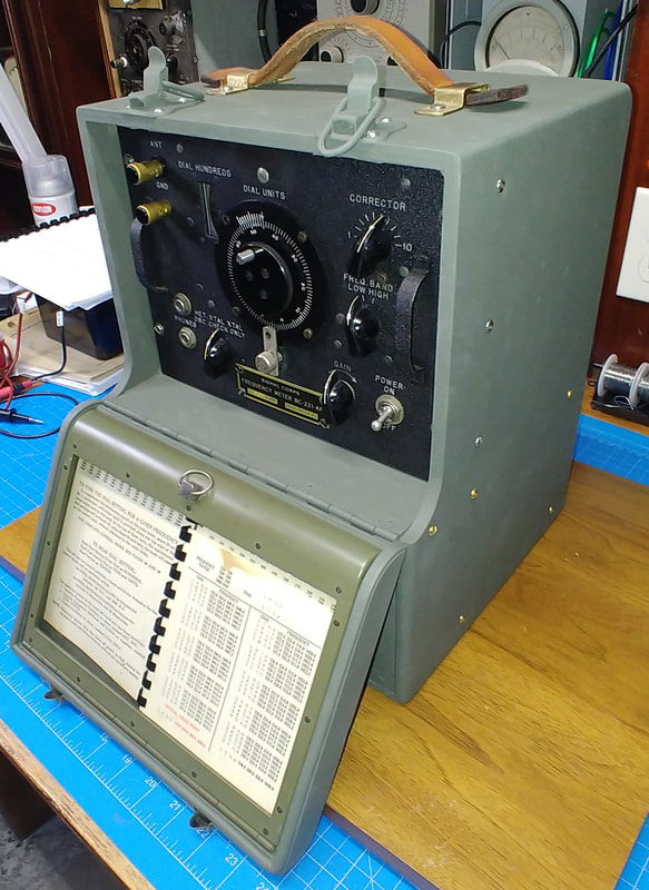
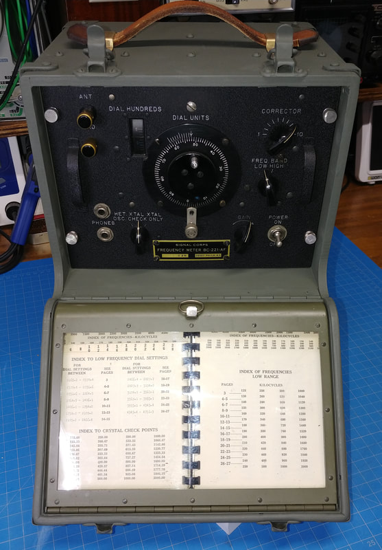
This BC-221 was made by Zenith. The front panel is in nice condition and it has its matching calibration book. The meter and the book are a matched set and serial numbered. Lose the book and your meter makes a nice door stop. It is possible to recreate the book, but the results are supposedly less accurate than the original book.
At first the calibration books were created by hand and it took a person over 16 hours for a single meter. Philco invented an analog computer in the early 1940's that could create the book in about six hours, but the computer needed to be connected to each and every meter to create its book. There is an article on the analog computer and the process of creating the calibration books in the May 1944 edition of Electronics magazine, which is available online. |
|
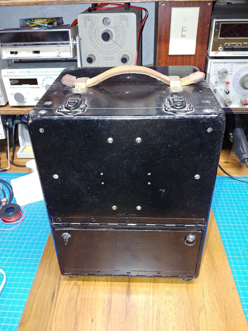
Some BC-221s are housed in aluminum cases and others are cased in wood. This one has the wooden case that was originally olive drab in color, but someone later repainted in black. Only the bottom is still the original olive drab. I will repaint the cabinet to its original color when I get around to disassembling the unit. It is also missing the metal nomenclature tag on the outside so I will copy the tag on the meter's front panel to create a replacement.
|
|
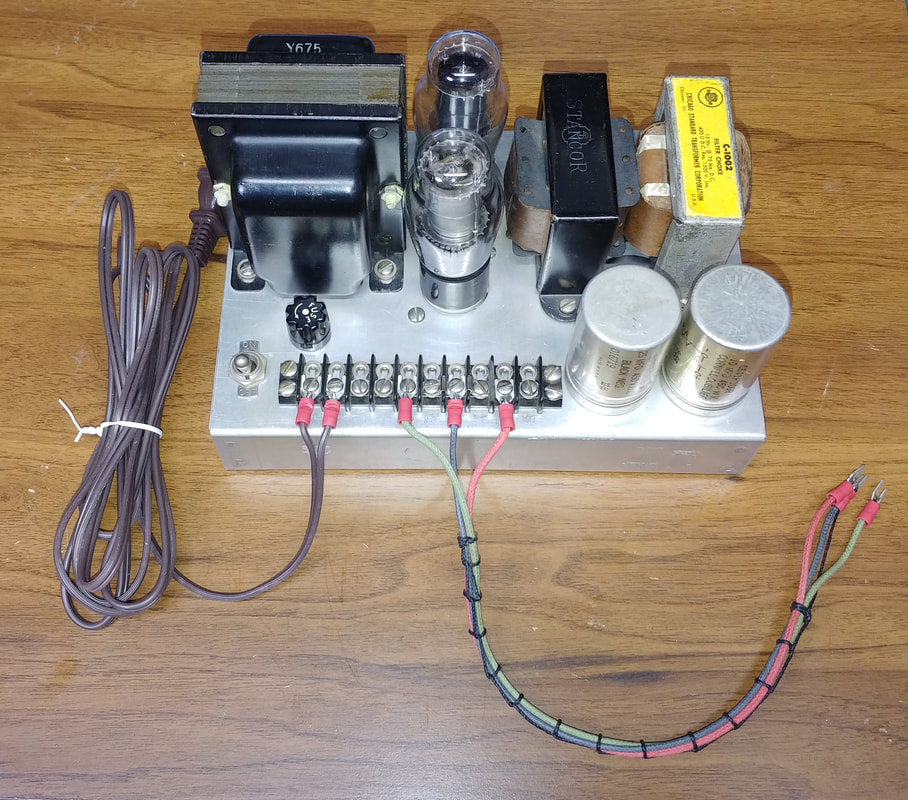
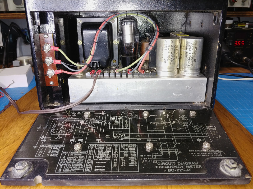
This unit has a homemade power supply in the battery compartment. It's nicely done, but looks like it was really designed for another piece of gear and was repurposed for the 221, because it has regulated 105V and 150V outputs plus an unregulated 265V output. There is also a 6.3VAC filament output but it is running about one volt too high, I guess from not having enough filament load. I need to fix that so it doesn't shorten the life of the tubes.
I've added a new power cord but I'm going to remove it from the terminal strip and run it through a grommet hole I'll add in the rear of the supply, because the AC is right next to the On/Off switch and sooner or later I'm going to reach in the back and stick my fingers on the AC if I don't move it. I also laced up a 3-wire cable for the output connections and I think I will remove the 105V regulator tube as it serves no purpose in this application. |
|
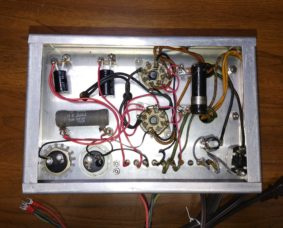
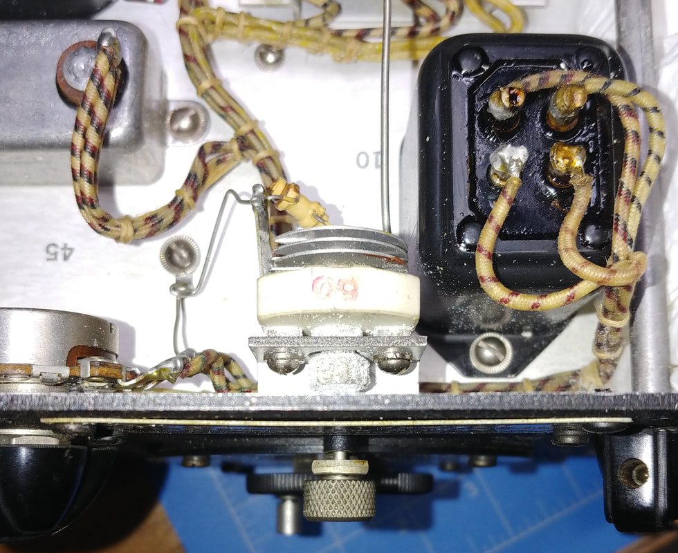
A look at the underside of the power supply chassis. The workmanship is good, but I did need to clean up a few connections. I installed two small terminal strips for new electrolytic capacitors and moved the connections over from the old capacitors. I also replaced the two high voltage rectifier diodes with 1N4007 diodes. The original diodes were 1N568, on which I couldn't find any data. Since I couldn't verify the specs, I thought it safer to just replace them. While I was in there I checked the filament current draw and added a 1Ω resistor in series with the output to drop the filament voltage to 6.3 - 6.4VAC.
|
|
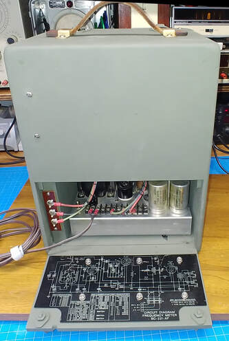
The power supply is a good fit in the cabinet. I connected B+ to the regulated 150V. Someone had originally connected it to the unregulated 265V, but B+ from the batteries is only 135V, so that was almost double the battery voltage. There is also a nice schematic reverse printed on an aluminum plate mounted to the drop-down door.
|
|
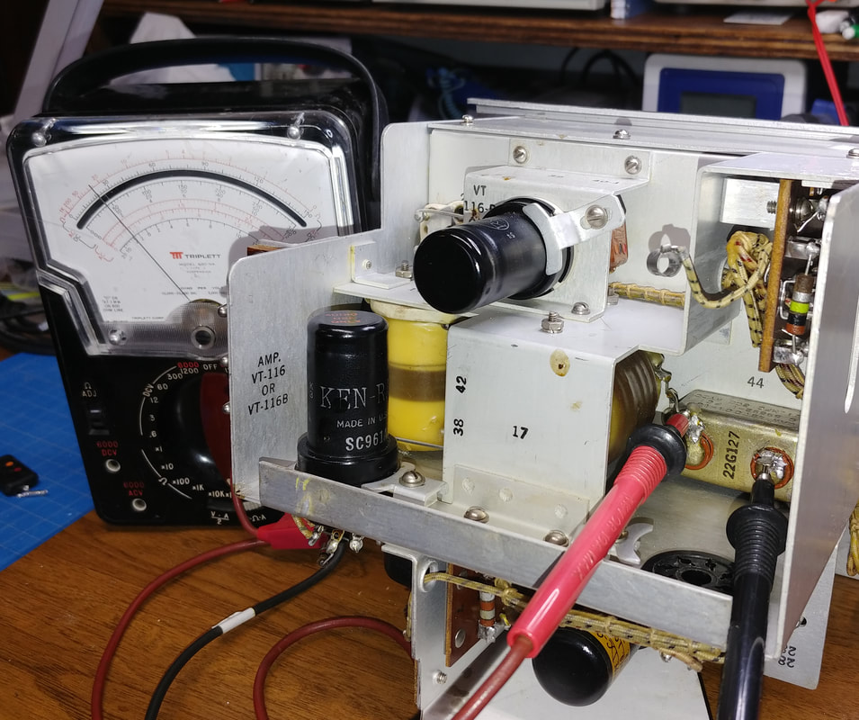
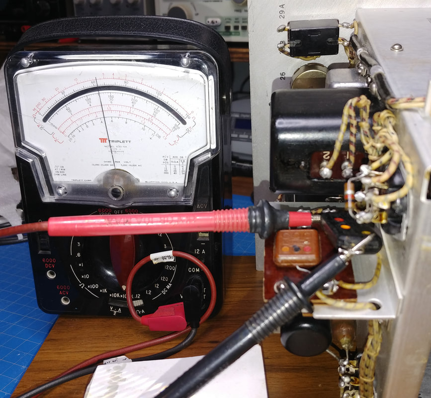
Here I'm using my Triplett VOM on the X100,000 ohms range to quickly check for EXCESSIVE leakage of the 0.1uf 600V capacitor labeled as #44 in the parts list (I've already disconnected one lead from the circuit). If it is excessively leaky I don't have to bother testing it on the capacitor tester, it's bad. And this one is definitely bad, so most likely it's paper and foil inside.
|
|
Doing a quick check on the 0.02uf Micamold capacitor shown as #9 on the parts list. It's marked as Type 342 and must be another paper and foil cap, so note to self that Type 342 Micamolds are not mica. I went ahead and tested it on the cap tester and it shows as shorted with 3V applied. Now that's bad.
Maybe this is a good spot for a couple of caveats on checking for leaky capacitors with an ohmmeter. First, an ohmmeter IS NOT a substitute for a capacitor checker. Second, all you can do with an ohmmeter is a resistance check for EXCESSIVE LEAKAGE and SHORTS. If a capacitor shows little or no leakage on an ohmmeter that DOES NOT mean it's good. It still needs checked on a tester that can apply up to the full rated voltage of the capacitor, or a tester like Mr. Carlson's. I've had 600-volt caps show virtually no leakage at all on an ohmmeter and fail miserably on my Heathkit IT-28 with as little as 3 to 10 volts applied. That's why I have an IT-28. |
|
I was expecting the .7uf 200VDC capacitor, #45 on the parts list, to also be paper and foil, but It must be some sort of film cap because it displayed zero leakage on the ohmmeter AND checked good to its full 200-volt rating on the IT-28. So it stays.
In circuit this 200V capacitor is directly across the B+, which, as pointed out earlier, was connected to the unregulated 265VDC from the power supply. But it seems to have handled the overvoltage OK. Even so, someone should have been paying closer attention. |
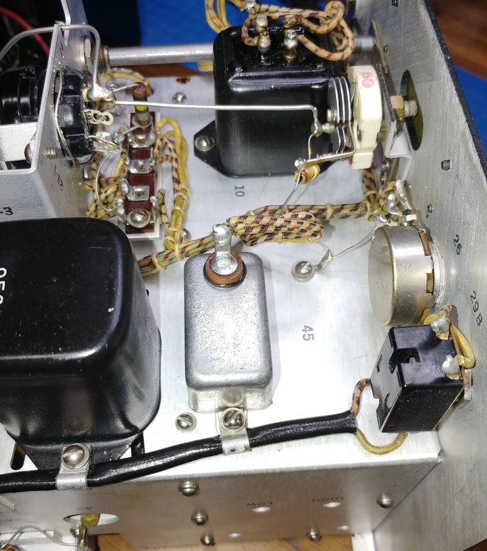
All three tubes checked good and I also checked the resistors, and while some were slightly higher than 10%, none were wildly out of range, so I let them be and the meter is working fine.
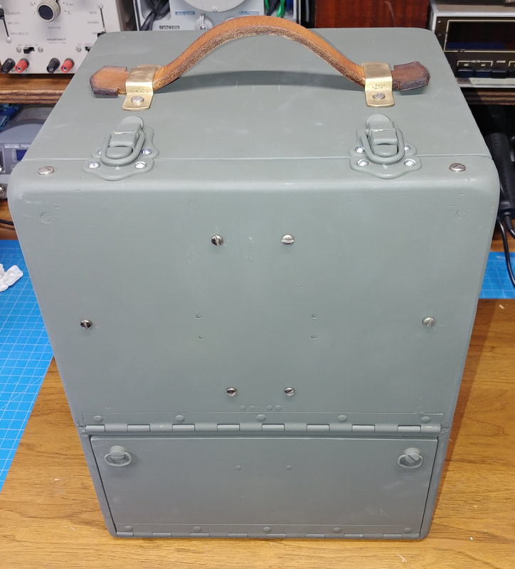
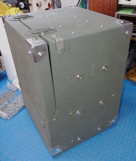
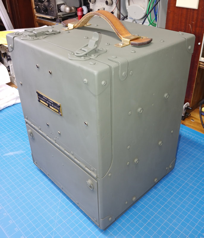
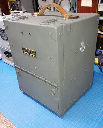
I've cleaned, sanded and repainted the case in a flat olive drab color. The paint is Rustoleum's Deep Forest Green Ultra Flat Camouflage paint. The cabinet is still missing some hardware, which is on order, so it's not quite done yet. And I still need to make the duplicate nomenclature tag for the front.
I've installed the power supply back in the bottom compartment for testing and to put it somewhere safe.
I've installed the power supply back in the bottom compartment for testing and to put it somewhere safe.
The meter is also back in the cabinet for a test. It's done except for checking and adjusting the crystal's accuracy, but that can still be adjusted with it in the case. I want to keep it all together while I wait on the parts order. It's looking so much better than when I started.
|
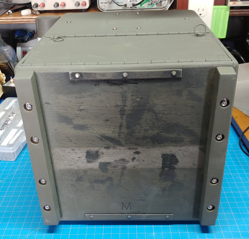
Someone removed the original wooden feet from the case, so I made new ones from a piece of 3/4" maple. Maple is hard enough that it should stand up well to the abuse the feet get.
What's left of the green paint on the bottom is original and I think the new paint matches fairly well. The gray stripe is where a metal band originally wrapped around the cabinet. |
|
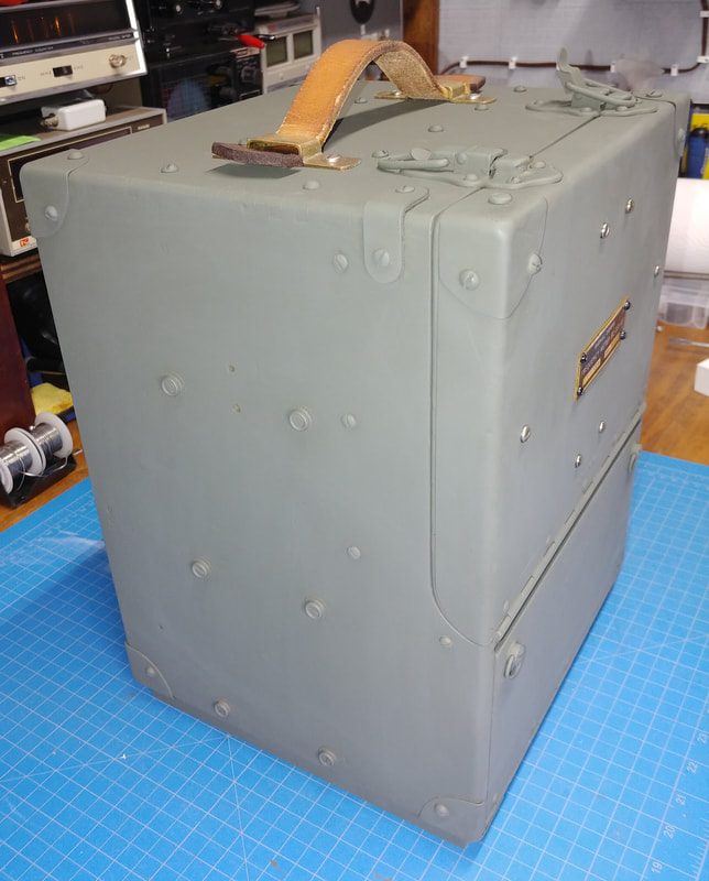
I don't understand why someone stripped the hardware from the exterior, but I've replaced most of it. I reinstalled new metal corners, but had to cut six of the eight to fit. I also reinstalled all the snaps and missing screws, but the metal band around the case won't get replaced because I don't have the original metal handle to screw the ends down. And the leather handle brackets are too wide to allow reinstalling the metal bars that held down the canvas covers on either side of it. Also, I'm still trying to find a set of matching D-rings for the sides.
I've temporarily removed the power supply, meter chassis, handle, book and schematic plate before giving the case a final coat of paint. |
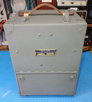
All dressed up and no where to go. I'm finished painting now, and everything has been reinstalled in the cabinet. The only hardware left to install are the two D-rings, whenever I can find them. Personally I think this looks 10X better than the shiny black paint with runs in it.
Page created 10/23/2020
Last update 12/5/2020
Last update 12/5/2020

