
Refurbishing A Panasonic RF-5000A
I picked up this Panasonic 11-band receiver at an auction. It's in very nice condition and has no nasty bangs, dents or other damage, just a little ding or two, which is to be expected for a 50-year old radio. The biggest issue is most of the band selector buttons are stuck. But I think this is a common issue with this model.q
|
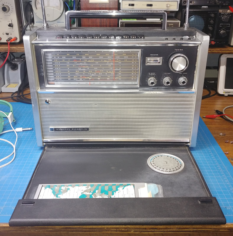
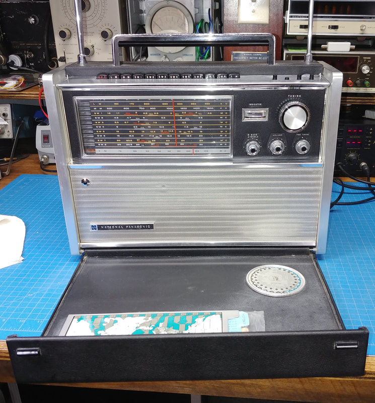
Looking at the front, the leatherette covering and the chrome trim are both in good condition. A few edges on the leatherette need reglued. The dial scales look great too, as do the time dial and maps. And all the papers are there. All three antennas are there too, but one whip has been pulled apart and someone tried to fix it and just made things worse, so I'll have to see what I can do to repair it. But overall it's a nice example of an RF-5000.
This radio is heavy for a portable at almost 21lbs, but is well built. Its 11 bands cover 150 to 400KHz Longwave, the AM Broadcast Band, Shortwave from 1.6 to 30MHz, plus FM from 76 to 108MHz. It has a tuning meter, a Fine Tuning control for SW, a BFO, a manual RF Gain control for use with the BFO and SSB reception, AFC for FM, ANL, and a mechanical filter for selectable bandwidths. Plus there are Bass and Treble controls next to the Volume, and the main Tuning dial has a weighted flywheel. The "A" model also has the add in RF-9451 AC power supply. |
|
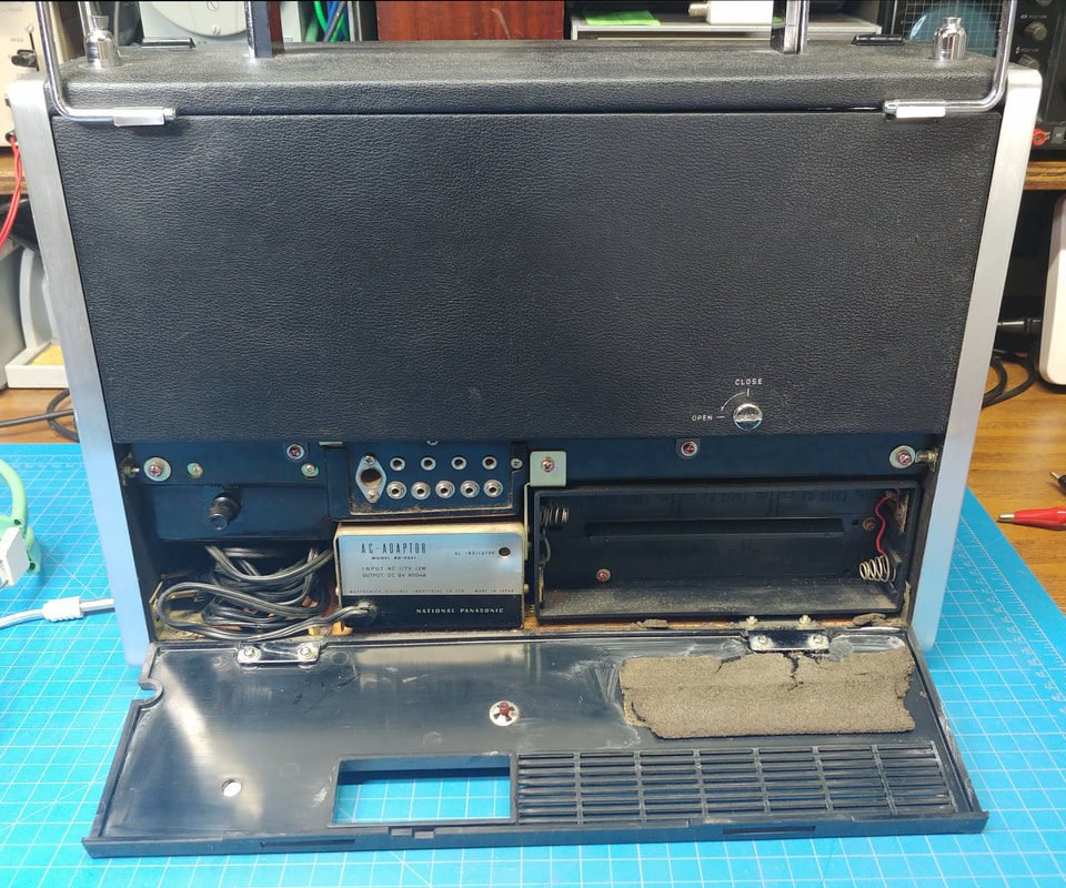
The rear is also in good shape and the only issue I see is the old foam on the rear door crumbling from age, but it will get replaced. At first I thought two contacts in the battery compartment had been damaged by old batteries, but the crud on them flaked right off and the terminals were undamaged.
|
|
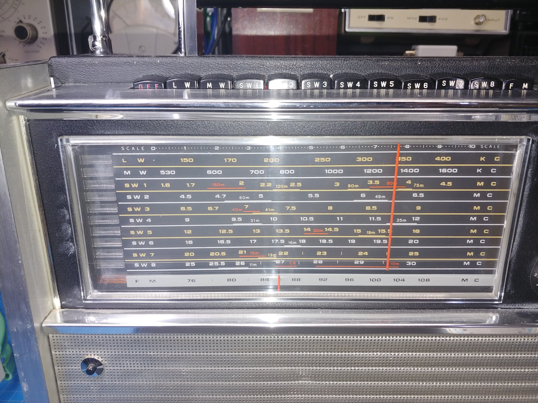
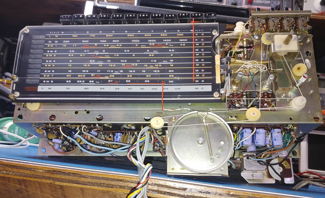
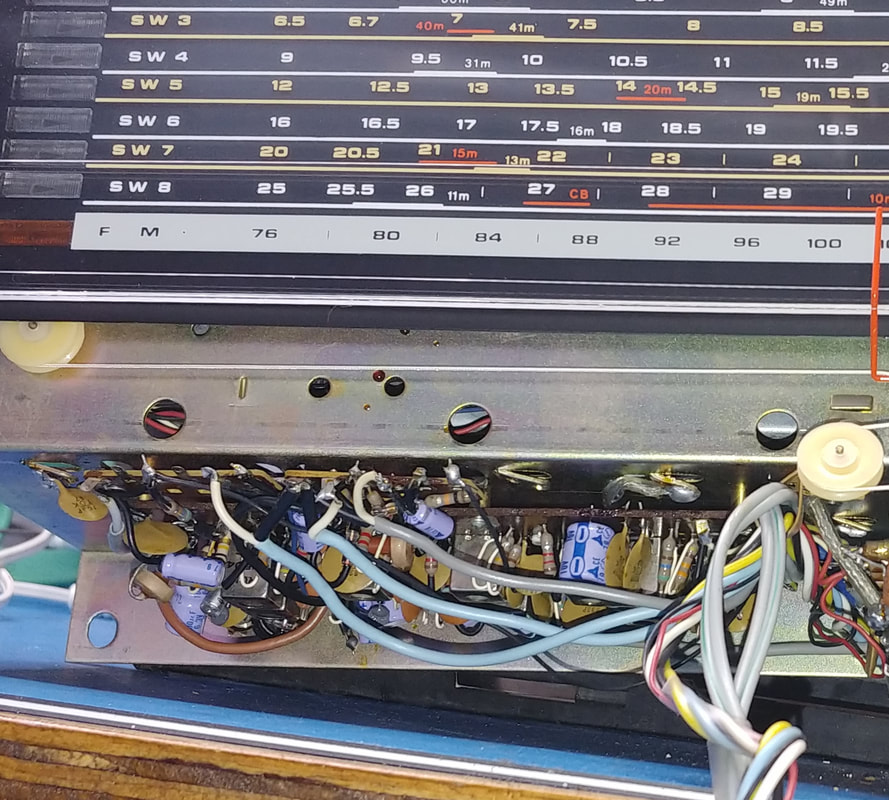
A closeup of the dial scales. The dial is actually made up of two dial scale plates sandwiched together. There are dial lamps to indicate the appropriate band depending on which band button is depressed, and there are lamps to light the scales.
|
|
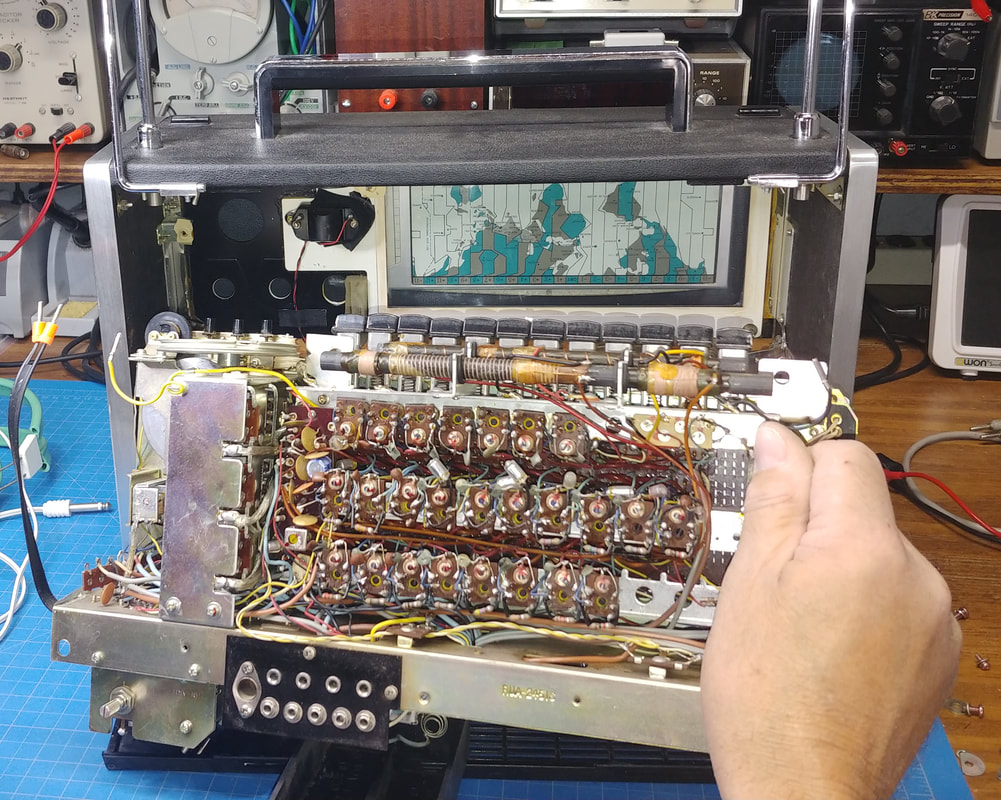
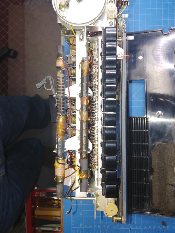
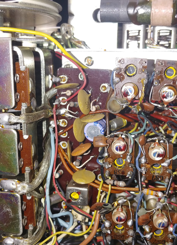
That's a lot of coils. Sure hope I don't need to adjust all those. To get the chassis out of the cabinet, all the screws painted red have to be removed and the wires to the antennas have to be unpluugged, along with the 300 ohm line. The black insert in the bottom has to come out before the chassis, but to get it out the power supply module has to be removed. And the front panel knobs have to come off. Then the chassis is tipped forward at the top as the back is slipped out of the chassis, to get the pushbuttons to drop down enough to slide out. Not sure how else to describe it, and putting it back in is just the reverse. But overall, it's surprisingly easier to remove the chassis than it would appear at first glance.
|
|
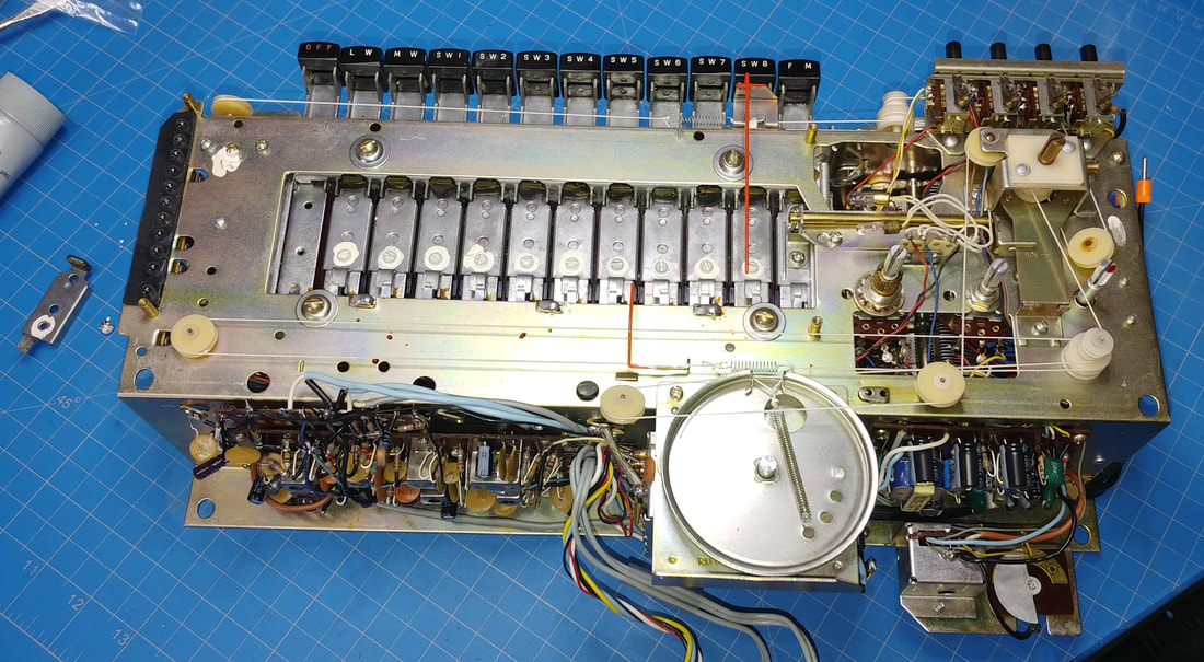
A look at the front of the chassis. Lots of pictures are useful to help get it back together if I forget something, and at my age I'm absolutely sure I'm going to forget a lot.
I think I'm going to need to remove the dial plates to get to the band switches to clean them and maybe replace the rubber on the switch stops. |
|
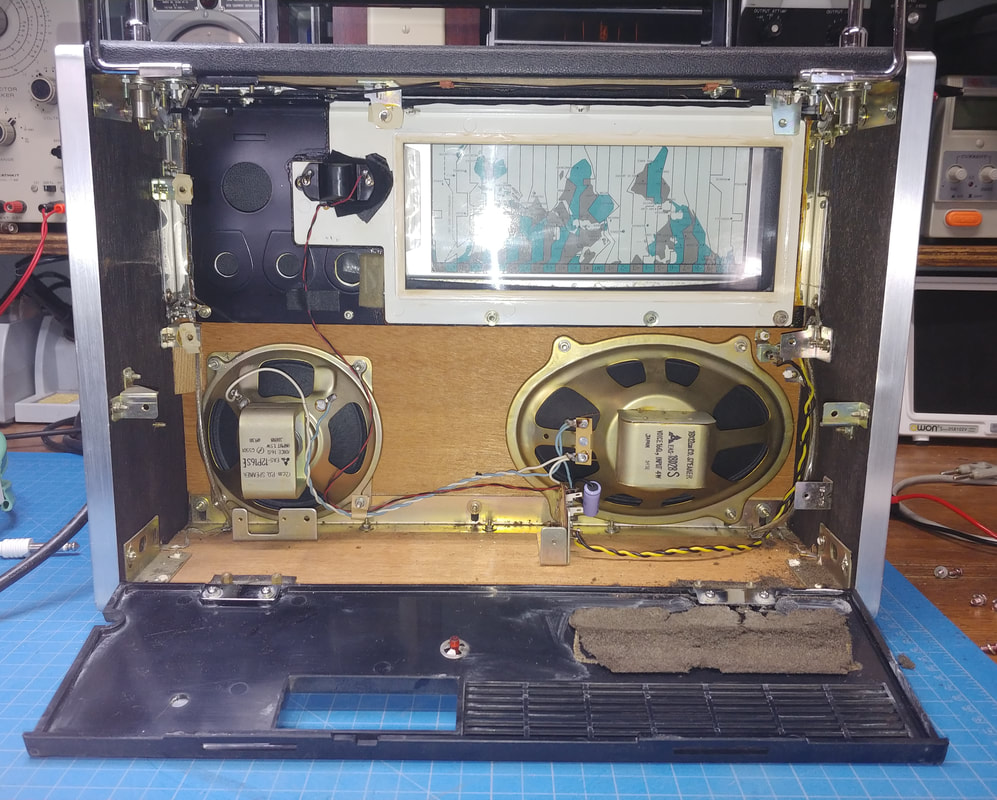
There's still several items in the cabinet after removing the chassis, including two whip antennas and the fold-down loop, the 5" round and 5x7" oval speakers, and the tuning meter. I see a few very small spots of rust in a couple places on the metal frame in the bottom. I think it's from where bits of the crumbling old foam were laying on it, probably for years.
|
|
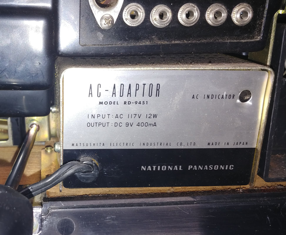
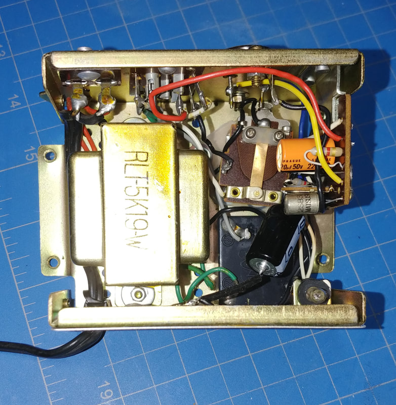
The AC adapter looks like an add-in module. Probably a couple of electrolytic caps in there in need of replacing.
|
|
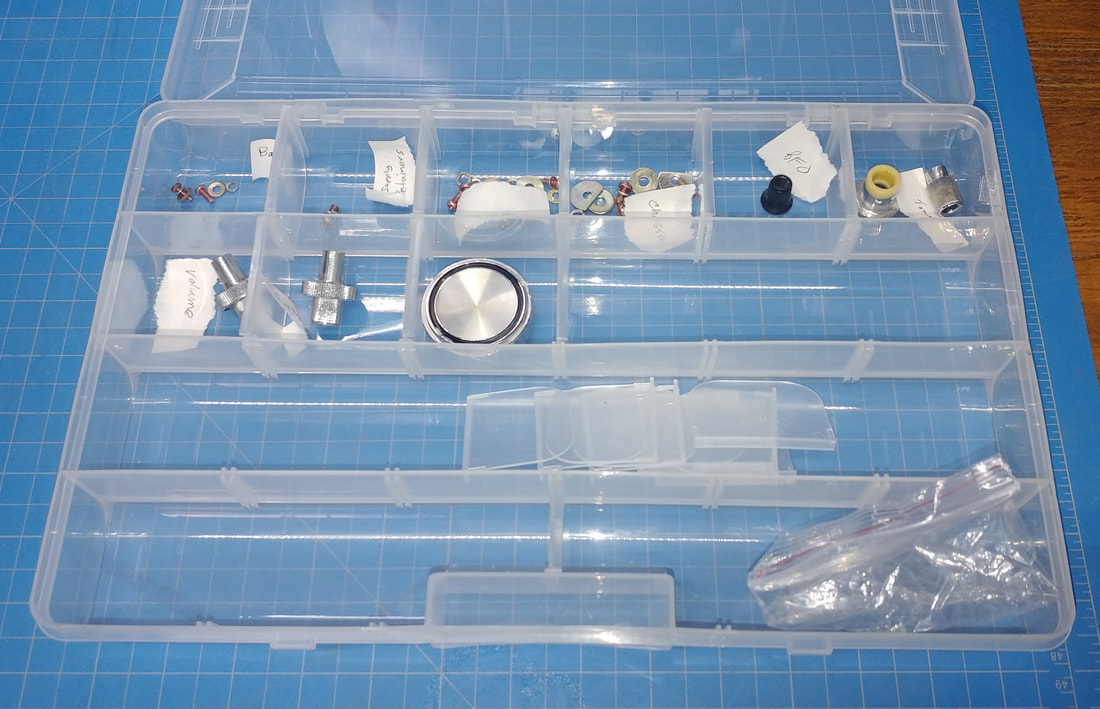
To help me remember what goes where, I'm sorting and labeling the screws and parts as I remove them. It should work out to be last in, first out if I do it right.
|
|
Getting to the band switches to clean them looks like it's going to be one of the hard parts of restoring this radio. They're sandwiched in pretty tight. I did spray some non-residue contact cleaner around the plungers, letting it run down into the switches, and it freed them up so they are moving now. At least that's good news.
|
|
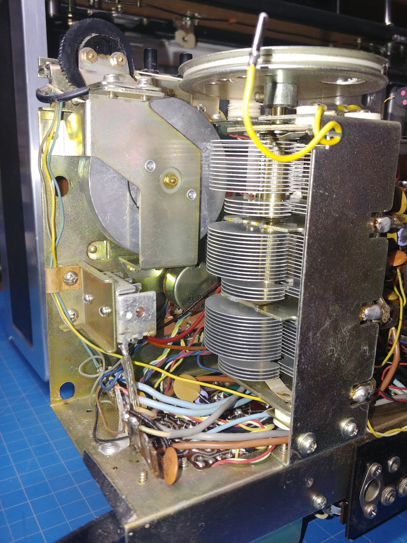
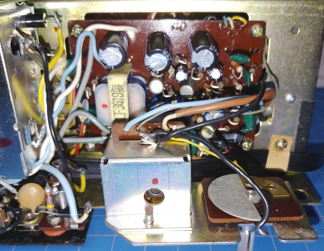
This is a look at the rear left side of the chassis showing the main tuning capacitor and the weighted flywheel which makes the tuning very smooth.
|
|
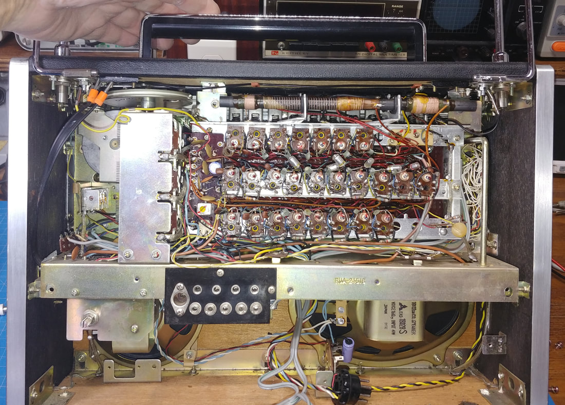
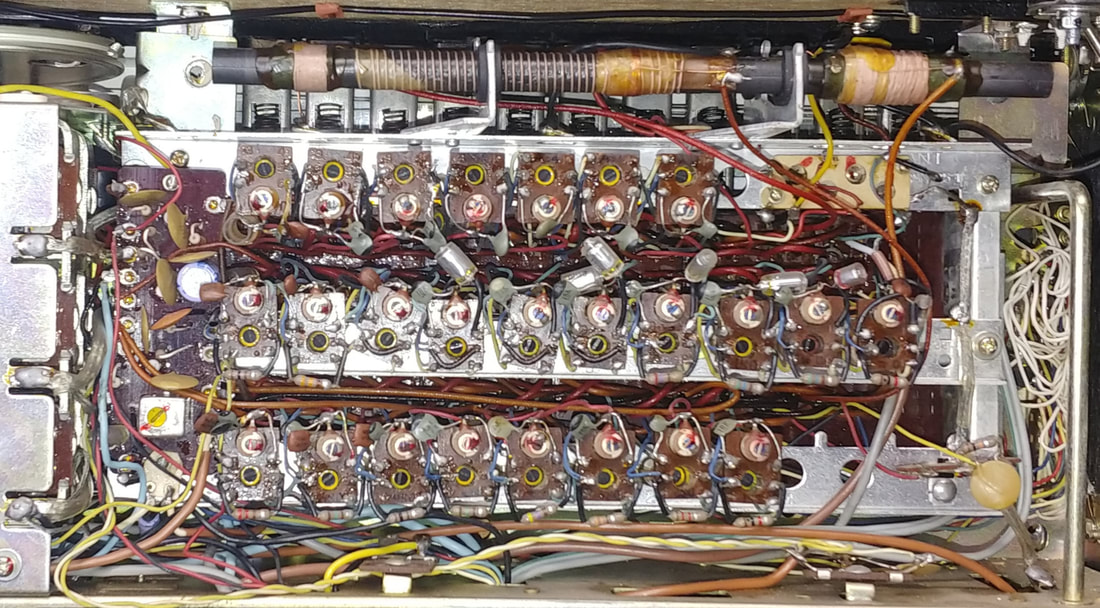
This is a rear view of the chassis just to get an idea of how much point-to-point wiring there is in this radio. This would have all been done by hand. They just don't make them like this anymore.
|
|
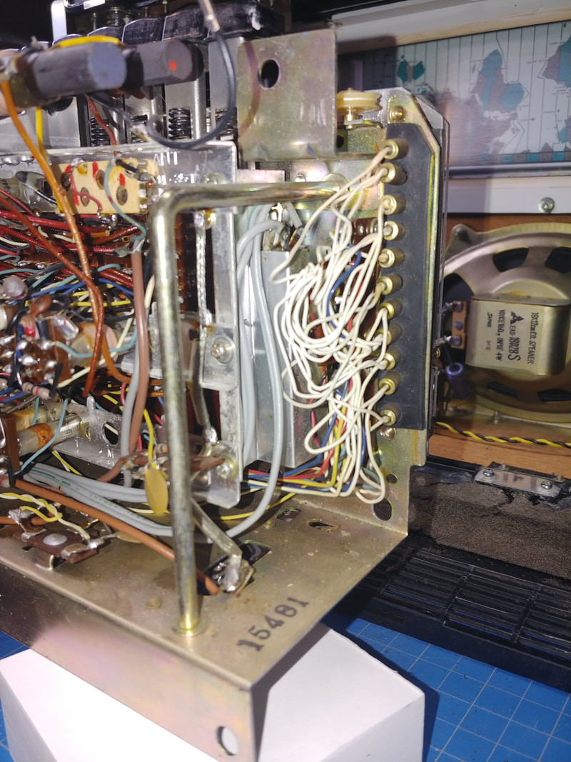
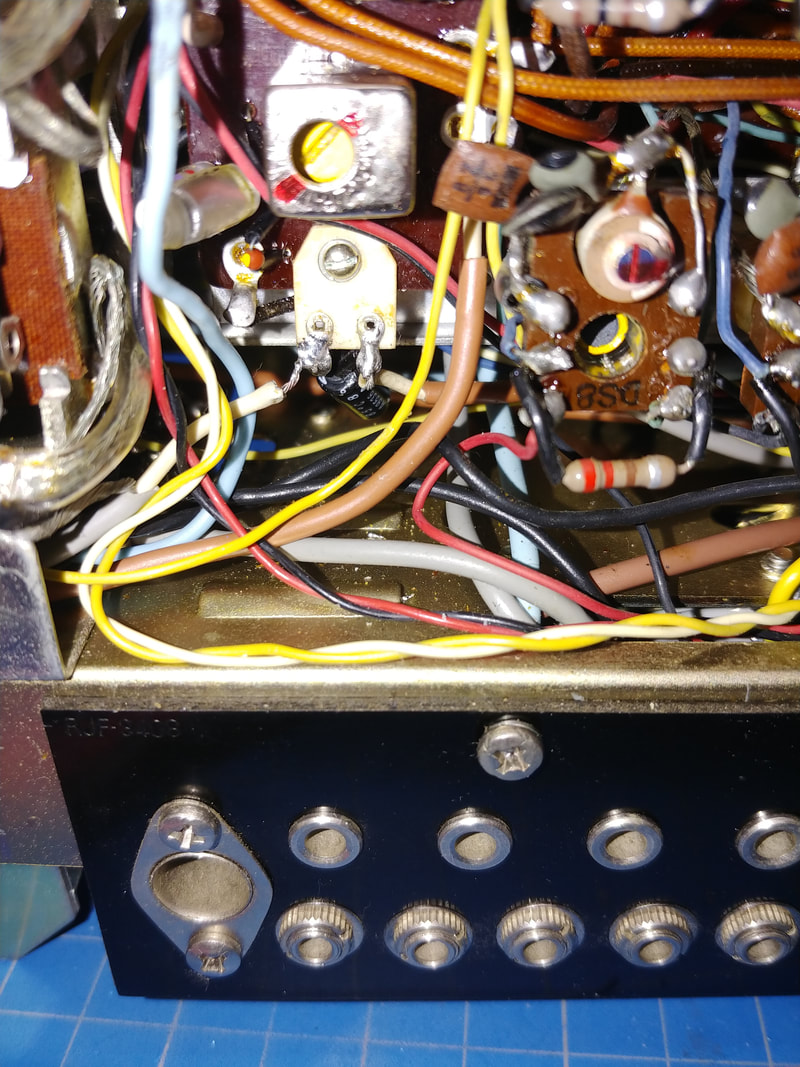
And this is the rear right view showing the dial lamps. The right angle bar is a hand hold to help when removing or inserting the chassis in the cabinet. I assume that's the serial number stamped on the corner.
|
|

|
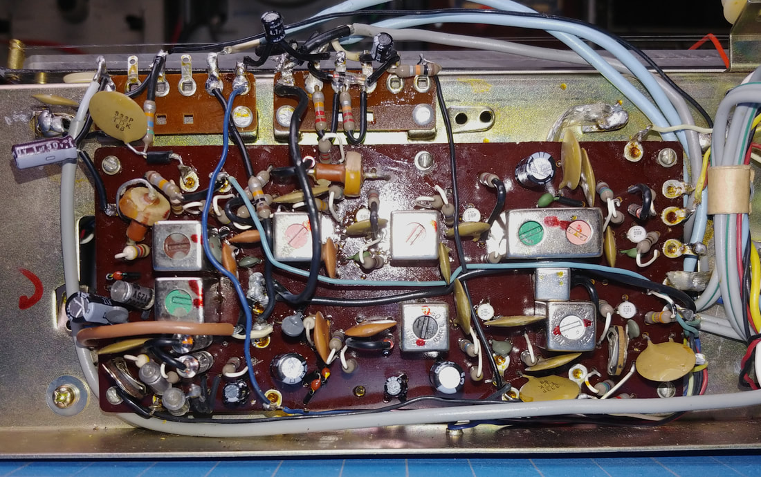
Most of the transistor circuitry is underneath the chassis. The first photo shows the IF board and in the second is the audio PCB. There's 26 electrolytic capacitors on all the PC boards and hidden here and there, plus 2 more in the power supply, and since they are at least 50 years old, all of them will be replaced. Some are going to be a bear to get out, but just because they're hard to get to doesn't magically make them good.
|
|
|
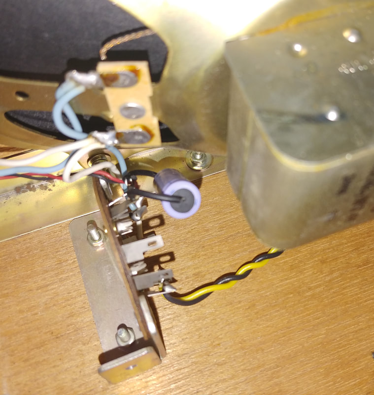
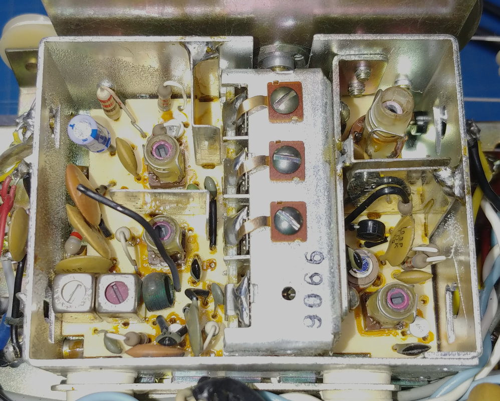
Not all the electrolytics are on the two PCBs under the chassis. There's one cap down by the speaker, and in the second photo there is the AM RF PC board buried in wiring next to the coils, with one electrolytic on it. It's going to be one of the hard ones to replace. Also, while digging this cap out, I found another hiding down below it, that is soldered to the little white two-terminal strip in the third photo.
|
The FM tuner has one electrolytic in it, and it definitely wins the prize for hardest to get out, but it will get replaced.
|
|
Two electrolytics caps were replaced in the power supply. Also, the output voltage was low (about 8.5V) and was readjusted to 9V using the on-board VR.
|
|
After replacing all the electrolytic capacitors on the audio board, I checked the originals on my capacitor tester and none of them are still good at their rated voltage. More than few are basically just shorts-in-a-can and don't make it past three volts, the lowest setting on the tester. The ones that got by at three volts failed at six volts. And there was dried electrolyte under a couple. So all of them definitely needed to be replaced.
|
|
All the electrolytics on the IF board have been replaced, too. I order capacitors only from reputable dealers, usually Mouser, so I can be sure I'm getting genuine caps and not fakes. Mostly I use Rubycon and Nichicon now days.
|
|
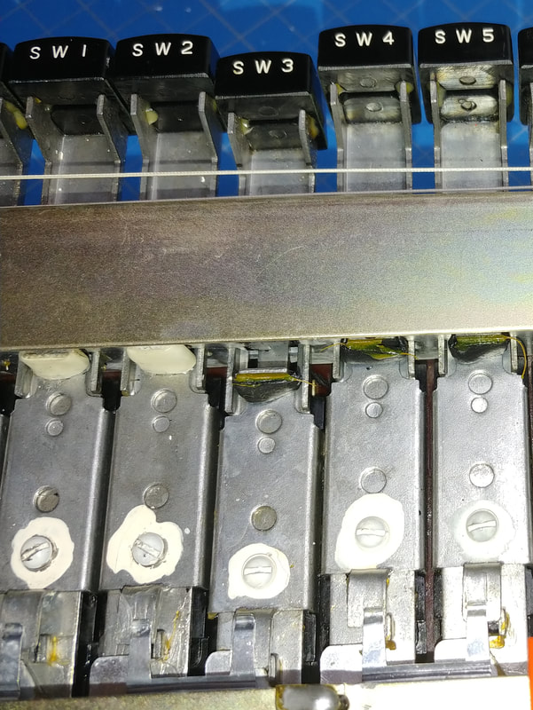
I've removed the dial plates to get access to the band switches. This was actually not too difficult, so kudos to Panasonic for giving some thought to serviceability. There is a rubber bumper on each switch stop and most are "squished" from age and use. It looks like they melted to the frame which was why the switches were stuck at first. As I replace them I'm also cleaning and lubricating the switches.
|
|
I've started replacing the rubber on the switch stops using a fiberglass reinforced rubber spaghetti tubing with a layer of clear heatshrink tubing over it. That gives me the correct height for the buttons and they should all be the same height when done. One way to tell that the rubber needed replaced was many of the buttons were at varying heights across the row.
To take off the switch stop just push the button until it latches and then remove the white painted screw. Just have to be careful of the spring tab at the bottom as it comes off and goes on. |
|
After finishing the switches I powered the radio on to see if it was working. FM sounded really good, but none of the other bands had anything but static. One thing all the bands except FM have in common is the AM RF board, so I gave it a good closeup inspection and discovered I'd accidentally broken a terminal connection to the mixer. I was trying not to unsolder any more wires than I absolutely had to when replacing the electrolytic on the board, but obviously I didn't desolder quite enough wiring. After repairing it I had good output on the LW, MW, SW1 and SW2 bands. But SW3 through SW8 were still dead.
|
While studying the switch wiring diagrams I spotted the likely problem; bands 3 - 8 all have a common connection to the mixer through a 1500pF capacitor that connects at the same terminal I had just repaired. And after a little more digging through the wiring I found the lead to the 1500pF capacitor had broken off from the PCB terminal. Resoldering it brought bands 3 - 8 alive. The wiring diagrams really saved me a lot of headaches troubleshooting what turned out to be a self-inflicted problem.
Troubleshooting the radio with the two pages of hard-to-read switch wiring diagrams in the free PDF manual is not easy. There's a lot of wires and connections and the diagrams are very dense, plus the original diagrams were two-color (black and blue lines) and when copied in B&W the lines blend together. So I ordered a manual from one of the online manual websites that offered color scans of those two pages of wiring diagrams. These color scans make tracing the switch wiring much easier. Unfortunately most of the rest of the pages in this $16.99 PDF manual are even worse than the free PDFs online. It's overall the worst manual I've ever spent money on, but the two color pages are a real help with understanding the switch wiring, so it wasn't a total loss.
|
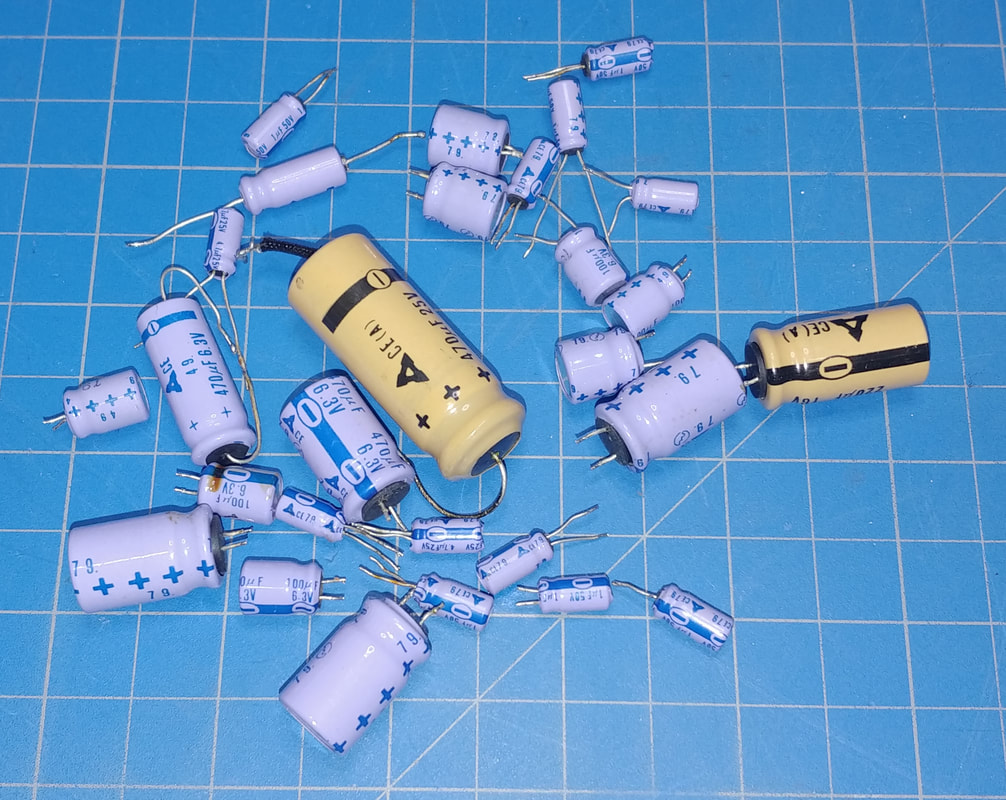
All the components replaced in the radio except one whip antenna. There's 28 electrolytic capacitors in the photo, which is every electrolytic in the set. The whip antenna was replaced because it was damaged beyond any simple repair.
Of course I also replaced the old rubber on the switch stops, but that crud went straight into the trash can as it was scraped off. |
|
The radio is performing very well and I've checked all the functionality to be sure everything is working. The bands are reading accurately, all the dial lamps are good, the tuning meter works, the functions of all four top buttons and the manual gain control are fine. All that's left to do, if I want, is maybe try to touch up the IF and RF alignment, but it appears to be pretty much spot on as it is, so I think I'll just leave it alone.
It's a sensitive radio with good, clear audio. I think getting all those old electrolytics out of it was the best thing I could do for it. It picks up stations inside my metal garage with its built-in antennas while my run-of-the-mill sets are just spitting out static. I used my TinySA spectrum analyzer, with it's whip antenna, to scan from below the LW band all the way up to the FM band from both inside and outside the building, and it shows my metal building makes a very good 20db or better attenuator. This makes the sets impressive reception using just its built-in antennas even more surprising. I think the RF-5000A is my favorite out of all the portables I have, and I'm really enjoying it. If I had to pick a downside it would be the 21lbs it weighs. But at least it's 21lbs of quality. |
Page created 11/21/2020
Last Edited 12/4/2020
Last Edited 12/4/2020
